Best Practices & Concepts for Computer Room Cooling
←
→
Page content transcription
If your browser does not render page correctly, please read the page content below
E N C L O SCEODM PMUOTUE N
                                                                                                R TRI O
                                                                                                      NOG M SCYOS OT LE IMNSG
                                                                                                                                 WHITE PAPER

                                                                              Best Practices &
                                                                         Concepts for Computer
                                                                                 Room Cooling

    800-834-4969
techsupport@chatsworth.com
    www.chatsworth.com
                                    ©2004 Chatsworth Products, Inc. All rights reserved. CPI and MegaFrame are registered trademarks of Chatsworth Products, Inc.
                             All products quoted are subject to availability based on manufacturing capacity and shipping dates should be considered estimates only.
                              While every effort has been made to ensure the accuracy of all information, CPI does not accept liability for any errors or omissions and
                             reserves the right to change information and descriptions of listed services and products. All other trademarks belong to their respective
                                                                                                                               companies. MKT-60020-233 Rev.2 06/08
Computer equipment cooling air delivered from a raised floor air source can be optimized by applying some basic thermal man-
agement concepts, which sometimes contradict conventional wisdom or intuition. This optimization can either produce increased
cooling or reduced cooling costs, and often both apparently mutually exclusive objectives can be met simultaneously. This paper
will review the effects of heat on computer equipment and some of the benefits of improving cooling, before offering some insights
on how to actually deliver that improved cooling, based on some simple principles of conduction and forced convection heat
transfer and an understanding of fluid dynamics both under the raised floor and within an equipment enclosure.
Heat is the enemy of electronic equipment. According to BCC, Inc. “Report GB-185R,” over half of electronic failures are caused
by temperature, and, since those heat sources are transistor densities and speed, which are continuing to increase, the logical
conclusion, everything else being equal, is that those failure rates will continue to climb. As a matter of fact, according to the
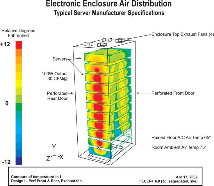
Industry Cooling Consortium, consisting of IBM, HP, Dell, Nortel, Cisco among others, we are right now in the middle of the steep-
est growth slope in heat densities (watts per square foot) for most computing and communication electronic equipment, as report-
ed in a white paper by the Uptime Institute.
Best Practices & Concepts for Computer Room Cooling
1The flattening out of these curves around the years 2005-2007 should not be interpreted as reason to believe we only need to cool
heat loads that will not quite be doubling over the foreseeable future. This forecast was based on the Consortium’s original
assumption that Moore’s Law, a primary heat driver wherein transistor counts per chip double every eighteen to twenty four
months, would finally start to reach its physical boundaries. Subsequent to the release of this report, Gordon Moore has forecast-
ed at least another decade of this density growth trend, so we can now plan on dealing with communication equipment heat loads
that will double by the year 2005 to a sizzling 6000+ watts per square foot and server and storage equipment heat loads increas-
ing to 2000 watts per square foot in another three years and then increase another 1000 watts in another six years, conservative-
ly assuming a continuing linear relationship between transistor-count growth and temperature increases.
The grapevine noise is that some chipmakers already are capable of producing significantly faster and more powerful micro-
processors, but are not able to deploy them in real applications in the market because of the lack of solutions for the extra heat.
Therefore, everyone who contributes to cooling those microprocessors, whether at the chip level, board level, shell level or
rack/cabinet level, becomes a technology-enabler for new generations of computing power.
Temperature affects IT hardware in a variety of ways and often seemingly inconsequential changes can have significant perform-
ance and economic impacts. Arrhenius reactions result in shortened capacitor life and semiconductor degradation at elevated
temperatures. A good rule of thumb is that every 10°C increase in ambient temperatures produces a 50% reduction in long-term
reliability of IT hardware. In fact, both military standards and Telcordia standards have correlated CPU operating life to tempera-
ture. It is interesting to note that most CPU operating temperature ranges have upper limits around 95°C, but the MIL-HNBK-217
and Bellcore data suggest that running continuously at that temperature level will limit CPU life to a year or less, while a 5°C reduc-
tion can actually triple the life expectancy of that equipment.
Best Practices & Concepts for Computer Room Cooling
2Temperature also effects clock speed. For a 1500 MHz CPU, every 10°C temperature reduction results in a 2% increase in clock
speed. While 2% may not seem particularly significant, in a larger data center dedicated to processing large numbers of transac-
tions with 2 RMU servers, losing that extra 2% of transaction turnover means having to buy and install an otherwise unnecessary
server every two and-a-half racks.
Best Practices & Concepts for Computer Room Cooling
3With an understanding of the impact of high temperatures on CPUs and the promise of performance and economic benefits to be
derived from applying more cooling to IT hardware, our informed and exuberant computer room manager needs to guard against
the temptation to invest in more computer room air conditioning units (CRAC) or to merely crank down the thermostat. In some
instances, these actions will merely be wasteful; in others, the colder air may actually result in creating a more serious heat prob-
lem. The first recommended course of action is to manage the air movement under the floor tiles and then to manage how the
cooled air is actually delivered to the equipment. When this is done well, we have seen CRACs removed from service and thermo-
stat temperatures raised while cooling has improved.
Proper air management depends on having at least a basic understanding of how the principles of forced air convection heat
transfer rates are responsible for equipment cooling. Most rack-mounted equipment is fan-cooled. Typically, these are 10-30 CFM
axial fans that draw the air in the front and exhaust it out the rear, though there are an isolated handful of product platforms that
move the air from side-to-side. Inside the equipment, conduction heat transfer takes place in the direct-contact molecular inter-
action between a microprocessor (or its socket) or other heat source and a heat sink. Then forced air convection heat transfer
takes place as the air that is drawn in the front of the equipment by the small axial fans passes across the heat sink. That function
is described in the following equation:
Q= hA(Tw-Tf)
Where q = the heat transfer rate
h = the convection heat transfer coefficient
A = the surface area
Tw= the temperature of the surface
Tf= the temperature of the fluid
While historical practice and conventional wisdom have typically focused on getting the heat out of the cabinet and fretting over
hot spots (usually somewhere around the upper rear of the cabinet), the principles of forced air convection heat transfer indicate
clearly that the real benefit to CPU performance and life results from the delivery of the coldest available air directly to the con-
ductive surface area attached to the microprocessor. In fact, in the dynamics of heat transfer, the temperature of the delivered air
(Tf) is the only variable over which the equipment installers and users have any control and is the objective of air movement man-
agement.
Managing air movement is quite simply just a matter of putting the air to work where it is needed and the first step in that process
is to reduce bypass air – air that is escaping from under the floor to places where it is not doing its cooling work. Triton
Technologies has mapped the under floor cooled air in over a hundred computer rooms and data centers and has found that in the
vast majority of sites 50-80% of the air delivered into the room is bypass air. Reducing bypass air has multiple benefits. First, seal-
ing off all the escape points for bypass air will raise the static pressure under the raised floor which will in turn increase the air
flow (CFM) at the points of need. The chart below correlates static pressure to CFM to cooling delivered.
Best Practices & Concepts for Computer Room Cooling
4Computer rooms with 50-80% bypass air will have static pressure under the raised floor of approximately 0.01” of water, which will
deliver around 200 cubic feet of air per minute through a 25% open perforated floor tile. That air delivery equates to around 700
watts of cooling, which, based on the heat load curve developed by the Industry Cooling Consortium previously discussed, is well
short of the cooling required for one fully loaded cabinet. Furthermore, since typical computer rooms will be laid out so two to four
cabinets will share the air from one perforated tile, the cooling is woefully inadequate that is delivered by that 200 CFM air flow.
By blocking off enough of the bypass air to raise the static pressure under the floor to 0.025” of water, the air flow through that
floor tile will increase from 200 CFM to 350 CFM thereby delivering, without any changes to the CRAC or air handler settings, near-
ly double the cooling at around 1.3 kW. That cooling may now be adequate for at least one cabinet full of equipment. However,
by sealing off enough bypass air to raise that static pressure to 0.1” of water, the air flow through that floor tile is increased to 700
CFM and the resultant cooling delivered is increased to 2.8 kW.
There are three primary sources of bypass air to contend with to realize the cooling benefits of optimized static pressure. Cooled
air can actually escape the room through open doors and through the access points into the room under the raised floor for cable,
power and plumbing. Keeping doors closed is a simple matter of common sense discipline. Under the floor, however, most FM200
fire suppression systems will require that points of entry are already sealed. Otherwise, those points of entry should be sealed
with any standard plenum-rated foam, fabric or other pliable material. A second source of bypass air is removed floor tiles. Again,
a little information-based discipline is usually adequate to keep floor tiles where they belong when access under the floor is not
immediately required. The largest source of bypass air is innocent, intentional mis-location of floor tile openings.
Floor tile openings may be any holes cut in the floor tiles, primarily for cable pass-through, or any of a wide variety of standard
grills and perforation patterns and these openings are typically deployed around computer rooms in counter-productive arrange-
ments. As noted in the static pressure discussion, the only cold air escape should be where cold air is required for forced air con-
vection to drive a higher heat transfer rate across the heat sources. Therefore, perforated tiles located around open work areas
for human comfort are effectively reducing under-floor static pressure, reducing cold air CFM at points of need, reducing heat
transfer rates, and thereby reducing CPU performance. Even worse, however, are floor tile openings located where the heat is. I
have seen a data center organized correctly into hot aisles and cold aisles and then a manager had complained about being too
hot while walking behind cabinets and had some perforated floor tiles installed in those aisles to “help move the hot air out.” Not
only is this action reducing the effective cooling delivered to the servers and other equipment mounted in the cabinets, it is cool-
ing the heated air before it returns to the CRAC to be chilled and re-circulated. CRAC efficiency is driven by the wide difference
between the source air temperature and return air temperature and the general rule of thumb is that every two degree reduction
in that difference results in a 10% reduction in CRAC efficiency, primarily due to energy required to maintain a stable relative
humidity. For example, a 2°F reduction in that temperature difference would lead one 20 ton CRAC to produce 2000 gallons of water
in a year to re-humidify source air after the cooled return air had been dehumidified. Leaving the cable access ports in floor tiles
in the rear of cabinets unsealed around the cable is the worst source of bypass air. Since there will be one opening per cabinet,
the sheer volume of escaped air will be greater than any other source. In addition, by delivering the coldest available air directly
to the warmest equipment exhaust air, the whole problem of reducing the temperature differential between source air and return
air is multiplied. Cable can be sealed around with plenum pillows, plenum foam or special panel cut-out inserts with brushes to
close around the cable.
Increasing static pressure alone does not guarantee an optimum flow of chilled air to the most critical points of need – air deliv-
ered under the raised floor is directional and must be managed properly. Triton Technology Systems, a marketer of raised floor air
management products and services, has accumulated an extensive body of empirical research indicating not only that air streams
from CRACs tend not to mix, but if the CRACs are located at right angles to each other they will cause their cooled air output pat-
terns to be diverted in angles that cannot be predicted by return air patterns in the computer room above the floor. At best, these
patterns will result in the wasted expense of inefficiently operating cooling equipment; at worst, they will create hot spots in a
computer room that will jeopardize the performance of computing equipment and the integrity of data.
Best Practices & Concepts for Computer Room Cooling
5The “Under-Floor Air Dynamics” graphic illustrates an example of the effects of these air movement patterns. The different col-
ored areas indicate likely paths for the under-floor air movement, while above the floor in the computer room, the return air to the
CRACs may more likely be exactly opposite the expected delivery path indicated by the arrows at each CRAC. Therefore, CRAC-2
may be getting return air from point B, mixed with some of the return air originally delivered by CRAC-3, whereas CRAC-4 may be
seeing return air from point A with some mixing with return air originally delivered by CRAC-3, or CRAC-1 could also be seeing
return air from Point A. Assuming something like a 15°F temperature rise on the cooled air as it passes through all the equipment
in a cabinet, confusion and even disaster can be predicted. CRAC-1 is seeing return air at 86°, driven by the hot spot at Point A
and continues to drop its temperature to deliver more cooling, which fails to be delivered to the hot spot. CRAC-4 is seeing 86°
return air from point A mixed with some 75° return air in the CRAC-3 path, which keeps it running cool. CRAC-2, on the other hand,
is seeing 70° return air from Point B passing through some 75° return air from the CRAC-3 path. If the chiller thermostat is set at
72°, it is conceivable that CRAC-2 may shut down its chiller and just blow unchilled air into the under-floor space. Unfortunately,
that ambient air will be delivered to the hottest spot in the room. Meanwhile, the astute site administrator will notice the hot spots
and drive down the temperatures further on either or both CRAC-1 and CRAC-4, which unfortunately will conspire to drive down
the return air temperature that much further to CRAC-2, thereby preventing any cooling from being delivered to the hottest spot in
the room. Once this train is boarded, it is darned difficult to get off.
A computer room with all the air and all the cable running in the same parallel direction, commonly referred to as a “hot aisle-cold
aisle” set-up, is the best way to make air direction both below and above the floor predictable, create some redundancy for pro-
tection against CRAC failures or service down-time, and remove cable obstruction as a source of turbulence, reduced static pres-
sure and lost CFM.
Ideal Data Center
Best Practices & Concepts for Computer Room Cooling
6Finally, with maximized static pressure under the floor for optimum CFM delivery of chilled air and an ideal organization of CRACs
and equipment cabinets in the data center, the site administrator must avoid the normal inclination to locate the hottest equipment
closest to the CRAC. Often the air velocity straight out of the CRAC may be too high to be diverted up through a perforated floor
tile located too close to the CRAC. In fact, by the physics of the Venturi Effect, the velocity of that chilled air racing by a nearby
perforated floor tile may very well be sufficient to draw ambient room air and/or heated return air into the under-floor space.
Therefore, not only will that proximity fail to deliver cooling to the hottest equipment, but it may also result in raising the tempera-
ture of the chilled air delivered into the entire room. The recommendation here is to avoid locating perforated tiles too close to the
CRAC and, where possible, locate passive, connectivity equipment closest to the CRAC, to maximize space utilization.
Effect of Under-Floor Air Velocity
Once the computer room is organized effectively, the same principles should be applied to the cabinet/enclosure itself. Attention
to static pressure and airflow management within the cabinet serve to realize the greatest benefits from the attention paid to
organizing the room itself for maximum cooling. These principles will be applied in different ways, depending on the total environ-
ment and the heat load. For example, if the bypass air elimination exercise produced adequate CFM through all the perforated floor
tiles, the cabinet should either have no doors or, if required for security, doors with a minimum 60% open mesh for maximum air-
flow and is best not equipped with top mounted fan kits. “Adequate CFM” will be defined by the heat load in cabinet or cabinets
served by a perforated floor tile versus the cooling delivered, which can be plotted on the “Relationship Between Under-Floor
Static Pressure and Cooling” line graph. For example, 700 CFM will deliver nearly 3kW of cooling, or 1.5kW per facing cabinet. Top
mounted fan kits can be counterproductive to the degree they allow some mixing of return air with the source air in the cold aisle
and any resultant temperature increase will produce a commensurate decrease in the heat transfer rate within the mounted
equipment. If cabling obstacles in the rear of the cabinet or other concerns will make it difficult for the small server fans (10-30
CFM) to push the hot air out of the cabinet, rear door-mounted fans that push that air directly into the hot aisle and keep the cab-
inet between the source air and the return air will keep the total system running more efficiently and effectively.
If, on the other hand, not enough static pressure improvements can be made to deliver the CFM through the perforated tile in the
center of a cold aisle to provide the cooling required by the heat load in the cabinet or cabinets, then a more focused approach
of pumping the air directly into the cabinet and distributing it with some kind of booster may be required. In this scenario, static
pressure is again important in the space in front of the rack-mounted equipment where the air in-takes are located. Static pres-
sure is increased by utilizing a solid panel front door (though peripheral venting is acceptable and sometimes desirable), filler pan-
els in unused RMU spaces between equipment, and some means of sealing between the equipment and the cabinet side panels.
For this reason, even where cabinets are bayed together, typically without side panels, it will be preferable for two cabinets to at
least share a side panel. In addition to maximizing the static pressure in that three cubic foot space of air in the front of the cabi-
net, this sealing will also discourage the exhaust return air in the rear of the cabinet from re-circulating and mixing with the cool
source air before it is drawn into the servers. Top mounted fans may be deployed in this configuration because their output will
not mix with the equipment input air. The “boost” is provided by mechanisms designed to focus the coldest available air directly
on the most critical point of use. Products are available which do this with centrifugal blowers which direct the chilled under-floor
air through a nozzle up the front of the equipment or with fans which direct the air into a “plenum” door with vents or baffles that
will direct the air into the cabinet to points of need.
Best Practices & Concepts for Computer Room Cooling
7The effectiveness of these focused approaches is shown in the comparison of the two Electronic Enclosure Air Distribution com-
putational fluid dynamics models. The “Typical Server Manufacturer Specifications” model shows expected cooling toward the
bottom of the cabinet and some counter-intuitive cooling at the top of the cabinet. The upper cooling results from the top mount-
ed fans drawing air in through the top of the high air flow mesh front door. Hot spots remain in the center of the cabinet as the top-
mounted fans fail to draw significant air by the front of the equipment, because the mesh doors provide less resistance than the
equipment in the cabinet. The focused air delivery, on the other hand, will deliver most of the difference between the under-floor
air temperature and the ambient temperature directly to the equipment air in-takes.
Best Practices & Concepts for Computer Room Cooling
8High-powered fans either blowing air into the bottom of a cabinet or pulling air through from the top of the cabinet are not consis-
tent with the principles discussed in this paper. For example, such fans will typically push or pull cooled air through both the front
and back of the cabinet, thereby cooling exhaust air (return air), reducing the temperature differential between source air and
return air and decreasing CRAC efficiency.
Data center equipment cooling does not need to be mysterious magic, but it often requires more than common sense, especially
since so much of the action happens out of view below the raised floor tiles. The key points to remember are to only spend your
cold air where it is really needed by your equipment, avoid mixing “used” return air with cooled source air, keep life simple and
predictable by running all your air and under-floor cable in one direction and parallel to each other, and the name of the game is
delivering effective cooling, not merely getting rid of hot air.
About the Author: Ian Seaton, Market Development for Chatsworth Products, Inc., is responsible for the CPI Delphi Enclosure
Blower product line. He can be reached at iseaton@chatsworth.com. For more information visit www.chatsworth.com or call
800.834.4969.
Best Practices & Concepts for Computer Room Cooling
9You can also read