Service Manual Top Load Washer Kraken 27" - June-2016 - Visualizador MABE
←
→
Page content transcription
If your browser does not render page correctly, please read the page content below
Service Manual

June-2016

Top Load Washer Kraken 27”

 Ingeniería de Servicio
                          -1-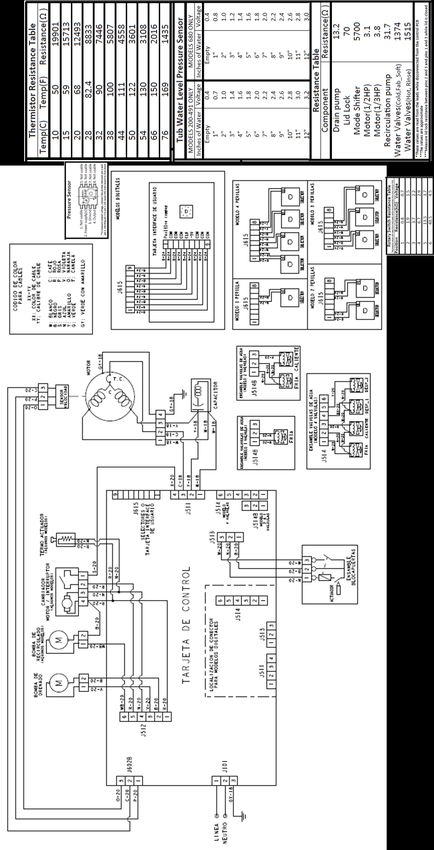
IMPORTANT SAFETY NOTICE

IMPORTANT SAFETY NOTICE

The information in this presentation is intended for use by individuals
possessing adequate backgrounds of electrical, electronic, & mechanical
experience. Any attempt to repair a major appliance may result in personal
injury & property damage. The manufacturer or seller cannot be
responsible for the interpretation of this information, nor can it assume any
liability in connection with its use.

WARNING

To avoid personal injury, disconnect power before servicing this
product. If electrical power is required for diagnosis or test purposes,
disconnect the power immediately after performing the necessary
checks.

RECONNECT ALL GROUNDING DEVICES

If grounding wires, screws, straps, clips, nuts or washers used to complete
a path to ground are removed for service, they must be returned to their
original position & properly fastened.

Ingeniería de Servicio
                                    -2-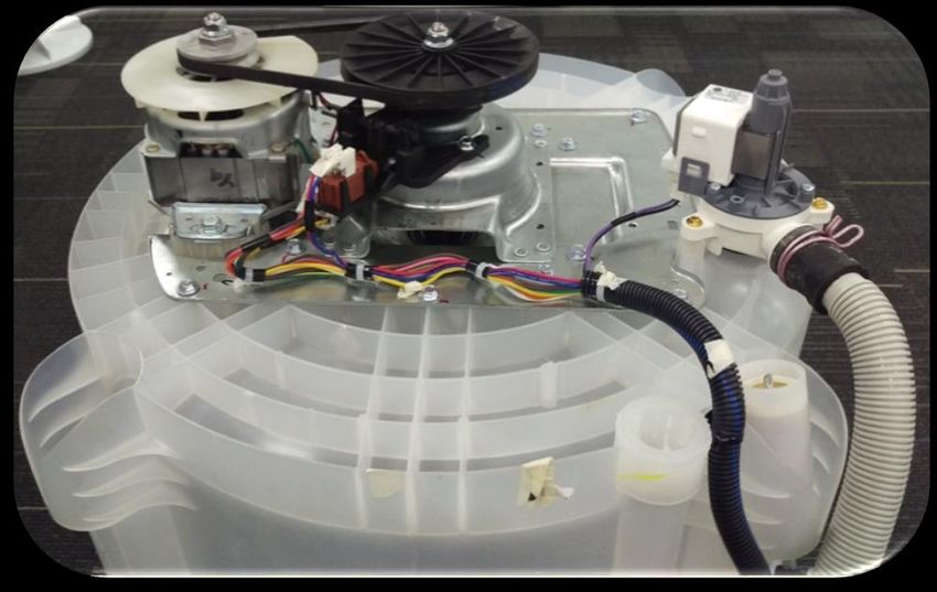
Mabe authorized Service Technicians are required to use the Personal
Protection Equipment (PPE) listed below, for your own protection.

Dyneema® Cut Resistant Glove          Brazing Glasses

Cut Resistant Sleeve(s)
                                      Plano Type Safety Glasses

                                      Prescription      Safety
                                      Glasses
Steel Toe Work Boot
                                      Safety Glasses must be
                                      ANSI           Z87.1-2003
                                      compliant

Electrically Rated Glove and
Dyneema® Cut Resistant Glove
Keeper

  Ingeniería de Servicio
                                -3-
CAUTION
Prior to disassembly of the Washer to access components,
  Mabe authorized Service Technicians are REQUIRED to
    follow the Lockout / Tagout (LOTO) 6 Step Process
Step 1                        Step 4

Plan and Prepare               Apply LOTO device & Lock
                               Step 5
Step 2
                               Control (discharge) stored
Shut down the appliance
                               energy
                               Step 6
Step 3
                               “Try It” Verify that the
Isolate the appliance
                               appliance is locked out

  Ingeniería de Servicio
                              -4-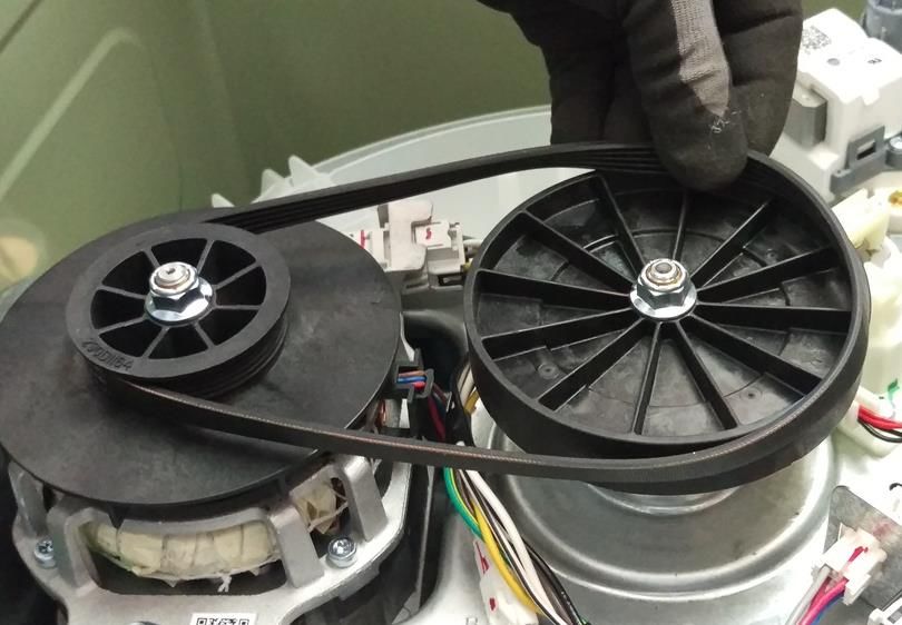
Nomenclature
The nomenclature breaks down and explains what the letters and numbers mean in the model
number

Seguridad Advertencias y

 Brand                                                         Product Type                                       Engineering Number
 G = GE                                                        R = Riser                                          0
 H = Hot Point                                                 A = 2” Cover Top Load                              1
 M = Moffatt                                                   B = 4” Cover Top Load                              2
                                                               S = Standard / Stationary
                                                               P = Portable

                 Platform:
                 W = Washer
                                                                                   Partner Type
                 D = Vented Dryer – Std
                                                                                   P = Premium Cost (color)
                 V = Vented Dryer – Long
                                                                                   H = Home Depot
                 C = Condenser Dryer
                                                                                   L = Lowes
                 H = Heat Pump
                                                                                   S = Standard
                 Z = Flat Back Dryer – Long
                                                                                   C = Contract (Hoses)
                 X = Flat Back Dryer - Std
                                                                                   M = Mabe

  G              T          W           6          8           0           B         M          K             0       W S
                                                                                                                      1

                                        Series 1, 2, 3:                                    Year:                       Color:
                                        Series 1 = 1-9                                     K = 2016                    W
                                        Series 2 = 1-9                                                                 S
                                        4 = 24” unitized
                                        7 = 27” unitized
                                        Series 3 = 1-9 Washer only

 Configuration:
 F = Front Load
 T = Top Load – Rear Control
 N = Top Load – Front Control
 U = Unitized

    Ingeniería de Servicio
                                                                     -5-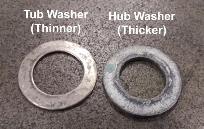
Nomenclature
The nomenclature breaks down and explains what the letters and numbers mean in the model
number

                                                                                                            Plug:
                                                              Control Type:                                 B=B
   Family                                                                                                   K=K
                                                              0 = Digital
   L = Washer (Lavadora)                                                                                    L=L
                                                              1 = Hybrid
   W = Washer Neg Elec                                                                                      T = Terminal Block
                                                              2, 3, 4, 5 = Knobs
                                                                                                            P = Without Plug
                                                                                                            S = Schuko
                                                                                                            U = UK

                                                                                Color:
                                                                                B = White (Blanco)
          Type:                                                                 G = Grey
          A = Traditional                                                       R = Red
          H = High Efficiency (HE)                                              D = Diamond Gray
                                                                                S = Clean Steel

                                                  Washing System:
                                                  0 = Infusor
                                                  1 = Agitator

                                                                                                            Engineering Number:

   L M A 7                              5         2      1          1 W G A A 0                                         0
                                                                          1
                                                                                                           Generation

                                      Capacity (Kg):
                                      52 = 25 Kg                                              Voltage /
                                                                                              Frequency
                                                                                              (V/Hz):
                                                                                              A = 120/60
                           Cabinet:                                                           B = 220/60
                           4 = 24”                                                            C = 220/50
                           7 = 27”                                                            D = 110/50
                                                                                              E = 110/60

  Brand:                                                            Lid:
  M = Mabe                                                          V = Glass
  E = Easy                                                          C = Metallic
  C = Centrales                                                     S = Metallic Soft Close
  T = Cetron                                                        W = Glass Soft Close
  G = GE

   Ingeniería de Servicio
                                                               -6-
Serial Number and Mini Manual Location
Serial Number
The Serial Number breaks down and explains what the letters and numbers mean in its
structure:
Example of Serial Number: LG312345C
The first two characters of the serial number identify the month and year of manufacture: LG =
June, 2016
A = JAN A = 2013
D = FEB D = 2014
F = MAR F = 2015
G = APR G = 2016
H = MAY H = 2017
L = JUN L = 2018
M = JUL M = 2019
R = AUG R = 2020
S = SEP S = 2021
T = OCT T = 2022
V = NOV V = 2023
Z = DEC Z = 2024
The letter designating the year repeats every 12 years
The third character denotes the product being produced: 3 = Washer (Saltillo, Mexico)
Character 4 thru 8 will denote the number of units built for a given product and will start with
00001 at the beginning of each fiscal month and progress sequentially until 99,999 is
reached or the fiscal month has changed.
Character 9 will denote the Brand and Manufacturing site of final assembly: (Saltillo, Mexico:
C = GE, M = Signature, H = HPT)
The Model Serial ID Tag is located on the right top edge of the backsplash (left top edge from
back view).
The Mini Manual is in a storage bag inside the cabinet at bottom back side.
Ingeniería de Servicio
-7-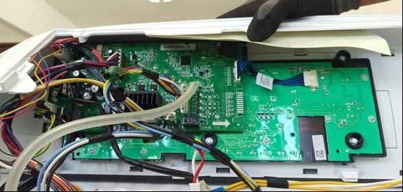
Serial Number and Mini Manual Location
Serial Number
The Serial Number breaks down and explains what the letters and numbers mean in its
structure:
Example of Serial Number: 1606S12345
The first two characters of the serial number identify the year of manufacture: 16 = 2016.
The next two characters identify the month of manufacture: 06 = June
Next character denotes the product being produced: S = Washer (Saltillo, Mexico)
Next five Characters will denote the number of units built for a given product.
The Model Serial ID Tag is located on the right top edge of the backsplash (left top edge from
back view).
The Mini Manual is in a storage bag inside the cabinet at bottom back side.
Ingeniería de Servicio
-8-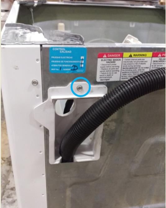
Technical Specifications

                           MOTOR
Motor Type (HP)      Voltage / Freq       Resistance (Ω)
      1/4          110-127V/50-60Hz         4.50 - 4.98
      1/4          220-240V/50-60Hz        14.48 - 16.01
      1/3          110-127V/50-60Hz         3.75 - 4.15
      1/3          220-240V/50-60Hz        11.10 - 12.26
      1/2          110-127V/50-60Hz         3.10 - 4.10

                     Mode Shifter
Voltage (V)                120                 220
Frequency (Hz)              60                  60
Power (W)                   4                   4
Current (mA)                35                  35
Resistance (Ohm)      5,700 +/- 10%       24,500 +/- 10%

           LID LOCK SWITCH
   Voltage (V)     Resistance (Ohms)
       120               60 - 90
       220              155 - 200

                            PUMPS
Function               Voltage / Freq         Resistance (Ω)
Drain Pump              120V / 60Hz             13.2 ± 0.8
Drain Pump              110V / 50Hz             20 ± 10%
Drain Pump              127V / 60Hz             20 ± 10%
Drain Pump              220V / 50Hz            120 ± 10%
Drain Pump              220V / 60Hz             65 ± 10%
Recirc Pump             120V / 60Hz             31.7 ± 1.9

  Ingeniería de Servicio
                                        -9-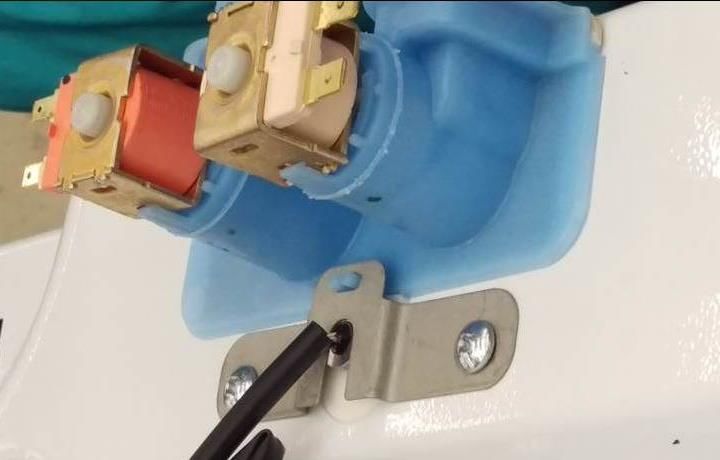
WATER VALVES
Family     Valve Type       Voltage (V)       Frequency (Hz)   Resistance (Ohms)
            Hot Side            120               50 - 60         1515 ± 10%
           Cold Side            120               50 - 60         1374 ± 10%
            Hot Side           220               50 - 60         5766 ± 10%
            Cold Side          220               50 - 60         5766 ±   10%
         Detergent (Hot)       120               50 - 60         1515 ±   10%
         Detergent (Cold)      120               50 - 60         1374 ±   10%
 27"
          Spray (Cold)         120               50 - 60         1515 ±   10%
         Softener (Cold)       120               50 - 60         1374 ±   10%
         Detergent (Hot)       220               50 - 60         5766 ±   10%
         Detergent (Cold)      220               50 - 60         5766 ±   10%
          Spray (Cold)         220               50 - 60         5766 ±   10%
         Softener (Cold)       220               50 - 60         5766 ± 10%
            Hot Side           120               50 - 60         1000 ±   10%
            Cold Side          120               50 - 60         1000 ±   10%
 24"
            Hot Side           220               50 - 60         3670 ±   10%
            Cold Side          220               50 - 60         3670 ±   10%

 Ingeniería de Servicio
                                     - 10 -
Model Graphics
Ingeniería de Servicio
- 11 -Lid Assembly Removal
Remove the two Philips head
screws of one Hinge (Right or Left
side).
Slide the lid toward the Hinge
Removed and lift it up to remove
Ingeniería de Servicio
- 12 -Control Panel Assembly Removal
To remove the control panel assembly, first remove the lid assembly.
Remove the three Philips head
screws that secure the control
panel assembly to the top cover
at front.
Remove the seven ¼ in. hex head
screws from the back panel and
remove it.
Remove the two ¼ in. hex head screws
from the rear corners on the control panel
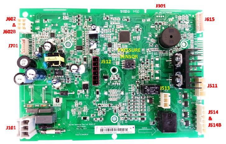
IMPORTANT.- Do not move the control panel until disengaging the pressure tube from
the control board, otherwise the pressure sensor could be damaged.
Ingeniería de Servicio
- 13 -Grasp the control panel and
push it a little toward the front of
the washer in order to see the
pressure tube.
To disengage the pressure tube
from the control board, grasp the
tube where it connects to the
pressure sensor on the board.
Twist the tube while pulling it off
the sensor
IMPORTANT.- Pressure tube
should not be handled vertically
or horizontally as there is a risk
of damage to the pressure
switch, only must disengage as
indicated above.
Disconnect connectors from the
control board and remove six ¼
in. hex screws securing the
control board bracket to the
control panel assembly and
remove.
IMPORTANT.- When reinstalling the control panel assembly, ensure that all ground
wires are reconnected and tested for proper continuity to the ground terminal on the
power cord.
Ingeniería de Servicio
- 14 -Lid Hinge
Video Link
Hinge removal can be achieved without removing the top cover or disconnecting the
control panel assembly completely.
Remove the lid assembly.
Disengage the control panel from the top cover and slide toward the rear to expose the
hinge mounting screws.
Remove the two ¼ in. hex head hinge
mounting assembly screws
Remove the Philips head screw from the
top cover.
Ingeniería de Servicio
- 15 -Slide a hand between the tub cover and the top
cover.
Grasp the hinge assembly and remove it from
under the top cover.
Ingeniería de Servicio
- 16 -Lid Lock Striker
Video Link
The lid lock striker slides into the lid
lock/switch assembly. When a cycle is
started the lock assembly engages with
the striker preventing the lid from opening
during the cycle.
The latch has spring tension on it to keep it
engaged with the switch/lock assembly
Ingeniería de Servicio
- 17 -To remove the striker from the lid:
Open the lid.
Using a small screwdriver, insert it into
the small hole below the striker.
Push inward gently on the locking tab
and turn the striker to the left
Pull the striker from the lid
Ingeniería de Servicio
- 18 -Lid Switch/Lock Assembly
Video Link
The lid lock and switch are together in
one part. It requires 120 VAC to activate
the lock.
The approximate resistance of the lock
coil is 70 ohm from Blue – Black from
J513 board connector (at Lid Lock closed
position)
Checking between Black and White wires
at the same board connector will show the
continuity of the lid switch.
To remove the lid switch/lock assembly:
Ingeniería de Servicio
- 19 -Remove the bezel from the top cover by
reaching under the top cover toward the
lock assembly and feel for the bezel tabs
to extend through the lock body.
Push the tabs out from the side of the
lock body and then push up to
remove the bezel from the top cover
Ingeniería de Servicio
- 20 -Using a small screwdriver, push down
gently on the tab that prevents the lock
assembly from sliding.
Slide the lock assembly to the left first to
disengage the right tab, then slide to the
right allowing the lock assembly
disengage from the top cover.
Pull the lock assembly from under the
top cover and disconnect the harness
connector.
Ingeniería de Servicio
- 21 -Two Coil Water Valve
Turn water supply off to valve. Hoses do
not need to be disconnected at this time.
Remove two Phillips head screws that go
through the thermistor mounting bracket
into the body of the valve.
Remove thermistor by pulling up on lip of
thermistor. Ensure o-ring is removed with
thermistor.
Ingeniería de Servicio
- 22 -Tilt back of valve up and slide out of top cover.
Once valve is out and held over the basket,
disconnect hoses.
Valve, funnel and Gasket are one part.
Ingeniería de Servicio
- 23 -Four Coil Water Valve On GTW680 Model
Video Link
To remove the water valve:
Shut off the water supply to the
washer. Hoses do not need to be
disconnected at this time.
Lean the control panel assembly
back. It does not have to be
completely removed.
Disconnect the harness from the
water valve.
Ingeniería de Servicio
- 24 -Remove three ¼ in. hex head screws
securing the valve to the top cover and
pull the valve up.
Hold valve over the basket and
disconnect the supply hoses from the
valve.
Quad Valve and the four rubber seals
are together in the same part number
Ingeniería de Servicio
- 25 -Thermistor Removal
After the water valve is removed, the
thermistor can be accessed and
remove.
It is pushed into the dispenser box
and held in place by the water valve
and is sealed with an O-ring.
Remove thermistor by pulling up on
lip of thermistor. Ensure O-ring is
removed with the thermistor.
Ingeniería de Servicio
- 26 -Dispenser Removal
The dispenser hold detergent and
fabric softener and delivers it at
precise times for the cycle selected.
Water is added to the dispenser from
the water valve to fill and flush the
cups. After the valve turns off the
remaining water in the cup siphons
out.
Video Link
When bleach is added to the bleach
cup it is funneled through to the tub
cover and into the tub.
Remove the backsplash assembly,
water valve and top cover.
Remove the dispenser tray from the
dispenser body.
Remove four ¼ in. hex head screws
from the top cover securing the
dispenser body to the top cover
Ingeniería de Servicio
- 27 -Remove the dispenser body from the
top cover by pushing back slightly on
the dispenser body and pull away
from top cover.
Take care of the back tap of the dispenser body in
order to not damage it.
The dispenser shower insert can be
removed at this time for cleaning if
necessary.
Dispenser Shower Insert
Ingeniería de Servicio
- 28 -Top Cover Removal
Remove the lid assembly and control panel assembly.
.
Disengage the power cord from the top
cover by pulling up on the front of the
power cord grommet.
Slide the power cord grommet forward
Ingeniería de Servicio
- 29 -Pull up off of the top cover.
Remove ground screws.
Slide the harness grommet out toward
the rear of the washer
Ingeniería de Servicio
- 30 -The harness grommet for the lid lock
does not need to be removed unless
replacing the top cover.
If replacing the top cover, squeeze
the two clips on the grommet and
push it through the opening. Transfer
to the new cover
Remove lid assembly and the control panel
assembly.
Remove two ¼ in. hex head screws (one on
each side) at the rear corners of the top
cover.
Slide the harness grommet out toward the
rear of the washer.
Disengage the power cord from the top
cover by lifting up on the front of the cord
grommet, slide forward and up off of the top
cover.
Raise the rear of the top cover up, then pull
forward slightly to disengage from the front
clips that secures the front of the top cover
to the cabinet.
Ingeniería de Servicio
- 31 -Impeller and Agitators
Single Action Dual Action
Agitator Agitator Impeller
Ingeniería de Servicio
- 32 -Impeller
To remove the impeller, pop the
center cap off with a small flat
screwdriver to access the 7/16th in.
hex bolt.
The splined coupler is part of the
impeller and agitators.
Note.- Impeller bolt should be
replaced any time it is removed for
service and torqued to 100 in.lbs.
If it is necessary, use a couple of nose pliers in order
to disassemble the impeller.
Ingeniería de Servicio
- 33 -Dual Stage Agitator
To remove the dual action agitator, the cup section needs to be removed to access the
7/16th in. hex bolt. The bolt is located inside the agitator at the bottom. A long socket
extension (at least 17 in. long) will be needed to remove it.
Note.- Agitator bolts should be replaced any time it is removed for service and torqued
to 100 +/- 5 in-lbs.
Ingeniería de Servicio
- 34 -Single Stage Agitator
Remove the single action agitator by taking the agitator cap off to access the 7/16 th in.
hex bolt. The bolt is located inside the agitator at the bottom. A long socket extension
(at least 17 in. long) will be needed to remove it.
Note.- Agitator bolts should be replaced any time it is removed for service and torqued
to 100 +/- 5 in-lbs.
Ingeniería de Servicio
- 35 -Basket Removal
Remove the lid, control panel assembly and top cover.
Remove the tub cover by unclipping eight
clips around the edge and lift it off.
Ingeniería de Servicio
- 36 -Basket Removal
Remove the 1-5/16th in. hub nut by
turning the nut clock-wise to loosen
(reverse threads).
A new hub nut should be used when
reinstalling the basket assembly.
Torque to 100 +/- 10 ft.lbs.
Remove the hub washer
Right position Wrong position
Be care of position when reinstalling the hub washer.
Ingeniería de Servicio
- 37 -Lift the basket out of the tub.
Remove the tub washer.
Ingeniería de Servicio
- 38 -Tub and Cabinet Removal/Replacement
Remove the lid, control panel assembly and top cover.
Remove one Philip screw from the hose
cover.
Remove hose cover.
Ingeniería de Servicio
- 39 -Disengage the rod and spring suspension
from the tub assembly.
Ingeniería de Servicio
- 40 -Tub and Cabinet Removal/Replacement
Once the suspension is disengage, remove the
prop blocks letting the tub assembly rest on the
belt protector.
Raise the cabinet up and over the tub assembly
and set aside.
Note.- Be careful of the tub assembly balance
while removing cabinet.
Ingeniería de Servicio
- 41 -Harness Removal/Replacement
The cabinet needs to be removed to replace the
harness assembly.
Once the cabinet is removed there are two ¼ in. hex
head screws that secure the harness to the side of the
tub that need to be removed.
There is one ¼ in. hex head screw on the bottom.
Ingeniería de Servicio
- 42 -Bottom Component View
Ingeniería de Servicio
- 43 -Drain And Recirculation Pump
Recirculation pump
The GTW680 model has a recirculation pump
located at the front of the bottom of the tub. It
mounts to the tub the same as the drain pump.
Video Link
Drain Pump
The drain pump is located on the right side of the
bottom of the tub. It is mounted directly to the tub
secured by three (3) 3/8th in. hex head bolts.
Video Link
Both pumps are 120 VAC.
The approximate resistances of the pumps checked
from J512 board connector are:
Drain pump – 13.2 ohms
Recirculation pump – 31.7 ohms
PUMPS
Function Voltage / Freq Resistance (Ω)
Drain Pump 120V / 60Hz 13.2 ± 0.8
Drain Pump 110V / 50Hz 20 ± 10%
Drain Pump 127V / 60Hz 20 ± 10%
Drain Pump 220V / 50Hz 120 ± 10%
Drain Pump 220V / 60Hz 65 ± 10%
Recirc Pump 120V / 60Hz 31.7 ± 1.9
Ingeniería de Servicio
- 44 -Drain And Recirculation Pump
Once the bolts are removed, the pump can be pulled from the tub.
Have something to catch excess water. The seal is integrated to the pump as one Part
Number.
Ingeniería de Servicio
- 45 -Drive Belt
The drive belt has five ribs and
can be removed easily turning
the pulley to walk the belt off.
To reinstall the belt, put it on the
motor pulley first.
Stretch the belt around the
transmission pulley as far as it can go.
Then rotate the pulley until the belt is
in place. Be sure all the ribs of the
belt.
Ingeniería de Servicio
- 46 -Drive Motor
Video Link
There are two different horsepower
motors. One third and one half
horsepower motors. They are both
120 VAC reversible motors.
Resistances are ½ hp.- White –
Brown and White – Yellow approx.
3.1 ohm.
1/3rd hp. approx. 3.8 ohm from J511
board connector.
To remove the motor:
Remove the belt and fan pulley. The pulley is held on by a 9/16 in. lock nut.
Use a new nut when reinstalling the pulley and torque to 110 in-lbs.
Disconnect the motor harness connector.
MOTOR
Motor Type (HP) Voltage / Freq Resistance (Ω)
1/4 110-127V/50-60Hz 4.50 - 4.98
1/4 220-240V/50-60Hz 14.48 - 16.01
1/3 110-127V/50-60Hz 3.75 - 4.15
1/3 220-240V/50-60Hz 11.10 - 12.26
1/2 110-127V/50-60Hz 3.10 - 4.10
Ingeniería de Servicio
- 47 -Drive Motor
Unclip the hall/speed sensor from the
motor.
Remove two ½ in. bolt mounting the
motor to the tub letting the motor
come loose from the platform.
When reinstalling the motor mounting
bolts torque to 110 in-lbs
Note.- If the hall/speed sensor is wire tied to the motor when replacing the motor, order
both, the motor and hall/speed sensor.
Ingeniería de Servicio
- 48 -Mode Shifter Assembly
The mode shifter either engages or
disengages the clutch with the
transmission pulley depending on
whether the cycle is in spin or
agitate.
The clutch home position is
engaged with the pulley or ready for
spin.
It has a 120 VAC motor.
Resistance of the mode shift motor
from Red – Blue is 5700 +/- 10 %
ohm from J512 board connector.
To remove the mode shifter:
Remove the transmission pulley and nut. The pulley is held on by a 9/16 in. lock nut.
Use a new nut when reinstalling the pulley and torque to 110 in-lbs.
Mode Shifter
Voltage (V) 120 220
Frequency (Hz) 60 60
Power (W) 4 4
Current (mA) 35 35
Resistance (Ohm) 5,700 +/- 10% 24,500 +/- 10%
Ingeniería de Servicio
- 49 -Mode Shifter Assembly
Disconnect the mode shifter motor
harness connector.
Remove two 3/8th in. hex head
mounting bolts. This will allow the
complete mode shifter assembly to be
removed with the clutch.
The clutch spring and spring washer
will come off as well. When
reinstalling be sure to install the
spring washer before the clutch
spring.
Ingeniería de Servicio
- 50 -Platform Transmission Assembly
The platform transmission
assembly is one complete part with
the exception of two harness
connector brackets and one motor
splash guard. These will need to be
transferred to the new platform
assembly when replacing the
platform transmission assembly.
The platform assembly is secured
to the tub by nine 3/8th in. hex head
bolts circled. One of these bolts
also holds one of the harness
brackets to the platform.
To remove the platform assembly
after all other components have been
removed, remove the nine 3/8th in.
hex head bolts and pull the platform
away from the tub.
Note.- The bottom of the tub can be
used to pry the platform transmission
assembly off of the tub.
The tub seal is pressed on to the
platform transmission assembly. If
there is a leak from the seal, the
complete transmission will need to be
replaced.
Ingeniería de Servicio
- 51 -Platform Transmission Assembly
To reinstall the platform assembly
to the tub, slide the shaft of the
transmission into the opening of the
tub.
Press the tub seal into the tub
opening.
Note.- Line the guide post with the
opening in the platform.
Tighten the nine hex head bolts in
a crisscross pattern so that the seal
is pulled into the tub evenly and
securely
This is done by tightening each bolt about ¼ of the way in at a time.
Torque to 70 in-lbs.
Ingeniería de Servicio
- 52 -Schematic
Ingeniería de Servicio
- 53 -Control Board User Interface
Ingeniería de Servicio
- 54 -Display Test and Fault Chart
Binary Display Fault Chart
Fault # Test # Fault / Test # displayed
Fault / Test displayed on displayed on in binary format using
number 7-segment 7-segment cycle status ligths
display display Filled circles indicate
light on
0
1 E1 t1
2 E2 t2
3 E3 t3
4 E4 t4
5 E5 t5
6 E6 t6
7 E7 t7
8 E8 t8
9 E9 t9
10 EA tA
11 EB tB
12 EC tC
13 ED tD
14 EE tE
15 EF
16 EG
17 EH
18 EJ
19 EL
20 En
21 EP
22 Er
23 Et
Ingeniería de Servicio
- 55 -Service Mode Entry
SERVICE MODE ENTRY
Family Mode Entry Function
Kraken Cycle selection knob in "BASKET The cycle selection knob is now used to
27" CLEAN" position. control the test selection menu
knobs
Unplug Washer. Plug washer. During Once the test number is selected,
10 first seconds press and hold pressing Start will begin the selected test
START/PAUSE + MANUALS buttons
by 2 seconds Field service mode will time out after 5
minutes if there is no user activity
Kraken Cycle selection knob in "BASKET The cycle selection knob is now used to
27" CLEAN" position. control the test selection menu
hybrid
Unplug Washer. Plug washer. During Once the test number is selected,
10 first seconds press and hold SPIN pressing Start will begin the selected test
+ EXTRA SPIN buttons by 2 seconds
Field service mode will time out after 5
minutes if there is no user activity
Ingeniería de Servicio
- 56 -Service Mode Tests
Service Mode Test
Knob Index / Test
number (Displayed
on SSD, 7-segment
display, if present)
Test Test Name Description of test
(Without SSD will
be displayed in
binary format. (See
Binary Chart)
1 t1 Cold Water Valve Pressing Start will toggle the cold
water valve on and off. Test will
have a timeout for how long
valve will be on (1 minute). The
valve will turn off when the test
is exited
2 t2 Hot Water Valve Pressing Start will toggle the hot
water valve on and off. Test will
have a timeout for how long
valve will be on (1 minute). The
valve will turn off when the test
is exited
3 t3 Fabric Softener "Pressing Start will toggle the
Dispenser fabric softener valve on and off.
Test will have a timeout for how
long valve will be on (1 minute).
The valve will turn off when the
test is exited
4 t4 Spray Rinse Valve "Pressing Start will toggle the
Check spray rinse valve on and off.
Test will have a timeout for how
long valve will be on (1 minute).
The valve will turn off when the
test is exited
5 t5 Mode Shifter "Pressing Start will start the test.
The lid must be closed to start the
test. If lid is opened the Locked
LED will blink.
When started, the mode shift to
spin will occur if required and the
lid will be locked.
When mode shift is complete, the
washer will begin spinning
6 t6 Drain Pump Pressing Start will toggle the
Ingeniería de Servicio
- 57 -drain pump on and off
7 t7 Lid Lock the lid will be locked
8 t8 Pressure Sensor "Pressing Start will start the test,
valves will turn on.
SSD will show water level (for
example 1.5in H2O, shows 15).
Knob models will blink 1 LEDs
for each 0.5"
Water valves shut off at 2.0"
level
9 t9 hall sensor/ Pressing Start will start the test.
TRIACS The washer will begin agitating
in both ways in order to validate
pulses read by the hall sensor and
triacs performance
10 tA Lid Switch "SSD or LEDs (knob models)
shows lid status:
"LO" for Lid Opened
K27 LEDs: Soak30 +
Soak60.
"LC" for Lid Closed
K27 LEDs: Pause + Spin.
11 tB Recirculate Pump Pressing Start will toggle the
recirculation pump on and off
12 tC Software Version Shows the Software version in
Display or LEDs
13 tD Personality ID Shows the Personality ID in
Display or LEDs
14 tE Exit Service Mode Pressing Start will exit Service
Mode
Mode Tests
Ingeniería de Servicio
- 58 -Fault Codes
FAULT CODES KRAKEN
Fa Fault K K Fault Repair Action Volatil Component Root Cause
ult Code 2 2 Description e/
nu 4 7 Non
mb Volatil
er e
1 E1 X Speed > 60 * Reset Volatile Non A) Lid lock A) Lid Lock Opened /
rpm in fault Volatil unplugged
Speed * Run Service e B) Striker
Sensor with Mode Test 7. B) Striker Broken
Lid * Monitor a wash C) Lid lock
unlocked cycle to verify that Harness C) Harnesses False
everything works contact / lid lock
properly Harness Damaged
Customer moves the
Basket (while
cleaning, etc)
2 E2 X Motor * Disconnect Non Control A) Control Board Triac
turned off & washer and wait Volatil Board damaged
speed does the basket stops e
not slow * Connect the
down washer and reset
fault
* Running service
mode routine
(test 9)
* If there is
damage in
Control Board, it
will display E7, if
no damage, the
machine will work
properly.
3 E3 X X Motor * Reset Non Non A) Speed A) Sped Sensor does
turned on & Volatile fault Volatil Sensor not connect, bad
Speed * Check that the e assembly, harness
Sensor transmission is B) Motor damaged
does not not forced B) Motor thermal
detect * Check that C) Capacitor protection opened.
movement clothes are not
stuck D) C) Capacitor o motor
* Running service Agitator/infus unplugged
mode routine er
(test 9), if you D) Clothes stuck in
have E3 again E) Basket or Agitator
check following Transmission
points: E) Transmission
a) Verify that damaged
Ingeniería de Servicio
- 59 -Speed Sensor is
connected
b) Check the
motor and
capacitor are
connected
c) Check Motor
thermal
protection, check
Motor has
continuity.
* If the above
points are correct,
then monitor a
wash cycle to
verify that
everything works
correctly.
4 E4 X The lid lock * Reset Non Non A) Lid lock A) Lid lock damaged
does not Volatile fault Volatil
lock or lock * Running service e B) Lid lock B) Lid lock bad
after 10 mode routine Harness connection
attempts. (test 7)
* Check Lid Lock C) Striker C) Lid lock Harness
connections damaged
* Check that the
Lid Lock Striker is
not broken or
improperly
assembled.
* Run service
mode routine
again (test 7) in
case of failure
replace lid lock
switch,
* Run service
mode routine
again (test 7) in
case of failure
replace Control
Board.
* monitor a wash
cycle to verify that
everything works
correctly.
5 E5 X X Speed > * Reset Non Non A) Band A) Band disassembly
1000 rpm Volatile fault. Volatil B) Motor B) Motor pulley
* Check that the e pulley loose nut
band is B) B) Transmission
assembled Transmission pulley loose nut
Ingeniería de Servicio
- 60 -correctly. pulley
* Running a
manual cycle
"only spin".
6 E6 X X Safety relay * Reset Non Non A) Control A) basket moving at
short circuit Volatile fault Volatil Board the beginning of the
* Wait 10 e cycle
seconds
* Running service
mode routine
(test 9), if you
have E6 change
Control Board
7 E7 X X Triacs short * Reset Non Non A) A) Overcurrent due to
circuit Volatile fault Volatil Agitator/Infus clothes stuck between
* Check that the e er basket or agitator
transmission is
not forced B) B) Transmission
* Check that Transmission damaged
clothes are not
stuck C) Control C) Control Board triac
Running service Board damaged
mode routine
(test 9), if you
have E7 again
then replace
Control Board
8 E8 X X water level * Reset Volatile Volatil A) Low A) Water exceed the
increased at fault. e pressure maximum allowed.
maximum * Check water + It is filled with hose
level valves for leaks B) Water
allowed * Verify that the Valve + It is filled with water
(Overflow) user has not filled at a high level and
the washing C) pressure then clothes are
machine with switch hose placed.
hose.
* If the Washer B) Valves do not cut
with no water water flow
repeats the fault
then verify and C) Pressure switch
correct: hose clogged or
a) Check the collapsed in the
pressure switch routing
hose is not pressostat Hose with
collapsed no water
restrictions in all (pressure switch hose
its routing. assembled with water
b) Check the in the tub)
pressure switch
hose no water
inside.
Ingeniería de Servicio
- 61 -Running service
mode routine
(test 8)
9 E9 X X Valves turn * Reset Volatile Volatil A) Water low A) No water in pipes/
on for a fault e pressure Very low pressure 15
certain time * Verify that there B) Inlet seconds per liter at
and no level is water in the hoses water supply pipes.
change is supply pipe. C) Water Inside Washer 30
detected * Check supply valves seconds per liter
hoses are D) Pressure
connected. switch hose B) Clogged water
* Check that the E) Water valves filters
water supply valve
valves are open. F) Valve C) Filling hose
* Check that harness disconnected /
valves filters are G) Control inverted
clean Board
D) Pressure sensor
Running service Hose disassembled or
mode routine collapsed.
(test 1-4),
verifying that E) valve does not cut
each valve is flow
activated and
water ingress. if F) Harness
water does not disconnected or
entry: inverted valves
* Check harness
connections. G) Control Board
* Measure
resistance at the
valve terminals
disconnected
measuring a
value of 1000 for
127VAC Ohm
and 3670 Ohm
for 220VAC.
outside this
range, change
valve
In case if water
enters, then run
Service mode
routine (test 8) if
displays error 9,
check:
* Check the
Ingeniería de Servicio
- 62 -pressure switch
hose have no
restrictions or
pinches in the
area of the upper
cover Grommet.
* Check that the
hose pressure
switch has not
accumulated or
trapped water.
* Check the
pressure switch
hose is not
perforated.
In case if water
enters, running
service mode
routine (test 8), If
displays E9 then
replace Control
Board
10 EA X X Pressure * Reset Non Non A) Pressure A1.- It has been
sensor out Volatile fault Volatil Sensor hose assembled pressure
of range * Reassembling e B) Control sensor hose having
the Pressure Board water inside the tub.
Sensor hose
ensuring that the A2.- Pressure Sensor
Tub is empty, hose restricted
verifying that the
pressure switch B) Control Board is
hose has not not working
accumulated or
trapped water.
* Running service
mode routine
(test 8)
* If the failure
repeats, then you
must change the
Control Board
11 EB X X Pressure * Reset Non Non A) Pressure A) bad routing sensor
Sensor Volatile fault Volatil Sensor hose hose / Disassembled
hose is * Check that the e B) Tub
disconnecte hose is C) Control B) tub Pivot Broken
d during the connected to the Board
wash cycle pressure sensor C) Control Board is
and the Tub. not working
* Check that the
hose is not
perforated
Ingeniería de Servicio
- 63 -* Check the
pressure sensor
hose has no
water inside.
Running service
mode routine
(test 8) and verify
there is no fault
E9
12 EC X X Pump on * Reset Non Non A) Drain A) Clogged pump
and not Volatile fault Volatil Pump
reduced Check in only e B) Draining pump
water level. spin if the water D) Pump protected from
level low, if not: Harness overheating
* Check
connections to E) Pressure C) Drain pump
the pump Sensor Hose damaged
* Check
connections to F) Control D) pump harness
the control board Board damaged
* Check that there
is no foreign E) Pressure sensor
material clogging hose bent
the pump
* Check that the F) Control board does
pump is not not detect level
protected from change
overheating
* Check that the
pump is not
damaged.
If the water go
down and the
failure occurs:
* Check the
pressure sensor
hose have no
restrictions or
pinches in the
area of the upper
cover Grommet.
* Check that the
pressure sensor
hose has not
accumulated or
trapped water.
Add water again
and Check in only
spin
Checking the
above points and
Ingeniería de Servicio
- 64 -seeing if the
water level downs
and presents the
fault, change
control board
13 ED X X Disturbance * Reset Volatile Volatil Control 1.- Sources of noise in
power line fault. e Board or near the electrical
* ask if the line, such as arc
product is at or welding, drilling, etc.
near the same
line as noise
sources.
* Check the
connection from
the wall outlet to
power cord
* If there are no
noise sources
and present the
fault permanently
change Control
Board. In case of
any failures,
review electrical
installation.
14 EE X X Disturbance * Reset Volatile Volatil Control 1.- Sources of noise in
power line fault. e Board or near the electrical
* ask if the line, such as arc
product is at or welding, drilling, etc.
near the same
line as noise
sources.
* Check the
connection from
the wall outlet to
power cord
* If there are no
noise sources
and present the
fault permanently
change Control
Board. In case of
any failures,
review electrical
installation.
15 EF X X Code fault * Reset Volatile Volatil Control 1.- Sources of noise in
Corrupted fault. e Board or near the electrical
* ask if the line, such as arc
product is at or welding, drilling, etc.
near the same
line as noise
Ingeniería de Servicio
- 65 -sources.
* Check the
connection from
the wall outlet to
power cord
* If there are no
noise sources
and present the
fault permanently
change Control
Board. In case of
any failures,
review electrical
installation.
16 EG X X Memory * Reset Non Non Control 1.- Memory failure
failure Volatile fault Volatil Board
* Running a e
washing cycle as
confirmation.
* Replace Control
Board
21 EP X X Pressure * Reset Non Non Control 1.- pressure sensor
sensor Volatile fault. Volatil Board bad assembly
disconnecte * Check that the e
d from the pressure sensor
Control is not
Board disassembled
from Control
Board.
* Check that there
is no waste of
tartar between
Pressure Sensor
pins
* Disconnect and
connect hose
pressure sensor
hose ensuring
that the ink is
empty.
* Running a
washing cycle as
confirmation.
* If the fault
occurs again,
then you should
replace the
Control Board.
Ingeniería de Servicio
- 66 -23 Et X X Control * Replace Control Volatil Control 1. manufacturing
Board not Board e Board process Error
parameteriz
ed
Codes
Codes
Ingeniería de Servicio
- 67 -Cycle Overview
Kraken_27_Models
Ingeniería de Servicio
- 68 -You can also read