Humidity Control for HV Battery Systems - Leadership in Filtration - Mann+Hummel
←
→
Page content transcription
If your browser does not render page correctly, please read the page content below
Humidity Control
                           for HV Battery
                           Systems

Leadership in Filtration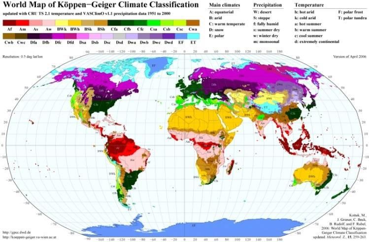
2   M A N N +HUMME L          HUMIDITY CONTROL FOR H V BAT T E RY SYST E MS

    Authors
    ››› Dr. Michael Harenbrock, corresponding author (michael.harenbrock@mann-hummel.com)
    ››› Dr. Stefan Kunze
    ››› Stephan Niemeyer

    Summary
    As HV battery systems for PHEV and BEV cannot be her-              Keywords:
    metically sealed to avoid housing deformation caused by              ››› safety
    pressure differences between environment and system inte-            ››› pollution
    rior, pressure balancing is required. Semi-permeable PTFE            ››› lithium battery
    membranes offer a suitable solution as they let gases pass           ››› EV (electric vehicle)
    while holding back particles and liquids. An emergency               ››› component
    degassing function can be integrated, reducing overall sys-
    tem complexity. To prevent water vapor condensation at
    cooling surfaces inside the battery system, an adsorption
    unit is applied to reduce the risk of corrosion and electric
    shorts, especially in hot and humid climates. Calculation
    tools for product dimensioning were developed.

    1. Motivation

        Climate change is one of the major threats to mankind.             Consequently, forecasts show a strongly increasing need
    Acknowledging this, the COP21 Conference in Paris has              for locally zero-emission vehicles (xEV)6, namely Plug-In
    agreed on a target of maximum 1.5°C temperature rise com-          Hybrid Electric Vehicles (PHEV) and Battery Electric Vehi-
    pared to the pre-industrial levels to limit the negative effects   cles (BEV)
    of global climate change1. CO2 emissions from transport                High-Voltage (HV) Li Ion batteries will be used for xEV
    globally account for 23% of the total CO2 emissions2. Some         powertrains in the years to come7. To enable sufficient elec-
    countries are already planning to ban vehicles powered by          tric driving ranges, chemistries leading to high volumetric
    Internal Combustion Engines (ICE) from entering cities or          energy density are employed. These cells need an environ-
    even completely to achieve these targets (e.g. India, Norway,      ment that protects them from high / low temperatures and
    Netherlands)3. As the decrease of battery pack cost is faster      from contamination by particles or liquids, ensuring the
    than expected4, OEMs believe a cost break-even between             required lifetime and preventing malfunctions.
    xEV and ICE which meet the more stringent NOx and PM2.5
    emission targets can already be reached in the 2021 – 2023
    time frame5. As a first step, 48V Hybrids will enable “Electri-
    fication for the masses”.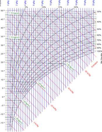
H U MI DI T Y CONT ROL FOR H V BAT T E RY SYST E MS MANN+ H U MM E L 3 2. Problem description It is not possible to seal the battery system housing hermeti The pressure balancing device has to efficiently hold back cally for total protection, as this would lead to mechanical liquids and particles and let gas pass. Established solutions stresses on the housing caused by pressure differences for this are e.g. vents and units with semi-permeable mem- between environment and the HV battery system interior. If branes. As gas enters the battery system interior, humidity these exceed a maximum value depending on the battery can also enter. If the surface temperature of e.g. cooling system design (e.g. thickness of the housing´s walls, required plates falls below the dew point, condensation on those cold sealing forces), the resulting forces will lead to plastic defor- surfaces inside the system will occur. So an additional device mation or even breaking of housing parts. Reduced com- is required to prevent condensation. pression of sealings can also result in leakages. To avoid this, pressure balancing is required. Figure 1: Battery System without pressure balancing Figure 2: Battery System with pressure balancing
4 M A N N +HUMME L HUMIDITY CONTROL FOR H V BAT T E RY SYST E MS
3. Humidity control
3.1 Protection against liquid water 3.1.2 Material selection
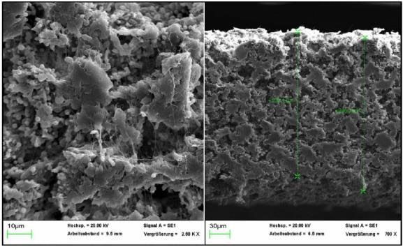
3.1.1 Concept A PTFE membrane was validated for this application.
The material is very durable, enabling lifetime applications.
To reduce the system complexity, two important functions – As the fluorinated membrane´s low surface energy leads
pressure balancing and emergency degassing – are com- to repulsion of particles and liquids, the risk of clogging is
bined into one unit. The unit has to ensure that no liquid minimized as long as the part is mounted in such a way that
water can enter the battery housing under all conditions. the membrane is oriented vertically or facing downwards.
Another benefit is the independence of material properties
to temperature changes, which also enables to use of the
membrane in a degassing device.
Figure 3: SEM picture PTFE membrane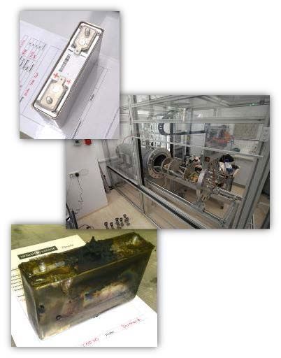
H U MI DI T Y CONT ROL FOR H V BAT T E RY SYST E MS      MANN+ H U MM E L   5

3.1.3 Product design

The pressure balancing unit has to be designed in a way that       This can be calculated using the known density of air ρ:
allows the necessary air exchange and ensures that the                               Tn
required protection class is reached, e.g. according to            			         ( )( )
                                                                   ρ(p,T) = ρn * ρ *
                                                                                 ρn  T                                        (1)
ISO 20653. Pressure differences between the environment
and the battery system interior can result from differences in         where ρn, pn and Tn are the reference values (1.18kg/m³,
air temperature and change in altitude during driving or air       288.15K = 15°C, and 1013mbar, respectively). The air mass m
transport. While the gas exchange is enabled for pressure          is calculated with formula (2):
balancing, the battery system has to be protected from con-
                                                                   m = V* ρ(p,T)        (2)
tamination from solids, e.g. dust, particles, liquids / water,
and direct contact of the battery cell, e.g. by wire, also after
                                                                       In a closed system the air mass inside is constant, so any
a thermal incident. Water ingress during driving can happen
                                                                   rise in T must be balanced by a rise in p in order to keep the
through splash water or wading while passing a brook. Fur-
                                                                   density constant. As the housing can only withstand a max-
ther risks are flooding events and steam-jet cleaning of the
                                                                   imum force resulting from the differential pressure ∆p to the
HV battery system.
                                                                   outside, the semi-permeable membrane of the degassing
    The required membrane area can be calculated based on
                                                                   unit enables the flow of air mass in and out of the battery
    ››› membrane permeability
                                                                   housing. Likewise, when the ambient (outside) pressure
    ››› maximum allowed pressure difference between
                                                                   changes, the resulting ∆p will have to be limited by allowing
         environment and HV battery system
                                                                   gas exchange via the membrane.
    ››› free air volume inside the battery system
                                                                       The amount of gas exchange via the membrane is pro-
    ››› maximum expected changes in altitude during
                                                                   portional to the permeability P of the membrane, the mem-
        driving and transport
                                                                   brane area A, and the driving pressure difference, ∆p
    ››› maximum expected temperature differences

    To calculate the required membrane area for pressure
                                                                   ( dm
                                                                     dt ) = P · A · ∆p             (3)

balancing, the maximum pressure change the system can be
                                                                      The permeability is characteristic for the chosen mem-
submitted to must be calculated.
                                                                   brane material, the maximum ∆p together with the rate of
    At a given time, the battery system contains a mass of
                                                                   pressure change, is usually customer-specific, as a result of
air m, depending on
                                                                   temperature and/or altitude changes. Examples:
    ››› the free volume V inside the battery,
                                                                      ››› from -20°C to 65°C in 60 minutes,
    ››› the temperature T, and
                                                                      ››› hill climbing from 0m altitude to 2.500m altitude
    ››› the pressure p.
                                                                           in 45min, or
                                                                      ››› air transport, from 0m altitude to 10.000m altitude
                                                                          in 15min

                                                                      Often the air transport poses the greatest challenge.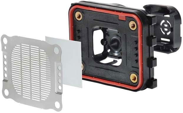
6   M A N N +HUMME L         HUMIDITY CONTROL FOR H V BAT T E RY SYST E MS

    Figure 4: Calculated pressure changes caused by air transport

    These requirements translate to an either positive or nega-
    tive rate of change of the differential pressure (d∆p/dt) to
    the outside. The partial differential equation for ∆p (4) can
    be integrated in time to yield the required membrane area A.

                             1     dm     d∆p
    ∆p(t) = ∆p(t – ∆t *) + p · A · dt ∆t + dt · ∆t           (4)

    To avoid any damage to the battery system housing and
    seals, the membrane area has to be large enough to ensure
    that ∆p(t) < ∆pmax as specified by the customer or battery
    manufacturer at all times.
    The membrane´s water repellence in combination with seal-
    ing concept, protection cap and supporting grid prevent
    water ingress even under challenging head-on steam-jet
    cleaning, reaching protection class IP6K9K, according to
    ISO 20653. A further point to consider is a potential reduction          Figure 5: Simulating thermal
    of the effective permeability of the membrane during lifetime.           runaway of Li Ion battery cells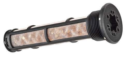
H U MI DI T Y CONT ROL FOR H V BAT T E RY SYST E MS        MANN+ H U MM E L   7

3.1.3.2 Emergency Degassing

The HV battery system consists of a large number of battery          Considering that the temperature at which the gas is
cells. In the case of overheating of a battery cell, a thermal    released is much higher (several 100 °C), the gas volume can
runaway reaction can occur.                                       reach 200 - 300 liters per cell. Considering a typical free air
    Possible reasons are short-circuiting caused by a dam-        volume inside the battery system of 50 liters, even degas-
aged battery separator, severe overcharging, and evapora-         sing of one cell will lead to high overpressure inside the sys-
tion / breakdown of the electrolyte8. The evaporated electro-     tem. The situation can become even more critical if the dam-
lyte can catch fire, leading to violent chemical reactions        aged battery cell initiates thermal runaway in adjacent
releasing large amounts of extremely hot gas in a very short      battery cells, multiplying the negative effect. In order to pre-
time. The trigger point for this thermal runaway depends on       vent this, the housing must provide a degassing function
the Li Ion chemistry used. The dilemma: the cells which are       which opens quickly to avoid massive pressure build-up and
safest, i.e. show the highest trigger temperature have the        enables fast pressure relief through a sufficiently large open
lowest energy capacity. The chemistries favored in passen-        area to the outside. One possible solution is the classic pres-
ger cars are the ones which lower trigger temperatures9. So       sure relieve valve. It is advantageous to integrate this func-
to prevent thermal runaways from happening, an efficient          tion into the pressure balancing unit.
thermal management is required. The amount of gas                    The membrane will be bulged towards a contact pin
released during thermal runaway strongly depends on               during gas formation. It will contact the base plate of the
chemistry used, cell size and the cell´s state of charge10,11.    unit in the course of its outward deformation. A sharp pin on
Comparative results show that up to 70-100 norm liters (i.e.      the inside of the base plate will cause the membrane to rup-
at standard temperature and pressure) can be released from        ture at a specified overpressure, immediately opening the
one xEV cell.                                                     whole area for free flow from the battery housing to the out-
                                                                  side, and therefore limiting the overpressure in the housing
                                                                  during the thermal runaway of one single cell to a safe value.

Table 1: Results from thermal runaway                             Figure 6: Pressure balancing unit with degassing function
testing of Li Ion battery cells10,11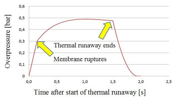
8   M A N N +HUMME L         HUMIDITY CONTROL FOR H V BAT T E RY SYST E MS

    The membrane´s almost temperature-independent mechani-              In the end, the larger of the two areas from the two cal-
    cal properties enable pressure relief over a broad range of      culated scenarios – pressure balance and pressure relief - is
    ambient temperatures.                                            chosen as the minimal required membrane area. Other sce-
       To calculate the required membrane area for degassing,        narios are possible, e.g. calculating the required area for
    the following information is required:                           the emergency degassing which is independent of the
       ››› gas volume released per battery cell                      membrane material, and then choosing a membrane with a
       ››› speed of gas release                                      permeability fitting to that area for the air exchange
       ››› size of the battery cell´s pressure vent                  requirements.
       ››› temperature of gas released
                                                                     3.1.3.3 Additional safety features
    A partial differential equation for the pressure difference to
    the outside similar to the formula (4) can be used to calcu-     To protect the battery system from water entry during wad-
    late the necessary membrane surface. Before the membrane         ing or flooding, a stabilization grid helps to limit the inward
    burst pressure is reached, the pressure is assumed to rise       deformation of the membrane caused by external water
    linearly. Once the membrane ruptures, the pressure increase      pressure, thus stabilizing the membrane. To protect the sys-
    from the released hot gas is counteracted by the pressure        tem during steam-jet cleaning, a protection cap with an
    drop from the flow to the outside, quickly leading to an equi-   internal labyrinth structure is used which guides the water
    librium near the maximum pressure, until after e.g. 3s no new    away from the membrane. This cap also prevents direct con-
    hot gas is produced and the curve will exponentially fall        tact, e.g. by wire. Using a metal grid in combination with
    towards the initial pressure. The maximum pressure reached       metal inserts and screws ensures contact protection even
    in the event depends strongly on the free area of the open-      after fire.
    ing which is fixed by the design, but only very weakly on the
    exact pressure at which the membrane ruptures. This brings
    benefits for the selected design.

    Figure 7: Mechanism of degassing function                        Figure 8: Pressure relief in case of degassing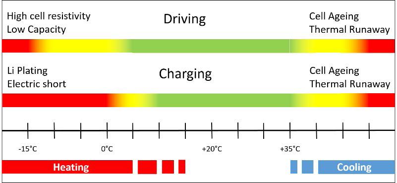
H U MI DI T Y CONT ROL FOR H V BAT T E RY SYST E MS MANN+ H U MM E L 9
3.2 Protection against water condensation
3.2.1 Concept
In addition, condensation of water on cold surfaces inside Consequently, to avoid water condensation the absolute
the HV battery system must be prevented to lower the risk humidity inside the system must be kept at a level which
of corrosion and electric shorts. The Mollier Diagram is used would not lead to crossing the dew point curve at the lowest
to visualize the relationship between relative humidity, abso- temperature inside the battery system.
lute humidity, temperature and dew point. To avoid water The risk of water condensation is especially high if liquid
condensation the absolute humidity inside the system must cooling with low coolant temperature is used for highly-
be kept at a level which will prevent the crossing of the dew efficient battery cell cooling during (fast-) charging and
point curve at the lowest temperature inside the battery (fast) driving.
system. At the dew point, the air is saturated with water, the
curve showing a relative humidity of 100% is the dew point
curve. If the temperature is lowered beyond the dew point at
constant absolute humidity, water condensation occurs.
Absolute humidity [g/kg]
Relative humidity [%]
Temperature [°C]
Dew point curve
Figure 9: Mollier diagram (illustrative)12 Figure 10: Need for cell cooling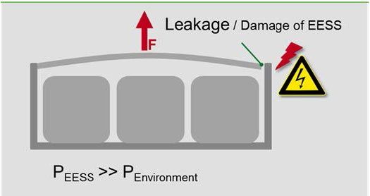
10 M A N N +HUMME L HUMIDITY CONTROL FOR H V BAT T E RY SYST E MS
3.2.2 Material selection
Favorable materials for water vapor removal are adsorbents.
Silica gel and zeolites can be used. Silica gel can bring bene-
fits in cost and performance, binding up to 40 weight-% of
water. Desorption can also be realized at much lower tem-
peratures compared to zeolites. Desorption also takes place
if air with very low absolute humidity enters the system.
Adsorption of water leads to a reduction of absolute humid-
ity inside the system, thus lowering the dew point (“dew
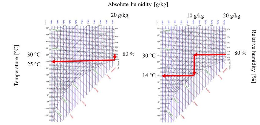
point depression”). As an example, the figure below shows
how adsorption of 50% of an absolute humidity of 20g/kg
leads to a dew point depression from 25°C to 14°C.
Figure 11: Dew point depression through adsorption (illustrative)H U MI DI T Y CONT ROL FOR H V BAT T E RY SYST E MS MANN+ H U MM E L 11
3.2.3 Product design
To calculate the required amount of adsorbent, the environ-
mental conditions the HV battery system is exposed to must
be known. Operation in hot, humid climates will pose the
greatest challenge as the air entering the HV battery system
will carry more water vapor, thus increasing the absolute
humidity inside the system.
As efficient battery cooling is also required especially
under these conditions, the risk of water condensation is
especially high. With battery operating temperature Top and
the typical ambient temperature Tam and the free air volume
in the battery housing Vbatt, the volume of air Vin flowing into Figure 12: Köppen-Geiger Map13
the battery is
Vin = 0,5 * Vbatt * (Top – Tam) / (Top + Tam) Vin = 0.5 · Vbatt · (Top – Tam) / (Top + Tam) (5)
The amount of water vapor mwater entering with the air is
mwater = Vin * η(Tam)(6)
η(Tam) is the amount of water vapor per m³ at tempera-
ture Tam when saturated.
Water load [wt-%]
Tam strongly depends on the local climate where the car is
operated. Using a value for Tam where vapor inflow is at a
maximum results in a maximum water mass to be adsorbed,
thus defining the required amount of adsorbent. In addition,
depression [°C]
Dew point
the load-dependent water capacity has to be considered.
The achievable dew point depression decreases with
increased loading.
After the full adsorption capacity is reached, the part has
to be replaced. As the adsorbent will capture moisture, the
product is sealed inside the package to maintain the full Figure 13: Dew point depression as function of water load
capacity prior to assembly.
Figure 14: Air Dryer Cartridge.12 M A N N +HUMME L HUMIDITY CONTROL FOR H V BAT T E RY SYST E MS
References
1 U NFCCC, Paris Agreement (2015), http://unfccc.int/files/essential_background/convention/application/pdf/english_paris_agreement.pdf,
accessed on 2017-06-19
2 UNFCCC, Paris Declaration on Electro-Mobility and Climate Change & Call to Action (2015),
http://newsroom.unfccc.int/media/521376/paris-electro-mobility-declaration.pdf, accessed on 2017-06-19
3 Roland Berger – Automotive Competence Center, Forschungsgesellschaft Kraftfahrwesen mbH Aachen, E-mobility Index Q2 2017 (2017),
accessed on 2017-06-19
4 Nykvist, B., Nilsson, M., Rapidly falling cost of battery packs for electric vehicles, Nature Climate Change, ISSN 1758-678X, 5(2015), 329–332,
http://dx.doi.org/10.1038/NCLIMATE2564
5 Manager Magazin online, Interview with Thomas Sedran, 21.10.2016,
http://www.manager-magazin.de/unternehmen/autoindustrie/interview-volkswagen-konzernstratege-sedran-zu-elektroauto-offensive-a-1117222.html,
accessed on 2017-06-19
6 Bloomberg New Energy Finance, Electric vehicles to be 35% of global new car sales by 2040 (2016),
https://about.bnef.com/press-releases/electric-vehicles-to-be-35-of-global-new-car-sales-by-2040, accessed on 2017-06-19
7 Thielmann, A., Sauer, A., Wietschel, M., Gesamt-Roadmap Lithium-Ionen-Batterien 2030 (2015)
http://www.isi.fraunhofer.de/isi-wAssets/docs/t/de/publikationen/GRM-LIB.pdf, accessed on 2017-06-19
8 Bruning, A., Why Li-ion batteries catch fire, Chemical & Engineering News, ISSN 1520-605X, 92(2016), 33,
http://cen.acs.org/articles/94/i45/Periodic-graphics-Li-ion-batteries.html, accessed on 2017-06-19
9 Reid, G., Julve, J., Second Life-Batteries as flexible storage for renewable energies, 2016,
http://www.bee-ev.de/fileadmin/Publikationen/Studien/201604_Second_Life-Batterien_als_flexible_Speicher.pdf, accessed on 2017-06-19
10 Golubkov, A.W., Fuchs, D., Wagner, J., Wiltsche, H., Stangl, D., Fauler, G., Voitic, G., Thalera, A., Hacker, V., Thermal-runaway experiments on consumer
Li-ion batteries with metal-oxide and olivin-type cathodes, RSC Advances, ISSN 2046-2069, 4(2014), 3633-3642
11 Golubkov, A.W., Scheikl, S., Planteu, R., Voitic, G., Wiltsche, H., Stangl, C,, Fauler, G., Thalera, A., Hacker, V., Thermal runaway of commercial 18650 Li-ion
batteries with LFP and NCA cathodes – impact of state of charge and overcharge, RSC Advances, ISSN 2046-2069, 5(2015), 57171-57186
12 Available e.g. from http://www.dolder-ing.ch/wissen/Lueftung-Klima/h-x-diagramm/Mollier_h-x-diagramm_Bild.htm
13 Available e.g. from http://koeppen-geiger.vu-wien.ac.at/
Authors
Dr. Michael Harenbrock finished his Ph.D. thesis on Organic Chemistry in 1994. After joining MANN+HUMMEL GMBH in 1998, he managed the Materials
Development Department for filters. Since 2013, he is responsible for company´s strategy towards Electric Mobility and Fuel Cells. He represents
MANN+HUMMEL in several clusters and industry organizations. His current position is Business Development Manager E-Mobility.
Corresponding author: MANN+HUMMEL GMBH, Schwieberdinger Str. 126,71636 Ludwigsburg, Germany, michael.harenbrock@mann-hummel.com
Dr. Stefan Kunze studied physics in Tübingen and Toronto. He finished his Ph.D. thesis on astrophysical applications of numerical methods in 2000. After
joining MANN+HUMMEL in 2008, he was working as a CFD Engineer in the thermodynamics group in Advanced Engineering. His current position is Simu-
lation Expert CFD and FEA, and Expert Algorithms for IoT in advanced development.
Stephan Niemeyer studied Process Engineering at the Hochschule Mannheim. He has been working with MANN+HUMMEL since 1999 as a development
engineer responsible for development and testing of adsorptive air dryers for pneumatic systems on commercial vehicle applications and battery housings.You can also read