Development of a Localization System Based on VLC Technique for an Indoor Environment
←
→
Page content transcription
If your browser does not render page correctly, please read the page content below
J Electr Eng Technol Vol. 10, No. ?: 742-?, 2015                                                                    ISSN(Print) 1975-0102
http://dx.doi.org/10.5370/JEET.2015.10.1.742                                                                        ISSN(Online) 2093-7423

    Development of a Localization System Based on VLC Technique for an
                            Indoor Environment

                              Keon Young Yi*, Dae Young Kim† and Kwang Moo Yi**

            Abstract – In this paper, we develop an indoor localization device which embeds localization
            information into indoor light-emitting-diodes (LED) lighting systems. The key idea of our device is the
            use of the newly proposed “bit stuffing method”. Through the use of stuff bits, our device is able to
            measure signal strengths even in transient states, which prohibits interference between lighting signals.
            The stuff bits also scatter the parts of the signal where the LED is turned on, thus provides quality
            indoor lighting. Additionally, for the indoor localization system based on RSSI and TDM to be
            practical, we propose methods for the control of LED lamps and compensation of received signals. The
            effectiveness of the proposed scheme is validated through experiments with a low-cost implementation
            including an indoor navigation task.

            Keywords: ID stuffing, Indoor localization, LED lighting, RSSI measurement, Stuff bits, TDM

                        1. Introduction                                      receivers, precise delay control, and sensitivity to the phase
                                                                             noise [8], [11]. These in turn bring cost and complexity
   Indoor lighting using white LEDs has drawn much                           problems when implementing the actual system. RSSI-
attention due to its energy efficiency [1]. Also, due to the                 based localization systems using RF carrier[12], dual-tone
advantage of LEDs being able to operate in high                              multi-frequency [13], time allocation [14], RSSR [11] and
frequencies, communication using visible light (VLC) with                    wavelength allocation [15] have been reported in the
these LEDs has drawn much interest as well [1-4]. Over                       literature. Although RF carrier and dual-tone multi-
the past few decades, many indoor localization systems                       frequency techniques have very good estimation accuracy,
(ILSs) based on IR, Ultrasound, RFID, WLAN, Bluetooth,                       they have limitations. RF carrier technique requires
and UWB have been proposed, but these systems have                           additional compensation since frequency response of Tx
limitations such as the necessity of additional infrastruc-                  and Rx is unstable depending on the frequency. Dual-tone
ture, low accuracy, noises, electromagnetic interference,                    multi-frequency technique needs to consider signal-to-
multi-path effects, low security, and etc [5, 6]. Naturally,                 noise ratio (SNR) for the actual system to work, since the
much research has been conducted recently on using these                     SNR and the positioning error are inversely proportional.
indoor LED lighting and VLC techniques as an alternative                     Additionally, these techniques based on the frequency
indoor localization signal for places where satellite global-                modulation require a high-speed analog-to-digital converter
positioning-system (GPS) signals are not available [6-15].                   (ADC), a broadband low-noise amplifier (LNA), and more
The biggest advantage of using VLC techniques for indoor                     computing power, thus increasing the cost of the system
localization is that no additional infrastructure is required                and the overall complexity. In case of time allocation and
for the installation since the system uses existing infra-                   RSSR techniques based on time division multiplexing
structure of LED ceiling lamps, which reduces the cost of                    (TDM), their drawback is the necessity of synchronization
the ILS.                                                                     process [6]. In addition, the maximum number of LED
   For VLC-based ILSs, to acquire the position of an object,                 lamps could be limited in TDM method to prevent LED
positioning techniques based on angle of arrival (AoA),                      flickering. Wavelength allocation technique requires
time of arrival (ToA), time difference of arrival (TDoA),                    additional devices such as an optical filter, multiple Rx [6].
and received signal strength indication (RSSI) are widely                       Here, we focus on RSSI and TDM based localization
used [7, 8]. AOA [9], ToA, TDoA [7, 10] approaches have                      technique for VLC-based ILS due to the fact that they do
disadvantage such as deployment of an array of image                         not require precise delay control, additional device, and
sensors, synchronization problem of all transmitters and                     high-performance hardware. For this type of method,
                                                                             identifications (IDs) are embedded to each LED lamp
†   Corresponding Author: Dept. of Electrical Engineering, Kwangwoon
    Univesrity, Korea.(akmasky@gmail.com)                                    control signal during a given time slot, and the way they
*   Dept. of Electrical Engineering, Kwangwoon University, Korea.            are embedded is critical for the accuracy of localization
    ( keonyi@kw.ac.kr)                                                       and the quality of lighting. The embedding should be done
** Computer vision laboratory in Ecole Polytechnique Fédérale de
    Lausanne. ( kwang.m.yi@gmail.com)                                        such that IDs are easily retrievable and have minimal
Received: September 5, 2014; Accepted: November 20, 2014                     impact on human visible light perception (i.e., having a

                                                                       742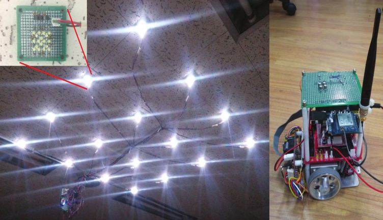
Keon Young Yi, Dae Young Kim and Kwang Moo Yi
repetitive signal of over 50 Hz to reduce eye fatigue). Also,
the length of the pulse for ID needs to be kept at minimum
in order to maximize the time duration of the LED being
on, which prevents LED flickering. However, as the
number of LED lamps increase, more bits are required to
embed ID. This in turn means more bits require shorter
pulse intervals, which brings cost problems when choosing
devices for implementation.
Another problem when implementing the RSSI-TDM
method is interference between ID pulses. The interference
Fig. 1. Indoor localization system with LED lamps and
make it difficult to measure the RSSI value accurately optical receiver mounted on the robot.
because the previous lamp state (ID pulse on or off) affects
the RSSI value of the receiver. Moreover, in real world lamp’s IDs are encoded as rows and columns to reduce
scenarios, the RSSI value at the receiver is affected by the the number of bits in representation. In short, the 50 Hz
environment such as ambient light, roughness of the floor, repetitive lamp driving signal is composed of the
measurement error, and so on, unlike simulation. illuminating interval (which is always 1), the 12-bit signal
In this paper, we propose a new method for embedding interval (START_BIT:010, ID_BIT:CcccRrrr, END_BIT:0).
IDs into LED lighting using the newly proposed “ID The signal interval is referred to as the VLC_Packet. In
stuffing” to avoid lighting flickering and to prevent inter- case of the lamp located at column 1 row 1, the ID_BIT
pulse interference. In addition, we present a column-row and VLC_Packet will be [10001000] and [010100010000]
lamps driving method, which minimizes the off-state of the respectively, whereas in case of column 3 row 2,
lamp and interference between adjacent lamps. To do so, [00100100] and [010001001000].
the proposed method activates only one column or row The receiver uses a low-cost photo-diode (SFH-213)
lamps at a given time slot when sending the VLC_Packet. to measure the strength of the light source in the visible
Additionally, for RSSI/TDM-based ILS to be more light spectrum. The half angle of photo-diode is ±10
practical, we embed the compensation functionality for the degree and the radiant sensitive area is 1 mm2. As the
ambient light and the roughness of the floor. Compared START_BIT is detected in the receiver, the receiver
to other VLC-based ILSs, our system has the following decodes the following ID_BIT and measures the signal
advantages; Simplicity of the implementation, low-cost, strength. In this manner, the receiver is able to recognize
auto-synchronization of the receiver, scalability for a a start point of VLC_Packet. Thus the proposed system
number of LED lamps, and good accuracy in real world does not require synchronization between the transmitters
scenarios. and the receiver. When decoding, if the pulse width is
To demonstrate the effectiveness of the proposed system, large, it is easy to obtain the signal strength, but the
we implement an indoor localization system using LED overall signal interval becomes long, thus resulting in less
lamps and a mobile robot equipped with an optical receiver. illuminating interval and poor lighting. This is because, in
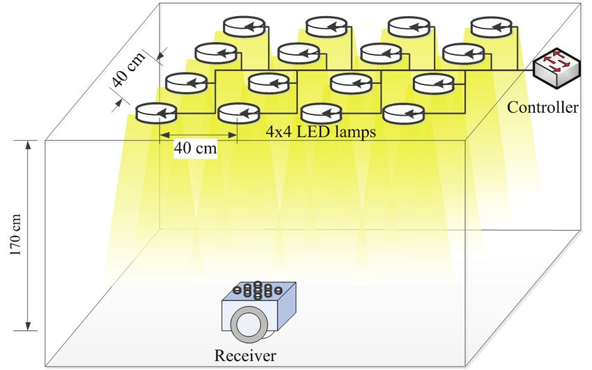
The LED lighting system is configured as a 4 × 4 grid the VLC_Packet, at least nine of the pulses are ‘0’, and
with light sources placed 40 cm apart from each other on therefore provides poor lighting in the signal interval.
the ceiling. The receiver mounted on the robot is located Conversely, if the pulse width is short, then the illuminating
on the floor (170 cm from the ceiling). With this system interval becomes long, providing good lighting, but
configuration, we have the indoor localization result of measuring the strength of the light coming from each lamp
position error less than 3 cm. In addition, we show that the becomes hard. Our core contribution is the signal encoding
mobile robot can move autonomously using the proposed method which overcomes this trade-off. We use short pulse
method. intervals but insert small pieces of illuminating intervals
between each pulse in the ID_BIT, which we call “ID
stuffing” (borrowing the concept of bit stuffing from the
2. System Description Control Area Network Protocol [16]). This insertion of
stuff bits acts as if we scatter our ID signal interval onto the
As shown in Fig. 1, our indoor localization system entire driving signal, which has an important effect. This
consists of 16 LED lamps configured as 4 × 4 grids placed scattering separates ID signal bits and keeps them from
40 cm apart from each other on the ceiling, and a low-cost interfering with each other, allowing shorter pulse intervals.
receiver located on the floor (170 cm from the ceiling).
Each lamp is fabricated with 18 white LEDs to ensure an
illuminance level of 60 lux. The viewing angle of LED 3. Measuring RSSI
(NBL-R3W) is 30 degree and the typical luminous
intensity is 5.0 cd. The 16 lamps are controlled by a single To show that a simple straightforward implementation
8-bit microcontroller ATmega128 (Atmel Co.), and the without stuff bits is not feasible, we experimented with two
743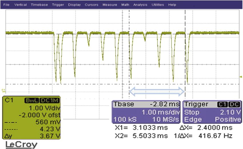
Development of a Localization System Based on VLC Technique for an Indoor Environment

                                                                       2nd column lamps (thick line) are placed. To get the
                                                                       distance from the RSSI, we have to use the right hand side
                                                                       figure, re-plotting the data according to distances. However,
                                                                       as we can see in the case of 2nd column lamps (Fig. 3:
                                                                       right), it is not feasible to get the distance from the RSSI
                                                                       because the displacements of the receiver from the peak
                                                                       point are not symmetric, that is, the RSSI changes in right
                                                                       hand side of the peak and the changes of the other side are
Fig. 2. Measured signal strength of lights to driving pulse
                                                                       different (left hand side signal is strong). This phenomenon
        width of 700 us (left) and 100 us (right).
                                                                       results from the interference of the previous ID pulse.
pulse widths, 700 us and 100 us. We will also show how
                                                                       3.2 RSSI with ID stuffing
the stuff bits work even though we choose short pulse
width.                                                                    To prevent the interference of the previous ID pulse, we
                                                                       employed bit stuffing method between ID pulses.
3.1 RSSI without ID stuffing                                              In Fig. 4, stuff bits of duration 500 us (red dashed line)
                                                                       are inserted just before the row id pulses of duration 100 us,
   In Fig. 2, with pulse interval of 700 us, the strength of           which results in a longer VLC_Packet without losing the
each row and column LED lamps can be easily measure                    illumination interval (illumination interval is scattered
by observing their strengths at their steady state. RSSI               inside the signal interval). Unlike the results of the straight-
values of each column lamps are 0.35, 3.80, 1.40, and 0.20             forward approach in Fig. 2 and Fig. 3, using stuff bits gives
volts, respectively. However, using 700 us gives poor                  accurate measurements as shown in Fig. 5.
illumination, since the VLC_Packet is too long (9 zeros                   The measured RSSI values for each row lamps, under
take out 6,300 us of the 20,000 us, i.e., only 68.5% being             peak values of the arrow marked interval, are 0.95, 3.75,
the illuminating interval). In case of using pulse interval of         1.85, and 0.70 volts, respectively. The measurement results
100 us, the signals do not reach their steady states and are           for the receiver position changes are similar to Fig. 3 but
in transient states even at the end of each pulse intervals.           with symmetric results. Thus we can have unique RSSI
Thus, we used these final transient values to obtain the               for a given distance as shown in right hand side figure.
RSSI, the values of each column lamps are 0.35, 3.25, 1.55,            This allows accurate estimation of the distance from the
and 0.35 volts, respectively. However, the quality of the
measured RSSI is poor in this case.
   To figure out the relation between the receiver location
and RSSI of the lamp, we measured RSSI of each column
and row lamps while the receiver location varies from 0 to
120 cm along the perpendicular direction of the column
and row lamps.
   We only present the characteristic curves of the column
lamps (Fig. 3: left) because the row lamps showed almost
same characteristics. From these curves, it is possible to
obtain the characteristic curves between the receiver                  Fig. 4. LED lamps driving signal with 9 stuff bits (Column-
location and the RSSI as shown in Fig. 3 (We only denoted                      1 and Row-1 turn on).
the 2nd column lamps case at right hand side, and we
named it RSSI curve of the 2nd column lamps.).
   In Fig. 3(left), the measured results of RSSI with pulse
interval of 100 us, we can see a peak at 40 cm where the

Fig. 3. Relation between receiver location and RSSI of the             Fig. 5. Measured signal strength of the lamps with stuff
        column lamps.                                                          bits.

                                                                 744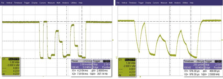
Keon Young Yi, Dae Young Kim and Kwang Moo Yi

                                                                               established

                                                                        STEP 2: Normalize the compensated signal
                                                                        n_rssi = (c_rssi - c_min) * 1000 / (c_max - c_min) (2)
                                                                        c_rssi: compensated value in step 1
                                                                        c_min: minimum RSSI value of c_rssi for the END_BIT
                                                                                interval
                                                                        c_max: the signal average value of c_rssi for the stuff
Fig. 6. Relation between receiver location and RSSI of 2nd
                                                                                pulse interval
         column lamps after normalization.

measured signal strength.
   However, the characteristic curve shown in Fig. 6 varies                           4. Indoor Localization
depending on the location of the receiver or ambient
lighting. Specifically, the signal shown in Fig. 5 is shifted           After the RSSI measurement, we convert the
up without changing shape in daytime, whereas it shifted              measurement to the distance between the receiver and
down in nighttime. This effect could be minimized with                column or row lamps. For this conversion, we need a
simple addition since we know the RSSI value of the                   function representing the RSSI curves shown in Fig. 7.
END_BIT interval where all LEDs are turned off, when the              Here we state how to obtain the function, and in turn, the
characteristic curve was established. We also have to                 location of the receiver from the measured signals.
compensate RSSI curve, because the illuminance of the
floor is not even everywhere. Simple experiment reveals               4.1 RSSI function
this problem as shown in Fig. 7.
   In Fig. 7, the receiver location varies from 0 to 120 cm              According to the light diffusion equation [17], this
along perpendicular direction of 1st row lamps (red line)             relationship can be approximated as follows:
and the center of two row lamps (blue line). It is obvious
that we have to use different RSSI curve to get more exact                                l = a1e − b1s + a2 e − b2 s          (3)
location. However we cannot decide which RSSI curve is
fit for the current measure because the receiver location is          where l is the distance between the light sources s and
unknown. Thus we employed normalization technique to                  the receiver and s is the signal strength measure. Here,
get the unified RSSI curve that is the average curve of               we have two exponential terms since we have multiple
shown in Fig. 7 (right), even though averaging errors exist.          lamps contributing to the measurements (one row or
   The normalization of the signal is performed with the              column at each time). The number of exponential term
maximum value and the minimum value of the signal                     should be equal to the number of lamps contributing to the
measured. The maximum value is obtained by averaging                  measurement, but we found experimentally that two was
the value of illuminating or stuff pulse intervals, and the           sufficient. In our experimental setup, a1=1112, b1 = 0.0341,
minimum value is set with the negative peak value in                  a2 = 175.6, b2 = -4.1E-05.
STOP_BIT interval. The detailed normalization process is
as follows:                                                           4.2 Measuring receiver location

  STEP 1: Compensate ambient lighting                                    To obtain the receiver location using the RSSI function,
                                                                      since we use the projected displacement along the ground
  c_rssi = m_rssi + (s_min - m_min)                (1)                plane instead of the distance between the lamps and the
  m_rssi: measured signal strength                                    receiver, we have to use the following trigonometry
  m_min: minimum RSSI value of the END_BIT interval                   relation.
  s_min: the value of m_min when the RSSI curve
                                                                                   ri =   li2 − 1702 ,        i = 1, 2,3, 4    (4)

                                                                      where 170 is the vertical distance between the lamps and
                                                                      the ground plane, l is the distance between the lamps and
                                                                      the receiver, and r is the projected displacement from the
                                                                      column(or row) lamps and the receiver.
                                                                         Only three projected displacements are chosen for
                                                                      calculating the distance d because the slope of the RSSI
Fig. 7. RSSI curve of 2nd column lamps for different                  curve shown in Fig. 7 is steep where the signal is weak. In
        locations.                                                    other words, the weakest signal has low signal-to-noise

                                                                745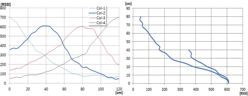
Development of a Localization System Based on VLC Technique for an Indoor Environment
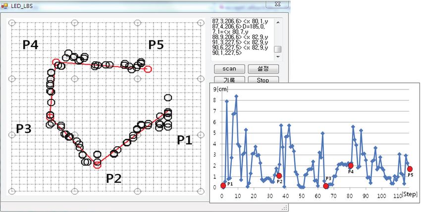
Fig. 9. Indoor localization system with LED lighting
Fig. 8. Selection method of the displacement d.
ratio, and adding it only harms the overall estimation.
Consequently, we can obtain the position of the receiver
with this three selected displacements using the following
equation.
s1 + sgn ( s3 − s1 ) s2 − s3
d = 40n + (5)
3
where si indicates the selected displacement. For instance, Fig. 10. Distribution of the localization error
if r1 is the projected displacement of the weakest signal
among them, we set r2, r3, and r4 to s1, s2, and s3, we implemented the 4 × 4 LED lighting and an optical
respectively. The ‘n’, the number of starting column receiver on the micro-mouse as shown in Fig. 9. In order to
lightings chosen, serves to add the offset to the strongest check the position of the receiver, the orthogonal projection
lightings from the origin. As we can see in Fig. 8, it is of the position of LEDs onto the ground plane was marked
obvious that we have to add two times of the lighting on the floor.
layout span, 40 cm, to the average of the selected We conducted two kinds of experiments. Firstly, we
displacements, the 2nd term of the right hand side (5). If r4 checked the performance of the localization capability. We
is discarded when the receiver locates near 2nd LED lamps, manually placed the receiver on a 10 cm grid and evaluated
only one lighting layout span should be added. the localization error at each grid point. We then performed
As a special case, the receiver located near the edge of navigation control of the mobile robot with the position
the lighting area, any side of the Fig. 8, only two distances data measured by the receiver.
are available if the others are exceeded their limits too As we can see in Fig. 10, the error, Euclidean norm of
much because their signal strengths are weak. For these the error of each axis, remains under 3 cm. Although the
cases, the position of the receiver is obtained by the manual localization of the receiver may contain some error
following equation. since we located the receiver by hand, we can say that the
performance of the proposed system is reasonably accurate
s1 − s2 for the indoor localization comparing the results in [11],
d = m+ (6)
2 the maximum and mean values of location errors were 3.89
cm and 1.68 cm, respectively in simulation, whereas, in
experiments, they had the error of 10.29 cm and 3.24 cm.
For the navigation, we developed a program (Fig. 11, we
The position of the receiver from row lamps is obtained call it host after this) that can communicate with the mobile
by the same approach, which gives us 2D location of the robot (micro-mouse built with stepping motors) via
receiver on the ground plane. network. The grid of the screen is set by 5 cm, and the 16
circles denote the projection of LEDs. The five red circles
4.3 Indoor location example shown in the figure are the target points which the robot
has to move through.
To demonstrate the usefulness of the proposed method, The receiver was mounted on the mobile robot to
746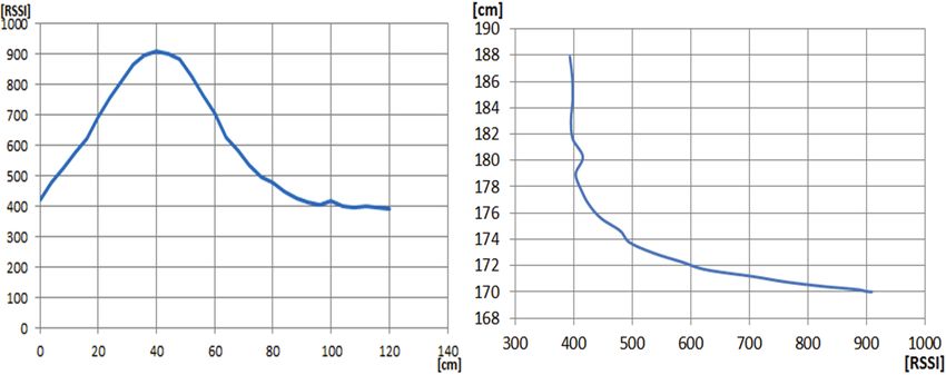
Keon Young Yi, Dae Young Kim and Kwang Moo Yi

                                                                                           Acknowledgements

                                                                          This work was supported by a research year grant 2012
                                                                       at the Kwangwoon University.

                                                                                                References

                                                                       [1]    D. O’brien, L. Zeng, H. Le-Minh, G. Faulkner, J. W.
                                                                              Walewski, and S. Randel, “Visible Light Communi-
         Fig. 11. Example of the indoor navigation                            cations: challenges and possibilities,” Personal, Indoor
                                                                              and Mobile Radio Communications, 2008. IEEE 19th
measure the location as shown in Fig. 9(right). The                           International Symposium on, pp. 1-5, Canes, 15-18
orientation of the robot was estimated in the host computer                   Sept. 2008.
based on the changes of the robot location, since the                  [2]    T. Komine and M. Nakagawa, “Fundamental analysis
proposed localization system can only measure the position                    for visible-light communication system using LED
of the robot. The initial orientation of the robot was                        lights,” Consumer Electronics, IEEE Transactions on,
calculated by moving the robot 5 cm backwards, which is a                     vol. 50, no. 1, pp. 100-107, 2004.
bit longer than the precision of the receiver, and then the            [3]    H. Le-Minh, D. O’brien, G. Faulkner, L. Zeng, K.
robot was moved forward to the origin P1. Then, the host                      Lee, D. Jung, Y. Oh, and E. T. Won, “100-Mb/s NRZ
initiated the rotation command to correct the heading of the                  visible light communications using a postequalized
robot and the move command to step forward. In this                           white LED,” Photonics Technology Letters, IEEE,
manner, robot passed through the target points marked on                      vol. 21, no. 15, pp. 1063-1065, 2009.
the screen. The trajectories of the robot are marked with              [4]    H. Le Minh, D. O'Brien, G. Faulkner, L. Zeng, K. Lee,
dark circles around straight lines connecting 5 target points.                D. Jung, and Y. Oh, “High-Speed Visible Light Com-
   The position error (Fig. 11: right, small dots stand for                   munications Using Multiple-Resonant Equalization,”
error at the target points P1-P5) did not exceed 9 cm, which                  Photonics Technology Letters, IEEE, vol. 20, no. 14,
is different from the measured error of the first experiment.                 pp. 1243-1245, 2008.
The major reason cause of difference is the changes of                 [5]    Y. Gu, A. Lo, and I. Niemegeers, “A survey of indoor
the receiving angle of the light, which comes from the                        positioning systems for wireless personal networks,”
vibration of the robot on the uneven floor. However the                       Communications Surveys & Tutorials, IEEE, vol. 11,
robot completed its mission with the error less than 3 cm.                    no. 1, pp. 13-32, 2009.
   Currently, we are conducting a follow-up study on                   [6]    S.-H. Yang, E.-M. Jung, and S.-K. Han, “Indoor
recognizing the direction and compensating the inclination                    Location Estimation Based on LED Visible Light
of the receiver to make the proposed system more reliable.                    Communication Using Multiple Optical Receivers,”
                                                                              Communications Letters, IEEE, vol. 17, no. 9, pp.
                                                                              1834-1837, 2013.
                      5. Conclusion                                    [7]    S.-Y. Jung, S. Hann, and C.-S. Park, “TDOA-based
                                                                              optical wireless indoor localization using LED ceiling
   We have developed an indoor localization device that                       lamps,” Consumer Electronics, IEEE Transactions on,
embeds localization information into an indoor LED                            vol. 57, no. 4, pp. 1592-1597, 2011.
lighting system. The key idea of our scheme was to use                 [8]    T.-H. Do and M. Yoo, “TDOA-based indoor posi-
“bit stuffing method.” Using stuff bits, our method was                       tioning using visible light,” Photon Netw Commun,
able to measure signal strengths independent of the                           vol. 27, no. 2, pp. 80-88, Aug. 2014.
previous signal. This allowed our implementation to use                [9]    S. Haruyama, M. Nakagawa, and M. Yoshino, “High-
a simple function to measure the location of the receiver.                    accuracy Positioning System using Visible LED
The stuff bits also scattered the parts in the signal where                   Lights and Image Sensor,” Radio and Wireless Sym-
the LED was turned on, enabling our scheme to provides                        posium, IEEE, pp. 439-442, Orlando, 22-24 Jan. 2008.
quality indoor lighting as well, which was under-                      [10]   K. Panta and J. Armstrong, “Indoor localisation using
considered in previous works. The proposed bit stuffing                       white LEDs,” Electronics Letters, vol. 48, no. 4, p.
method would be useful for RSSI/TDM-based indoor                              228, 2012.
localization applications. The effectiveness of the proposed           [11]   S.-Y. Jung and C.-S. Park, “Lighting LEDs based
scheme was validated through experiments with an actual                       Indoor Positioning System using Received Signal
low-cost implementation and navigation example, showing                       Strength Ratio,” Proceedings of 3DSA2013, vol. 8, p.
promising results.                                                            5, Osaka, 26-28 June 2013.

                                                                 747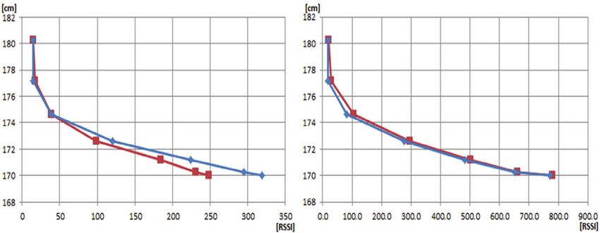
Development of a Localization System Based on VLC Technique for an Indoor Environment

[12] H.-S. Kim, D.-R. Kim, S.-H. Yang, Y.-H. Son, and S.-                                 Kwang Moo Yi He received his B.S.
     K. Han, “An Indoor Visible Light Communication                                       and Ph.D. degrees from the Depart-
     Positioning System Using a RF Carrier Allocation                                     ment of Electrical Eng. and Computer
     Technique,” Lightwave Technology, Journal of, vol.                                   Science of Seoul National Univ., Seoul,
     31, no. 1, pp. 134-144, 2013.                                                        Korea, in 2007 and 2014, respectively.
[13] P. Luo, M. Zhang, X. Zhang, G. Cai, D. Han, and Q.                                   Currently, he is a post-doctoral re-
     Li, “An indoor visible light communication position-                                 searcher in the computer vision labora-
     ing system using dual-tone multi-frequency technique,”                               tory in Ecole Polytechnique Fédérale
     Optical Wireless Communications, 2nd International               de Lausanne. His research interests include computer vision,
     Workshop on, pp. 25-29, Newcastle, 21 Oct. 2013.                 visual tracking, augmented reality, motion segmentation,
[14] S.-H. Yang, D.-R. Kim, H.-S. Kim, Y.-H. Son, and                 motion detection, unsupervised Bayesian learning, object
     S.-K. Han, “Visible light based high accuracy indoor             recognition and so on.
     localization using the extinction ratio distributions of
     light signals,” Microwave and Optical Technology
     Letters, vol. 55, no. 6, pp. 1385-1389, 2013.
[15] S.-H. Yang, H.-S. Kim, Y.-H. Son, and S.-K. Han,
     “Reduction of optical interference by wavelength
     filtering in RGB-LED based indoor VLC system,”
     the 16th Opto-Electronics and Communications Con-
     ference, pp. 551-552, Taiwan, 4-8 July 2011.
[16] F. Hartwich, “CAN with flexible data-rate,” 2012.
[17] S. L. Jacques and B. W. Pogue, “Tutorial on diffuse
     light transport,” J. Biomedical Optics, vol. 13, no. 4,
     p. 041302, 2008.

                   Keon Young Yi He received the B.S.,
                   M.S., and PhD. degree in Electrical
                   Eng. from Hanyang Univ. in 1982,
                   1984, and 1993, respectively. He is a
                   Professor in the Dept. of Electrical
                   Eng., Kwangwoon Univ., Korea. His
                   research interests include adaptive
                   control, robotics, real-time system, and
microprocessor applications.

                     Dae Young Kim He received the B.S.
                     degree in Control and Measuring Eng.
                     from Chosun Univ. in 2006, his M.S.
                     degree in Electrical Eng. from Kwang-
                     woon Univ. in 2009. He is a Ph.D.
                     candidate in Electrical Eng., Kwang-
                     woon Univ., currently. His research
                     interests include fuzzy control, LED
lightings, and location based system.

                                                                748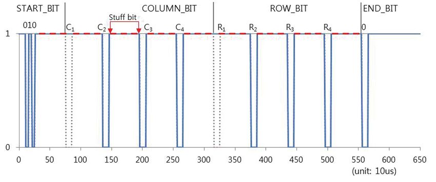

You can also read