A multi-frequency multi-constellation GNSS development platform with an open interface
←
→
Page content transcription
If your browser does not render page correctly, please read the page content below
A multi-frequency multi-constellation GNSS
               development platform with an open interface
    Fabio Garzia, Christian Strobel, Matthias Overbeck, Neelam Kumari, Shrikul Joshi, Frank Förster, Wolfgang Felber
                                                              Fraunhofer IIS, Nuremberg, Germany
                                                              Email:fabio.garzia@iis.fraunhofer.de

       Abstract—This paper presents the GOOSE GNSS open re-                           that the users has to fiddle with several aspects which can be
    ceiver platform. The platform is based on a multi-frequency                       beyond their know-how. This is the case of the TUT-GNSS
    multi-constellation GNSS receiver which can be deployed either                    developed by the Tampere University of Technology using
    as a fixed PC receiver or as an embedded portable one. The
    main feature of this platform is to provide to GNSS software                      an Altera FPGA with the NIOSII soft core [4]. The receiver
    developers the possibility to have a deeper control on receiver                   development was part of the FP7 GRAMMAR project [5].
    hardware and to replace all the provided software functionality                      The approach proposed in this paper has been developed
    with their own software modules. This is possible with the open                   in the GOOSE project. It is meant to be a trade-off between
    interface protocol called Open GNSS Receiver Protocol (OGRP),                     the market black-box receiver model and the academical open
    which has been developed by Fraunhofer in the same project.
    The results show how the receiver hardware performs in the                        one. The idea is that the receiver should offer an open
    different scenarios.                                                              interface which can be directly accessed by the user. In
                                                                                      particular, it should be allowed to run user software on the
                               I. I NTRODUCTION                                       receiver processor. In order to meet the needs of a larger
                                                                                      user base, the receiver supports a fixed Personal Computer
       Nowadays most of portable handheld devices (smartphones,                       (PC) deployment as well as a portable embedded one. Both
    tablets) feature a Global Navigation Satellite System (GNSS)                      scenarios are characterized by different processor capabilities
    receiver and provide a user position. More and more user                          and software requirements. This way users from different
    applications exploit the receiver data to provide the most                        scenarios can make the most of the receiver by this solution.
    heterogeneous type of services. However, the development of                       Additionally, this allows developers who want to start with
    third party software exploiting raw GNSS measurement data                         a PC implementation and move then to an embedded one
    is slowed down by the receiver limitations.                                       to use the same underlying hardware. The paper describes
       Commercial Off-The-Shelf (COTS) receivers are often de-                        the challenges related to the support of different deployment
    fined as black-box receiver, since they provide no accessibility                   scenarios.
    to internal hardware. Typically only the signal to use and the                       The paper is organized as follows. In the first section we
    update rates of the Position, Velocity and Time component                         describe the hardware components of the open receiver system.
    (PVT) solution can be configured. This is the case of state-                       Then we present the OGRP. In the following section we report
    of-the-art receivers like the TR-G3T [1]. A tight coupling                        some experimental results. Finally we draw some conclusions.
    of, e.g., inertial sensor data with the GNSS is possible only
    with the SPAN Receivers from Novatel [2] or with software                                II. O PEN RECEIVER HARDWARE ARCHITECTURE
    receivers. The Novatel SPAN Receivers gives no possibility                           The receiver is composed of an analog-frontend board,
    to run third party software on the processor and they provide                     a baseband board and the processor system. The satellite
    only proprietary protocols for the data exchange between the                      signal received by the antenna is first processed by the analog
    receiver and external modules. The software receivers are very                    frontend. The signal is mixed down to a low Intermediate
    flexible but typically cannot deliver real-time performance.                       Frequency (IF) and then converted to a digital signal by an
       In order to overcome these limitations, open receivers have                    Analog-to-Digital Converter (ADC). The frontend character-
    been developed by the academia. The drawback is that they are                     istics are described in detail in Section II-A. The modular
    often limited to single frequency and single constellation (i.e.                  structure of the system allows users to replace the provided
    GPS). For example, the Namuru Receiver from the University                        frontends with modules of their own, as long as the digital
    of New South Wales adopts the GP2015 Zarlink chip for                             interface is compatible with the baseband board. The digital
    Global Positioning System (GPS) L1 and an Altera Field-                           signal generated by the frontend is processed in the baseband
    Programmable Gate Array (FPGA) with a Nios softcore for                           board. The baseband functionality is implemented partly on
    the digital hardware [3]. The other drawback is that they might                   hardware and partly on software. The hardware part is based
    provide independent tools to get from a satellite signal to the                   on dedicated GNSS modules mapped on a FPGA. This is
    final PVT solution, but a uniform approach is missing, so                          explained in Section II-B. These modules are interfaced with
                                                             978-1-4799-8915-7/16/$31.00
                                                                                         c 2016 IEEE

Authorized licensed use limited to: FhI fur Integrierte Schaltungen Angewandte Elek. Downloaded on February 05,2021 at 09:16:33 UTC from IEEE Xplore. Restrictions apply.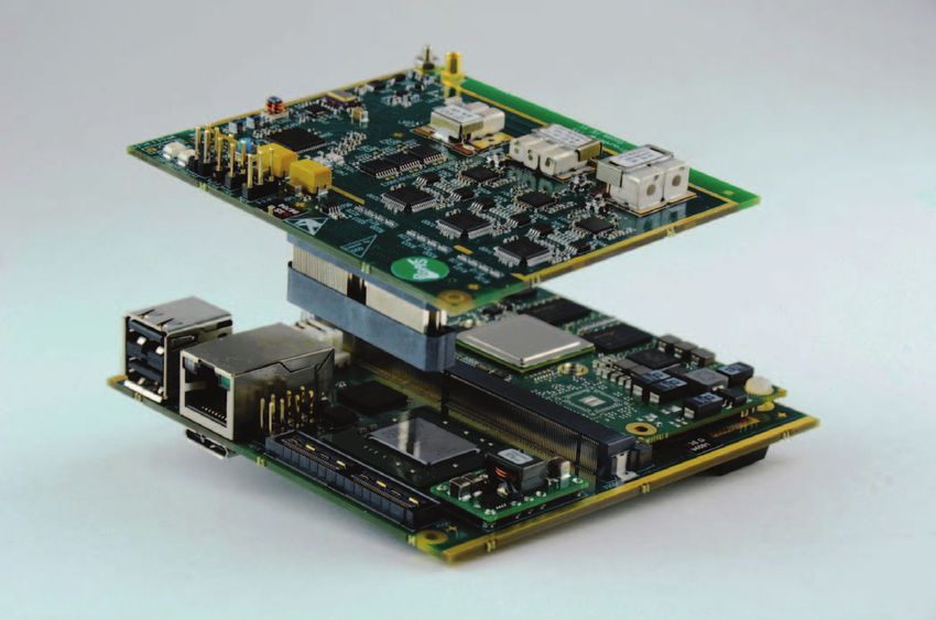
an AXI bus which is controlled by a processor, which runs frequency setting and a ADC. The LO as well as the ADCs
the software tasks. The main feature of the architecture is the have a common reference clock, therefore the channels are
possibility to deploy it in different user scenarios. Therefore synchronous to each other. Only the phase offset between
a special emphasis was given to the interface between the the channels can change every time the device is powered
hardware modules and the software one. This is described in up. After the initialization the phase offset remains constant.
Section II-C. The ADC chosen allows a high linearity of the system with
resolution up to 12 bits, but currently we use only 8 bits. The
A. Frontend board sampling rate of 220 MHz allows a higher resolution of the E5
The modularity of the open receiver allows the possibility AltBOC-Code-Tracking and enables the processing of Orthog-
for the users to develop their own analog frontend with only onal Frequency-Division Multiplexing (OFDM)-signals. The
the requirement being a suitable digital Signal-In-Space (SIS) antenna element (without its own Low Noise Amplifier (LNA)
interface. For the users requiring a complete solution, two and filter) can be directly connected to the RF input of the
separate frontend options, namely the GOOFI board and the frontend
GOOFEX board, are provided. B. Baseband board
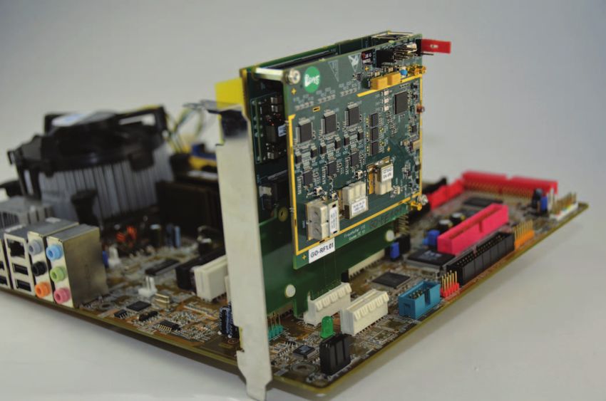
The GOOFI frontend board is depicted on top of Figure 1.
The baseband board is connected to the analog frontend
It is based on three reception channels for separate GNSS
through a Samtec connector (see Figure 1). It is equipped
bands with bandwidths varying between 40 and 68 MHz
with a Xilinx XC7K410T FPGA where a dedicated GNSS
(Figure 2). The first channel supports GPS L1, Galileo E1,
HW subsystem is implemented. The subsystem is depicted in
Russian GLObal NAvigation Satellite System (GLONASS)
Figure 4.
G1 and BeiDou B1, the second one the L2/L2C-band and
GLONASS G2 and the third one E5 AltBOC, E5a, E5b, L5
and B2. These signals are down-converted and digitized by Baseband FPGA
I,Q @ 4Bit, 81MHz clock
the three dual-channel ADCs which run at 81 MSPS sampling 8-to-4 bit I&D Values
selection
rate and 8-bit resolution. The signal gain is controlled through
L1 ADC 8bit
a I2C interface. A dedicated clock generation and distribution output
chip has been designed to coherently derive all the frequencies L2 ADC 3x90
90 AHB DP BRAM
8bit
tracking 2x clk
output Switch
required for the Radio Frequency (RF) Integrated Circuit (IC), channels AHB SLV
L5 ADC 8bit
the ADCs, and the FPGA. The GOOFI frontend is meant to be output Clk_adc Clk_adc Clk_pcie
used with an active antenna, therefore the noise figure depends Coarse
Search
on the antenna used. The DC power supply for the active (FFT Corr)
antenna is controlled by the baseband board.
FFT
RAMS
Clk_acq
131072*4-bit*I,Q AHB APB AHB
APB
AXI
to
AHB/APB bridges
AXI Clk_acq Clk_adc Clk_pcie
AXI Memory-Mapped to PCIe
Endpoint
Fig. 4. FPGA baseband block diagram
The baseband subsystem provides the core functionality
required in a GNSS receiver using dedicated hardware mod-
ules controlled through AMBA/AXI ports. In particular, it
Fig. 1. Single-Board Computer (SBC)-based receiver hardware provides a FFT-based acquisition core and up to 90 channels
for tracking. The acquisition engine supports FFT processing
The GOOFEX frontend (Figure 3) is meant to provide a of up to 16K-point blocks and it is used to correlate the
more flexible solution to cover also future GNSS signals. incoming signal with locally generated PRN replica signals of
It is characterized by a homodyne RF frontend architecture the GPS L1CA or Galileo E1b. Each peak in the correlation
with four independent reception channels, which cover the result indicates the presence of the related satellite signal at
frequency band from 1.0 GHz to 3.5 GHz, depending on the the observed frequency. The position of the peak gives an
antenna and the band selecting filter. Each channel has its information on the code phase. The procedure is replicated
own Local Oscillator (LO), a SPI interface for gain and LO for different frequency values to find out the Doppler of the
Authorized licensed use limited to: FhI fur Integrierte Schaltungen Angewandte Elek. Downloaded on February 05,2021 at 09:16:33 UTC from IEEE Xplore. Restrictions apply.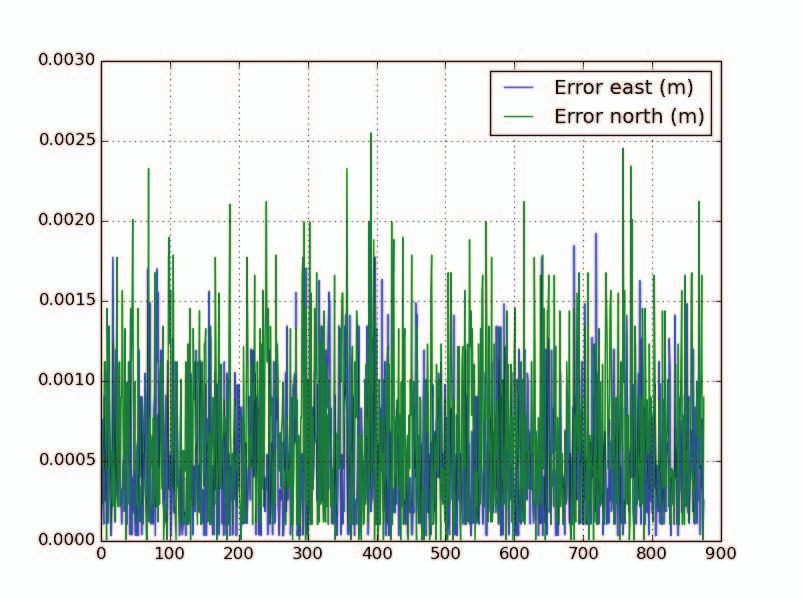
incoming signal and then for each supported satellite to find                      version. The PC interface is typically more flexible and is
    out all present satellites. The Doppler of L2/L5 signal can                       compatible with different PCIe speed selections.
    be estimated from the Doppler of the L1 signal. After a                              The choice of the embedded processor was characterized by
    satellite signal is detected, the user can track it using one                     these two aspects:
    of the provided channels. Each channel is equipped with                              1) the support for a Peripheral Component Interconnect
    5 complex correlators which combine the incoming signal                                 Express (PCIe) interface;
    with delayed versions of the PRN replicas. The result of the                         2) the possibility to get an embedded processor board
    correlations is used in a closed feedback loop to keep the                              which could be easily integrated in a compact and
    signal in tracking. The feedback based on Frequency-Locked                              portable receiver solution.
    Loop (FLL), Delay-Locked Loop (DLL) and Phase-Locked                                 Given these requirements, the choice fell on the Freescale
    Loop (PLL) is implemented in software. A basic version of                         iMX.6 dual-core processor [7], which is equipped with a PCI
    the tracking loops is provided within the system, but the                         Express (Gen 2.0) dual-mode complex core, supporting Root
    users have the possibility to directly access the correlators                     complex and Endpoint operations. The Freescale processor is
    dumps and replace the existing software loops with their own                      provided by several manufacturers in a SBC version based
    customized version. The standard system setup features 90                         on a standard SMARC [8] form factor. The SMARC standard
    channels. However, since the hardware is implemented on                           defines a Printed Circuit Board (PCB) form factor of 82 mm x
    FPGA, the setup can be modified for special user needs. For                        50 mm for extremely compact low-power designs. It foresees
    example, if three instead of five correlator points are used, the                  314 card edge contacts on the PCB of the module which is
    number of channels can be increased.                                              plugged via a low-profile connector on the carrier board with
                                                                                      construction height of 4.3 mm. For the current deployment
    C. Digital Processor Interface                                                    a Kontron SMARC-sAMX6i [9] was chosen as target SBC.
                                                                                      Kontron provides a Linux Linaro Board Support Package
       The modules described above have a generic AXI inter-                          (BSP) to simplify the software development, where the same
    face to allow control from a general-purpose processor. The                       drivers as in the PC version can be used. Figure 1 shows
    processor itself is not integrated on the baseband board.                         the embedded version of the receiver with the SBC plugged
    The target of the project is to allow different deployment                        into the baseband board. In order to allow the interfacing of
    scenarios, which basically means that the baseband board has                      the baseband board with a PC, a PCIe riser card has been
    to support interfacing to a PC, e.g. a desktop variant, as well                   developed to route the signals from the SMARC connector on
    as to an embedded computer system. There are only a few                           the baseband board to a standard PCIe x1 connector of a PC
    standards supported by Xilinx IPs to allow the connection                         motherboard. The target PC Operating System (OS) is Linux
    to a standard desktop PC. Since we need to support high                           Ubuntu. Figure 5 shows the PC version of the open receiver
    data rates (50 Mbps), the choice is limited to high-speed                         plugged into a PC motherboard.
    serial protocols like USB or PCIe. In particular, the PCIe was
    our first choice, since it was already deployed in some of
    our existing systems. On the other hand, the interface to the
    embedded processor provides more freedom. The main design
    choice is whether or not the embedded processor interface
    has to be compliant with the PC one. For example, a parallel
    address/data memory interface could be used to connect with
    an embedded processor, but this would be not suitable for the
    desktop PC version. In such a case the embedded processor
    should be integrated on the baseband board and an additional
    interface should be provided for the desktop PC. This has
    as drawback that the cost of the single baseband board is
    higher because of processor and peripherals cost and it is not
    justifiable for a user which has no interest in the embedded
    version. The alternative is to design two separate version of
    the embedded board, one for the PC and one for the embedded
    processor. This also increases significantly the Non-Recurring                                          Fig. 5. PC-based receiver hardware
    Engineering (NRE) costs and is therefore not an option. That’s
    why the final choice was to make a unique processor interface
    which could be used for both. The processor interface is based                                 III. O PEN GNSS R ECEIVER P ROTOCOL
    on a PCIe core from Xilinx [6]. The PCIe core translates PCIe                        The open GNSS receiver described above is associated to
    commands into memory-mapped transactions for the AXI bus.                         an open receiver protocol called OGRP. The goal of OGRP
    Some core parameters like the link speed and the BAR size                         is to offer a well-defined and self-describing format for the
    have to be set in order to be compatible with the embedded                        available receiver measurements while remaining at the same

Authorized licensed use limited to: FhI fur Integrierte Schaltungen Angewandte Elek. Downloaded on February 05,2021 at 09:16:33 UTC from IEEE Xplore. Restrictions apply.
time vendor neutral. One of the challenges of the protocol
    is to support real-time message exchange between software
    modules as well as logging of the internal receiver status and                                          (a) Autonomous Position Test
    measurements. To fulfill these requirements and to guarantee                                                        Setup
    at the same time a human readable format, JavaScript Object
    Notation (JSON) has been used to implement the protocol.
    This way several libraries based on different programming
    languages can be used to parse the data. The usage of JSON
                                                                                                            GOOSE
                                                                                                                                  PCIe
    simplifies the protocol extension through definition of new                                              Receiver                          PC/SBC
    message types or extension of the defined ones. The open
    GNSS receiver provides already an example implementation
    of GPS L1 and L5 as well as for Galileo E1 and E5a. Further
    signals like GPS L2C and Galileo E5 AltBOC processing are
    currently under development. OGRP is currently available in
    the GitHub Fraunhofer IIS/OGRP branch [10] under a Creative
    Commons license.
       In the GalileoOnline project the support for external loop                                               (b) RTK Position Test Setup
    closure will be provided through the OGRP. New messages to
    specify correlator results (early, present and late correlations)
    and feedback for carrier and code NCOs are currently under                                              GOOSE
    study. These OGRP messages can be exchanged using an inter-                                            Receiver               PCIe
    process communication mechanism with other applications
    running on the same processors. This way it will be possible
                                                                                                            (rover)
    to implement external tracking loops. In particular, in the                                                                              PC/SBC
    GalileoOnline project this feature will be used to implement                                            JAVAD
    vector-tracking loops and Inertial Navigation System (INS)-                                            Receiver               USB
    aided loops.
       Regarding the inter-process communication, ZeroMQ [11]                                               (base)
    has been chosen as software infrastructure. ZeroMQ is a
    distributed-messaging library which provides sockets that
    carry atomic messages using different transport protocols and
    communication patterns. The most common transport proto-                             Fig. 6. Test setups for the evaluation of GOOSE receiver performance
    cols are supported, among the others Transmission Control
    Protocol (TCP), inter-process or in-process. The available
    patterns include request-reply, publisher-subscriber, push-pull.                  evaluation with RTKLIB was made to obtain the Dilution
    ZeroMQ supports different languages and operating systems.                        of Precision (DoP), in particular the Geometry Dilution of
                                                                                      Precision (GDoP) and Position Dilution of Precision (PDoP).
                                  IV. R ESULTS                                        The PDoP gives information about the impact of the satellite
       The GOOSE platform has been tested in a laboratory                             constellation on the position quality. To take account to differ-
    connected to a roof antenna receiving a real GNSS signal                          ent satellite constellations, several automatic tests have been
    from satellites. Several basic tracking tests with GPS L1 and                     performed with PC and embedded version (SBC). Table I show
    L5 as well as Galileo E1b and E5a have been performed                             the evaluated standard deviation (1 sigma) and the maximum
    to check the correct reception of these signals. A series of                      error against the known position of the roof antenna for four
    measurements have been conducted using only GPS L1 to                             different measurements, two with the PC and two with the
    evaluate the autonomous position performance and the Real                         SBC platform. The values of RTKLIB are in brackets. The
    Time Kinematic (RTK) performance with a zero baseline setup                       position accuracy of the internal PVT and RTKLIB are similar
    (see Figure 6). For these performance tests the receiver own                      and varies between approx 5.20 m and 12.95 m in the different
    software developed by Fraunhofer IIS and the RTKLIB [12]                          tests. The precision is about 1.77 to 3.38 m. The main reason
    have been employed. The RTKLIB has been modified to                                for the low accuracy could be that the carrier-assisted DLL
    support OGRP.                                                                     is not enabled in the current implementation of the receiver
                                                                                      software. In a carrier-assisted DLL approach the code NCO
    A. Autonomous position performance tests                                          is mainly controlled by the output of the PLL, which is less
      To test the autonomous position performance of GOOSE,                           noisy than the DLL. The DLL output is only used with a
    the receiver has been connected to a roof antenna as depicted                     low bandwidth (approx. 0.1 Hz) to compensate the offset
    in Figure 6 (a)). The data of the internal PVT of the re-                         between carrier and code Doppler. This method reduces the
    ceiver application are logged and evaluated. Additionally an                      noise on the code phase measurement and therefore on the

Authorized licensed use limited to: FhI fur Integrierte Schaltungen Angewandte Elek. Downloaded on February 05,2021 at 09:16:33 UTC from IEEE Xplore. Restrictions apply.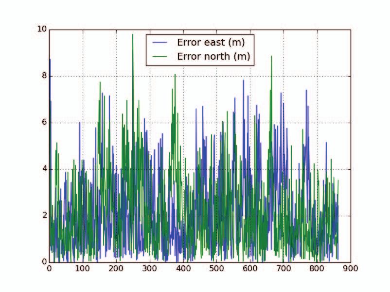
Fig. 7. Position error in East-North with PC platform (Autonomous position        Fig. 9. Position in East-North with PC and SBC platforms (Autonomous
    test 1)                                                                           position test 1 and 3)

    Fig. 8. Position error in East-North with SBC platform (Autonomous position       Fig. 10. Position error in East-North with PC platform (RTK position test 5)
    test 3)

                                                                                      tests have been performed. An extracts of the measurements
    position calculation. It was not employed because it led to
                                                                                      are shown in Table II. Figures 10 and 11 show the errors
    artifacts in the pseudoranges due to an insufficient code NCO
                                                                                      over time for two of the measurements made respectively with
    resolution. If this problem is solved, a higher autonomous
                                                                                      the PC platform and the SBC platform. Figure 12 shows a
    position accuracy could be reached.
                                                                                      comparison of the East-North position calculated with the PC
       Figures 7 and 8 show the errors over time for one of the
                                                                                      platform and the SBC platform.
    measurements made respectively with the PC platform and
                                                                                         In this case, the results are more homogeneous than the
    the SBC platform. Figure 9 shows a comparison of the East-
                                                                                      autonomous position tests. The results show a maximum
    North position calculated with the PC platform and the SBC
                                                                                      6.4 mm position error and on average a 1 mm precision.
    platform. There is no significant difference between PC and
                                                                                      There is no significant difference between the PC and the
    SBC solutions.
                                                                                      SBC platform, which means that users can first develop their
    B. RTK performance with a zero baseline tests                                     own software on the PC environment and then move to the
      A GOOSE receiver (rover) and a commercial JAVAD re-                             embedded one without expecting any loss of performance.
    ceiver (base) are connected to the same roof antenna to
                                                                                                                  V. C ONCLUSION
    evaluate the RTK performance with a zero baseline test (see
    Figure 6, block diagram (b)). The position is calculated with                       This paper describes the GOOSE open-interface receiver.
    an OGRP capable RTKLIB. Also in this case several automatic                       The receiver is designed to be deployed in different user

Authorized licensed use limited to: FhI fur Integrierte Schaltungen Angewandte Elek. Downloaded on February 05,2021 at 09:16:33 UTC from IEEE Xplore. Restrictions apply.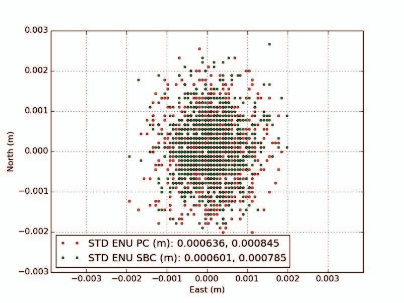
RF IC                                                          I+

                                                                                                                                    VGA              LP       I-

                                 LNA        Splitter                            Matching
             RF in                                                                                              0°                                            Ref
                                                                                Network
             SMA                                                                 50->75                              90°
                                                              BP                                 RF VGA                         PLL+VCO

                                                                                                                                                                       Base Unit Interface
                                                                                                                                                          Q+
                                                         Antenna
                                   Overcurrent
                                                          Power
                                    Detection
                                                          on/off                                                                    VGA              LP       Q-

                                                                                                                       I2C Configuration Interface

                                                                                                                                                              SCL
                                                                                                                                     I2C Extender
                                                                                                                                       EEPROM                 SDA

                                                                                                 DAC                                                          SPI
                        Low-dropout                                                               SPI
                         Regulator
                                                                                                                                                          Power

                                                                    Fig. 2. Block diagram of GOOFI frontend

                                            variable                                           RF-IC
                                 Amplifier Attenuator Amplifier Bandpass
                                                                                                                                                     A
                                                                                                                                                                    8bit
                                                                               BP                          BP                                 LP          D

             Passive antenna

                               Amplifier Duplexer                  Amplifier 4x Splitter                    PLL+VCO
                                   LNA                                  LNA         Splitter                Local
                                                                                                          Oscillator

                                                          Alternate
                                                          input for
                                                       active antenna

                                                                   Fig. 3. Block diagram of GOOFEX frontend

                       Test Number       Platform       1 sigma E (m)         1 sigma N (m)      max error E (m)       max error N (m)       GDoP    PDoP
                       1                    PC            2.44 (2.24)           2.74 (2.40)        9.12 (7.93)           9.80 (9.73)          1.9     1.7
                       2                    PC            1.77 (1.59)           3.38 (3.74)        5.20 (5.47)          12.95 (12.01)         1.8     1.6
                       3                   SBC            1.81 (1.82)           2.94 (2.82)        7.07 (7.42)          12.64 (13.61)         2.0     1.8
                       4                   SBC            1.90 (1.78)           2.84 (2.55)        6.54 (5.59)          11.45 (10.18)         2.2     1.9
                                                                       TABLE I
                                          E XTRACT OF MEASUREMENT CAMPAIGN FOR THE AUTONOMOUS POSITION TESTS

Authorized licensed use limited to: FhI fur Integrierte Schaltungen Angewandte Elek. Downloaded on February 05,2021 at 09:16:33 UTC from IEEE Xplore. Restrictions apply.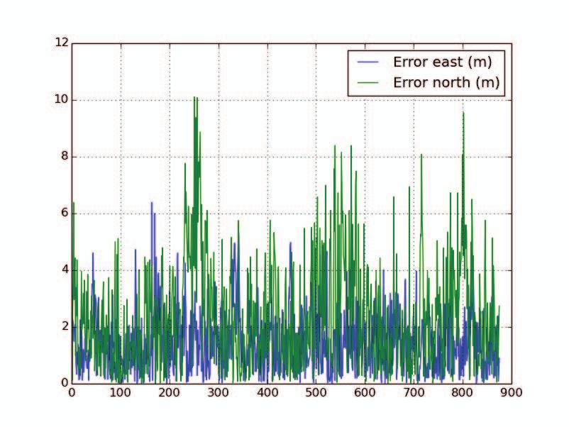
Test Number      Platform     1 sigma E (mm)      1 sigma N (mm)       max error E (mm)       max error N (mm)      GDoP      PDoP
                  5                   PC              0.63                0.84                 1.92                   2.55             2.4       2.1
                  6                   PC              0.94                1.55                 5.90                   6.44             2.2       2.0
                  7                  SBC              0.60                0.78                 1.99                   2.66             2.4       2.1
                  8                  SBC              0.87                1.26                 3.00                   5.10             2.0       1.8
                                                                       TABLE II
                                            E XTRACT OF THE MEASUREMENT CAMPAIGN FOR THE RTK POSITION TESTS

                                                                                      The results described in this paper show that the autonomous
                                                                                      position requires still improvements on the algorithmic, but
                                                                                      the RTK solution has a 3 mm position error and approx
                                                                                      1 mm precision, which is comparable with the ones provided
                                                                                      by commercial receivers. The results show no significant
                                                                                      difference for the PC and the SBC platform, which guarantees
                                                                                      that the GOOSE receiver can be used as a reliable development
                                                                                      chain.
                                                                                                                ACKNOWLEDGMENT
                                                                                        The GOOSE and the GalileoOnline project are funded by
                                                                                      the ”Bundesministerium für Wirtschaft und Energie” (German
                                                                                      Federal Ministry for Economic Affairs and Energy) which is
                                                                                      gratefully acknowledged.
                                                                                                                     R EFERENCES
                                                                                       [1] Javad, “TR-G3T,” http://www.javad.com/downloads/javadgnss/sheets/
    Fig. 11. Position error in East-North with SBC platform (RTK position test             TR-G3T Rev.5 Datasheet.pdf, October 2012.
    7)                                                                                 [2] Novatel, “OEM638,” http://www.novatel.com/assets/Documents/Papers/
                                                                                           OEM638-PS-D17916.pdf, Februar 2016.
                                                                                       [3] N. Shivaramaiah, J. Wu, J. W. Cheong, M. Choudhury, and K. Parkinson,
                                                                                           “Annex 5. Developing a Satellite Navigation Receiver for the Space
                                                                                           Mission,”      http://www.garada.unsw.edu.au/Final%20Report/Annex%
                                                                                           205.%20Developing%20a%20Satellite%20Navigation%20Receiver%
                                                                                           20for%20the%20Space%20Mission.pdf, June 2013.
                                                                                       [4] T. Paakki, J. Raasakka, F. Della Rosa, H. Hurskainen, and J. Nurmi,
                                                                                           “Tutgnss university based hardware/software gnss receiver for research
                                                                                           purposes,” in Ubiquitous Positioning Indoor Navigation and Location
                                                                                           Based Service (UPINLBS), 2010, Oct 2010, pp. 1–6.
                                                                                       [5] S. Sand, “Galileo Ready Advanced Mass MArket Re-
                                                                                           ceiver, Final Report,” DLR, Tech. Rep., 2011. [Online].
                                                                                           Available:    http://www.gsa.europa.eu/sites/default/files/virtual library/
                                                                                           GRAMMAR Project - Final Report.pdf
                                                                                       [6] Xilinx, “Axi memory mapped to pci express (PCIe) gen2 v2.6,”
                                                                                           http://www.xilinx.com/support/documentation/ip documentation/axi
                                                                                           pcie/v2 6/pg055-axi-bridge-pcie.pdf, February 2016.
                                                                                       [7] Freescale Semiconductor Inc., “i.MX 6dual/6quad applications proces-
                                                                                           sors for industrial products,” http://cache.freescale.com/files/32bit/doc/
                                                                                           data sheet/IMX6DQIEC.pdf, February 2016.
                                                                                       [8] “Smart mobility architecture,” https://en.wikipedia.org/wiki/Smart
                                                                                           Mobility Architecture, February 2016.
                                                                                       [9] Kontron, “SMARC-sAMX6i,” http://www.kontron.com/downloads/
                                                                                           datasheet/datasheet smarc-samx6i.pdf, February 2016.
    Fig. 12. Position in East-North with PC and SBC platform (RTK position            [10] “Ogrp - the open gnss receiver protocol,” https://github.com/
    test 5 and 7)                                                                          Fraunhofer-IIS/ogrp, February 2016.
                                                                                      [11] “0mq - the guide,” http://zguide.zeromq.org/page:all, February 2016.
                                                                                      [12] “Rtklib: An open source program package for gnss positioning,” http:
                                                                                           //www.rtklib.com/, February 2016.
    environments and to provide to the user a full access to the
    hardware features and the real-time measurement data. This
    open hardware interface is based on a protocol called OGRP
    which was developed in the GOOSE project. The protocol
    allows also to close the PLL / DLL / FLL tracking loops in an
    external user application which runs on the same host system.
    In the project GalileoOnline this feature will be exploited
    to implement external INS-aided and vector tracking loops.

Authorized licensed use limited to: FhI fur Integrierte Schaltungen Angewandte Elek. Downloaded on February 05,2021 at 09:16:33 UTC from IEEE Xplore. Restrictions apply.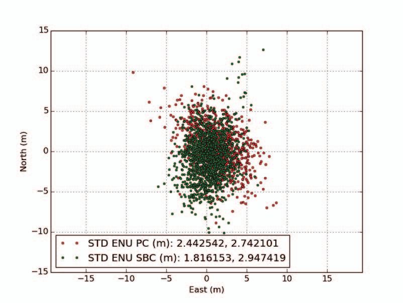
You can also read