Dev Board Datasheet Version 1.6 - Version 1.6 (July 2020) Copyright 2020 Google LLC. All rights reserved - Google Coral
←
→
Page content transcription
If your browser does not render page correctly, please read the page content below
Dev Board Datasheet
Version 1.6

Version 1.6 (July 2020)   Copyright 2020 Google LLC. All rights reserved.
Features
   Edge TPU System-on-Module (SoM)                             Audio connections

      NXP i.MX 8M SoC (Quad-core Arm Cortex-A53, plus             3.5 mm audio jack (CTIA compliant)
      Cortex-M4F)
                                                                  Digital PDM microphone (x2)
      Google Edge TPU ML accelerator coprocessor
                                                                  2.54 mm 4-pin terminal for stereo speakers
      Cryptographic coprocessor
                                                               Video connections
      Wi-Fi 2x2 MIMO (802.11b/g/n/ac 2.4/5 GHz)
                                                                  HDMI 2.0a (full size)
      Bluetooth 4.2
                                                                  39-pin FFC connector for MIPI DSI display (4-lane)
      8 GB eMMC
                                                                  24-pin FFC connector for MIPI CSI-2 camera (4-lane)
      1 or 4 GB LPDDR4
                                                               MicroSD card slot
   USB connections
                                                               Gigabit Ethernet port
      USB Type-C power port (5 V DC)
                                                               40-pin GPIO expansion header
      USB 3.0 Type-C OTG port
                                                               Supports Mendel Linux (derivative of Debian)
      USB 3.0 Type-A host port

      USB 2.0 Micro-B serial console port

Overview
The Coral Dev Board is a single-board computer that's ideal when you need to perform fast machine learning (ML)
inferencing in a small form factor. You can use the Dev Board to prototype your embedded system and then scale to
production using the on-board Coral System-on-Module (SoM) combined with your custom PCB hardware.

The SoM provides a fully-integrated system, including NXP's iMX 8M system-on-chip (SoC), eMMC memory, LPDDR4
RAM, Wi-Fi, and Bluetooth, but its unique power comes from Google's Edge TPU coprocessor. The Edge TPU is a small
ASIC designed by Google that provides high performance ML inferencing with a low power cost. For example, it can
execute state-of-the-art mobile vision models such as MobileNet v2 at almost 400 FPS, in a power efficient manner.

The baseboard provides all the peripheral connections you need to prototype a project, including USB 2.0/3.0 ports, DSI
display interface, CSI-2 camera interface, Ethernet port, speaker terminals, and a 40-pin I/O header.

Key benefits of the Dev Board:

   High-speed and low-power ML inferencing (4 TOPS @ 2 W)

   A complete Linux system (running Mendel, a Debian derivative)

   Prototyping and evaluation board for the small Coral SoM (40 x 48 mm)

Version 1.6 (July 2020)                                                      Copyright 2020 Google LLC. All rights reserved.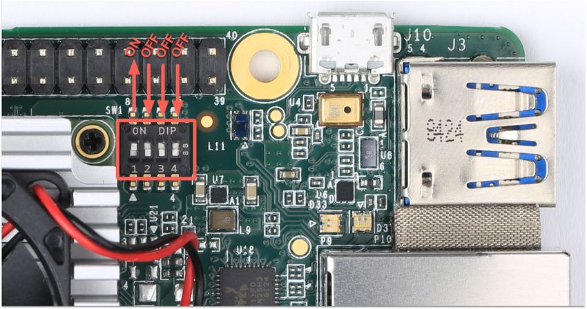
Ordering information

Part number           Description

G950-01455-01         Coral Dev Board with 1 GB RAM (part number varies by region)
G950-03970-01
G950-04742-01

G950-06210-01         Coral Dev Board with 4 GB RAM

Version 1.6 (July 2020)                                                    Copyright 2020 Google LLC. All rights reserved.
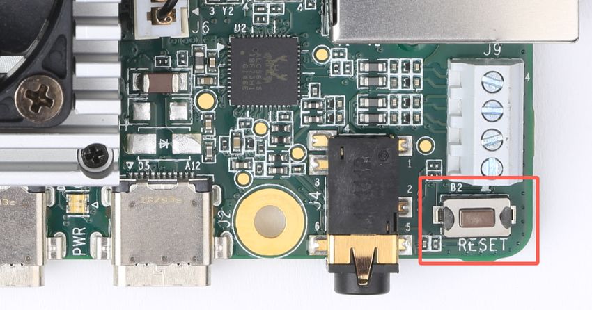
Table of contents
  System components
      Block diagrams
  Mechanical dimensions
  Baseboard connections
      I/O header pinout
      Serial console port
      HDMI port
      USB 3.0 ports
      Ethernet port
      4-pin stereo terminal
      MicroSD slot
      DSI display connector
      CSI-2 camera connector pinout
  System power
      Boot mode
      System reset
  Software and operation
  LED behavior
      Power LED
      Serial port LEDs
  SoM hardware details
  Recommended operating conditions
      Thermal solution
  Environmental and mechanical reliability tests
  Certifications
  Schematic and layout files
  Document revisions

Version 1.6 (July 2020)                            Copyright 2020 Google LLC. All rights reserved.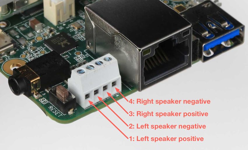
System components
Table 1. Available Dev Board components and features

 Feature                                      Details

 Main system-on-chip (i.MX8M)

 Arm Cortex-A53 MPCore platform               Quad symmetric Cortex-A53 processors:

                                                 32 KB L1 Instruction Cache

                                                 32 KB L1 Data Cache

                                                 Support L1 cache RAMs protection with parity/ECC

                                              Support of 64-bit Armv8-A architecture:

                                                 1 MB unified L2 cache

                                                 Support L2 cache RAMs protection with ECC

                                                 Frequency of 1.5 GHz

 Arm Cortex-M4 core platform                     16 KB L1 Instruction Cache

                                                 16 KB L1 Data Cache

                                                 256 KB tightly coupled memory (TCM)

 Graphic Processing Unit (GPU)                   Vivante GC7000Lite

                                                 4 shaders

                                                 267 million triangles/sec

                                                 1.6 Gigapixel/sec

                                                 32 GFLOPs 32-bit or 64 GFLOPs 16-bit

                                                 Supports OpenGL ES 1.1, 2.0, 3.0, 3.1, Open CL 1.2, and Vulkan

 Video Processing Unit (VPU)                     4Kp60 HEVC/H.265 main, and main 10 decoder

                                                 4Kp60 VP9 and 4Kp30 AVC/H.264 decoder (requires full system
                                                 resources)

                                                 1080p60 MPEG-2, MPEG-4p2, VC-1, VP8, RV9, AVS, MJPEG,
                                                 H.263 decoder

Version 1.6 (July 2020)                                                      Copyright 2020 Google LLC. All rights reserved.
Feature Details
I/O connectivity 2x USB 3.0/2.0 controllers with integrated PHY interfaces
1x Ultra Secure Digital Host Controller (uSDHC) interfaces
1x Gigabit Ethernet controller with support for EEE, Ethernet AVB,
and IEEE 1588
2x UART modules
2x I2C modules
2x SPI modules
16x GPIO lines with interrupt capability
4x PWM lines
Input/output multiplexing controller (IOMUXC) to provide
centralized pad control
Note: The list above is the number of signals available to the
baseboard (after considering SoC signals used by the SoM).
On-chip memory Boot ROM (128 KB)
On-chip RAM (128 KB + 32 KB)
External memory 32/16-bit DRAM interface: LPDDR4-3200, DDR4-2400, DDR3L-
1600
8-bit NAND-Flash
eMMC 5.0 Flash
SPI NOR Flash
QuadSPI Flash with support for XIP
Version 1.6 (July 2020) Copyright 2020 Google LLC. All rights reserved.Feature Details
Display HDMI Display Interface:
HDMI 2.0a supporting one display up to 1080p
Upscale and downscale between 4K and HD video (requires full
system resources)
20+ Audio interfaces 32-bit @ 384 kHz fs, with Time Division
Multiplexing (TDM) support
SPDIF input and output
Audio Return Channel (ARC) on HDMI
MIPI-DSI Display Interface:
MIPI-DSI 4 channels supporting one display, resolution up to
1920 x 1080 @ 60 Hz
LCDIF display controller
Output can be LCDIF output or DC display controller output
Audio 1x SPDIF input and output
2x synchronous audio interface (SAI) modules supporting I2S,
AC97, TDM, and codec/DSP interfaces
1x SAI for 8 Tx channels for HDMI output audio
1x SPDIF input for HDMI ARC input
Camera MIPI-CSI2 camera input (4-lane)
Security Resource Domain Controller (RDC) supports four domains and
up to eight regions
Arm TrustZone (TZ) architecture
On-chip RAM (OCRAM) secure region protection using OCRAM
controller
High Assurance Boot (HAB)
Cryptographic acceleration and assurance (CAAM) module
Secure non-volatile storage (SNVS): Secure real-time clock (RTC)
Secure JTAG controller (SJC)
ML accelerator
Version 1.6 (July 2020) Copyright 2020 Google LLC. All rights reserved.Feature Details
Edge TPU coprocessor ASIC designed by Google that provides high performance ML
inferencing for TensorFlow Lite models
Uses PCIe and I2C/GPIO to interface with the iMX 8M SoC
4 trillion operations per second (TOPS)
2 TOPS per watt
Memory and storage
Random access memory (SDRAM) 1 or 4 GB LPDDR4 SDRAM (4-channel, 32-bit bus width)
1600 MHz maximum DDR clock
Interfaces directly to the iMX 8M build-in DDR controller
Flash memory (eMMC) 8 GB NAND eMMC flash memory
8-bits MMC mode
Conforms to JEDEC version 5.0 and 5.1
Expandable flash (MicroSD) Meets SD/SDIO 3.0 standard
Runs at 4-bits SDIO mode
Supports system boot from SD card
Network & wireless
Ethernet 10/100/1000 Mbps Ethernet/IEEE 802.3 networks
Reduced gigabit media-independent interface (RGMII)
Wi-Fi Murata LBEE5U91CQ module:
Wi-Fi 2x2 MIMO (802.11a/b/g/n/ac 2.4/5GHz)
Supports PCIe host interface for W-LAN
Bluetooth Murata LBEE5U91CQ module:
Bluetooth 4.2 (supports Bluetooth low-energy)
Supports UART interface
Security
Cryptographic coprocessor Microchip ATECC608A cryptographic coprocessor:
Asymmetric (public/private) key cryptographic signature solution
based on Elliptic Curve Cryptography and ECDSA signature
protocols
Version 1.6 (July 2020) Copyright 2020 Google LLC. All rights reserved.Feature Details
Baseboard
Connectors 40-pin I/O header (see pinout below)
USB Micro-B for serial console
USB 3.0 Type-A host
Gigabit Ethernet
4-pin stereo terminal
3.5 mm audio jack
USB Type-C power
USB Type-C data
HDMI 2.0a (full size)
MicroSD slot
MIPI DSI display (39-pin flat flex cable)
MIPI CSI-2 camera (24-pin flat flex cable)
Version 1.6 (July 2020) Copyright 2020 Google LLC. All rights reserved.Block diagrams Figures 1 and 2 illustrate the core components on the baseboard and SoM. Figure 1. Block diagram of the baseboard components Version 1.6 (July 2020) Copyright 2020 Google LLC. All rights reserved.
Figure 2. Block diagram of the SoM components

Version 1.6 (July 2020)                         Copyright 2020 Google LLC. All rights reserved.
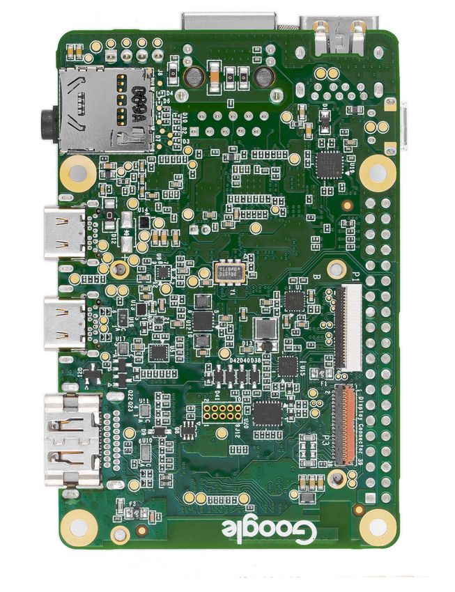
Mechanical dimensions

Figure 3. Coral Dev Board dimensions

Version 1.6 (July 2020)                Copyright 2020 Google LLC. All rights reserved.
Baseboard connections
The baseboard on the Coral Dev Board provides a variety of connectors as shown in figure 4.

Figure 4. Connectors on the Coral Dev Board

I/O header pinout
All I/O pins on the 40-pin header are powered by the 3.3 V power rail, with a programmable impedance of 40-
255 ohms, and a max current of ~82 mA.

All I/O pins have a 90k pull-down resistor inside the iMX 8M SoC that is used by default during bootup, except for the
I2C pins, which instead have a pull-up to 3.3 V on the SoM. However, these can all be changed with a device tree
overlay that loads after bootup.

You can interact with each pin using standard Linux interfaces such as device files (/dev) and sysfs files (/sys). For
usage information, see Connect to the Dev Board I/O pins.

 Caution: Do not connect a device that draws more than ~82 mA of power or you will brownout the
 system.

Version 1.6 (July 2020)                                                         Copyright 2020 Google LLC. All rights reserved.
Table 2. Pinout for the 40-pin I/O header. (For detailed usage information, see Connect to the Dev Board I/O pins.)

 SoC signal name          Baseboard signal     Header pins    Baseboard signal     SoC signal name

                              +3.3 V power        1   2       +5 V power

         I2C2_SDA                I2C2_SDA         3   4       +5 V power

          I2C2_SCL               I2C2_SCL         5   6       Ground

       UART3_TXD               UART3_TXD          7   8       UART1_TXD            UART1_TXD

                                   Ground        9    10      UART1_RXD            UART1_RXD

       UART3_RXD              UART3_RXD          11   12      SAI1_TXC             SAI1_TXC

             GPIO6               GPIO_P13        13   14      Ground

             PWM3                   PWM3         15   16      GPIO_P16             NAND_DATA03

                              +3.3 V power       17   18      GPIO_P18             ECSPI2_SCLK

       ECSPI1_MOSI            ECSPI1_MOSI        19   20      Ground

       ECSPI1_MISO            ECSPI1_MISO        21   22      GPIO_P22             ECSPI2_MISO

       ECSPI1_SCLK            ECSPI1_SCLK       23    24      ECSPI1_SS0           ECSPI1_SS0

                                   Ground       25    26      ECSPI1_SS1           ECSPI1_SS1

         I2C3_SDA                I2C3_SDA        27   28      I2C3_SCL             I2C3_SCL

             GPIO7               GPIO_P29       29    30      Ground

             GPIO8               GPIO_P31        31   32      PWM1                 PWM1

             PWM2                   PWM2        33    34      Ground

         SAI1_TXFS               SAI1_TXFS      35    36      GPIO_P36             ECSPI2_SS0

   NAND_DATA07                   GPIO_P37        37   38      SAI1_RXD0            SAI1_RXD0

                                   Ground       39    40      SAI1_TXD0            SAI1_TXD0

Key:

 Synchronous Audio         Serial Peripheral                 General Purpose     +5 V power
 Interface (SAI)           Interface (SPI)                   I/O (GPIO)

 Inter-Integrated          Universal Asynchronous            Ground              +3.3 V power
 Circuit (I2C)             Receiver-Transmitter (UART)
Version 1.6 (July 2020)                                                           Copyright 2020 Google LLC. All rights reserved.
Universal Asynchronous Receiver-Transmitter (UART) Each UARTv2 module supports the following: 7- or 8-bit data words, 1 or 2 stop bits, programmable parity (even, odd, or none). Programmable baud rates up to 4 Mbps. 32-byte FIFO on Tx and 32 half-word FIFO on Rx supporting auto-baud. Note: By default, the Mendel operating system configures UART1 for use with the the serial console. Synchronous Audio Interface (SAI) Each SAI module supports full duplex serial interfaces with frame synchronization, such as I2S, AC97, TDM, and codec/DSP interfaces. Inter-Integrated Circuit (I2C) Serial interface for external devices. Serial Peripheral Interface (SPI) Full-duplex enhanced Synchronous Serial Interface, with data rate up to 52 Mbit/s. Configurable to support Master/Slave modes, four chip selects to support multiple peripherals. Pulse Width Modulation (PWM) Operates on a frequency of 0-66 Mhz. Provides a 16-bit counter and is optimized to generate sound from stored sample audio images. It can drive motors and generate tones. It uses 16-bit resolution and a 4x16 data FIFO to generate sound. Serial console port The micro-USB port (see "serial console" in figure 4) provides access to the serial console based on the CP210x USB to UART Bridge Controller. Only Linux and Mac are officially supported for serial console connections, as follows. Version 1.6 (July 2020) Copyright 2020 Google LLC. All rights reserved.
Connect with Linux
 . Run the following commands to add the required udev rule:

     sudo sh -c "echo 'SUBSYSTEM==\"usb\", ATTR{idVendor}==\"0525\", MODE=\"0664\", \
     GROUP=\"plugdev\", TAG+=\"uaccess\"' >> /etc/udev/rules.d/65-edgetpu-board.rules"

     sudo udevadm control --reload-rules && udevadm trigger

 . Determine the device filename for the serial connection by running this command on your Linux computer:

     dmesg | grep ttyUSB

  You should see two results such as this:

     [ 6437.706335] usb 2-13.1: cp210x converter now attached to ttyUSB0
     [ 6437.708049] usb 2-13.1: cp210x converter now attached to ttyUSB1

 . Use the name of the first filename listed as a cp210x converter to open the serial console connection (this
   example uses ttyUSB0 as shown from above):

     screen /dev/ttyUSB0 115200

Connect with Mac
 . Install the following device driver.

    Caution: Before installing the following package, be sure you've applied all available macOS software
    updates. Otherwise, you might be blocked from installing due to system security that disables the Allow
    button in System Preferences.

  Install the CP210x USB to UART Bridge Virtual COM Port (VCP) driver for Mac.

 . Connect with this command:

     screen /dev/cu.SLAB_USBtoUART 115200

Version 1.6 (July 2020)                                                     Copyright 2020 Google LLC. All rights reserved.
Help! If screen prints Cannot access line '/dev/ttyUSB0', then your Linux user account is not in the
plugdev and/or dialout system group. Ask your system admin to add your account to both groups, and
then restart your computer for it to take effect.
If you see [screen is terminating], it might also be due to the system groups, or there's something else
wrong with screen—ensure all screen sessions are closed (type screen -ls to see open sessions), unplug the
USB cable from the Dev Board, and then try again.
Tip: You can also connect to the board via MDT (only with boards running Mendel 3.0 or higher).
HDMI port
This is a full-size HDMI 2.0a port.
By default, the output is locked at a resolution of 1920 x 1080 to avoid GPU pressure and power costs when driving
higher resolution displays.
If your display does not support 1920 x 1080, you can change this setting by editing file at
/etc/xdg/weston/weston.ini: In the [output] section, edit the line mode=1920x1080 to be a resolution of your choice.
You may also delete this line completely, and it will then use the highest resolution supported by the monitor (but doing
so can degrade the overall system performance if it is higher than 1920x1080).
USB 3.0 ports
There are three USB 3.0 ports:
USB Type-A host: Operates as a USB 3.0 host that can provide power. Use this port for your peripherals, such as a
USB camera.
Caution: Do not connect a device that draws more than 1 A of power or you will brownout the system.
USB Type-C data: Operates as a USB "on the go" (OTG) device port, so the Dev Board appears as a USB device to a
connected host device. Use this port to connect to the shell over USB or to flash the board.
USB Type-C power: Use this to power the board with a 2-3 A at 5 V DC connection.
Ethernet port
The Gigabit Ethernet port (RJ45) supports 10/100/1000 Mbps Ethernet/IEEE 802.3 networks.
Version 1.6 (July 2020) Copyright 2020 Google LLC. All rights reserved.4-pin stereo terminal We recommend using a 4 ohm, 3 watt speaker. A higher ohmage results in a much quieter output. The stereo terminal is a 4-pin 2.54 mm-pitch terminal connector for stereo speakers. Wire functions are as follows (from left to right, as shown in figure 5): 1: Speaker left positive 2: Speaker left negative 3: Speaker right positive 4: Speaker right negative Figure 5. Stereo speaker terminals MicroSD slot The MicroSD card meets the SD/SDIO standard, up to version 3.0. It can be used as expanded memory for the system or as the disk for the system image. If the entire system fails, you can use the SD card to reflash U-Boot onto the board (see the flashing instructions). Version 1.6 (July 2020) Copyright 2020 Google LLC. All rights reserved.
MIPI DSI display connector
The MIPI DSI display connector is a 39-pin flex cable connector that provides 4 lanes with resolution up to 1920x1080 at
60 Hz. The connector pinout is as follows.

Table 3. MIPI DSI pinout

 Pin #    Name                      Pin #   Name

 1        GND                       21      DSI_TE

 2        ---TP5                    22      ---

 3        ---TP20                   23      V1V8

 4        ---TP2                    24      ---

 5        GND                       25      DISP_LEDA

 6        MIPI_DSI_D2_P             26      DISP_LEDK1

 7        MIPI_DSI_D2_N             27      DISP_LEDK2

 8        GND                       28      VOP_5p5_CONN

 9        MIPI_DSI_D1_P             29      VON_N5p5_CONN

 10       MIPI_DSI_D1_N             30      LED_PWM

 11       GND                       31      GND

 12       MIPI_DSI_CLK_P            32      GND

 13       MIPI_DSI_CLK_N            33      --- TP21

 14       GND                       34      GND

 15       MIPI_DSI_D0_P             35      DISPLAY_I2C_SCL_1V8

 16       MIPI_DSI_D0_N             36      DISPLAY_I2C_SDA_1V8

 17       GND                       37      DSI_VSP_EN

 18       MIPI_DSI_D3_P             38      DSI_TS_nINT

 19       MIPI_DSI_D3_N             39      DSI_RESETB

 20       GND

Version 1.6 (July 2020)                                                       Copyright 2020 Google LLC. All rights reserved.
MIPI CSI-2 camera connector pinout
The MIPI CSI-2 camera connector is a 24-pin flex cable connector that's designed for the Coral Camera. The connector
pinout is as follows.

Table 4. Pinout for camera cable connector

 Pin    Name                   Pin   Name

 1      GND                    13    GND

 2      MIPI_CSI_D0_N          14    MIPI_CSI_D3_N

 3      MIPI_CSI_D0_P          15    MIPI_CSI_D3_P

 4      GND                    16    GND

 5      MIPI_CLK_N             17    CAM_PWDNB

 6      MIPI_CLK_P             18    CAM_CLK (NC)

 7      GND                    19    GND

 8      MIPI_CSI_D1_N          20    CAM_I2C_SCL

 9      MIPI_CSI_D1_P          21    CAM_I2C_SDA

 10     GND                    22    CAM_VSYNC (NC)

 11     MIPI_CSI_D2_N          23    CAM_RESETB

 12     MIPI_CSI_D2_P          24    3.3V

Version 1.6 (July 2020)                                                     Copyright 2020 Google LLC. All rights reserved.
Figure 6. Camera adapter card diagram

Version 1.6 (July 2020)                 Copyright 2020 Google LLC. All rights reserved.
System power
The Coral Dev Board must be powered by 2-3 A at 5 V DC using the USB Type-C power port (see figure 4).

 Caution: Do not attempt to power the board by connecting it to your computer.

The SoM has one primary PMIC (BD71837MWV) from Rohm for the iMX 8M SoC complex, LPDDR4, eMMC, and Wi-
Fi/Bluetooth. It integrates 8 DC-DC buck regulators and 7 LDOs to provide all power rails required by iMX 8M SoC and
commonly used peripherals.

Boot mode
The baseboard includes 4 switches (indicated in figure 7 to control the boot mode. By default, they are set to boot from
eMMC. You can change the boot mode as follows.

Table 5. Boot mode switches

 Boot mode                Switch 1   Switch 2   Switch 3       Switch 4

 Serial download          Off        On         [Don't care]   [Don't care]

 eMMC                     On         Off        Off            Off

 SD card                  On         Off        On             On

Figure 7. Boot mode switches, set to boot from eMMC

Version 1.6 (July 2020)                                                       Copyright 2020 Google LLC. All rights reserved.
System reset
You can restart the system with the RESET button shown in figure 8.

Figure 8. System reset button

Software and operation
The Dev Board factory setting includes only the U-Boot bootloader software on the eMMC memory. To use the board,
you need to flash the Mendel operating system (a derivative of Debian Linux). For instructions, see the Get started
guide.

The Mendel system includes software that's specially-designed for the Dev Board and required to operate the Edge TPU.
It also includes Python APIs that make it easy to perform inferences with TensorFlow Lite models.

For information about how to create models and run inferences on the Edge TPU, read TensorFlow models on the Edge
TPU.

 Caution: Avoid touching the heat sink during operation. Whether or not the fan is running, the heat sink
 can become very hot to the touch and might cause burn injuries.

Version 1.6 (July 2020)                                                     Copyright 2020 Google LLC. All rights reserved.
Caution: Do not unplug the Dev Board to shut it down. Doing so could corrupt the system image if any
 write operations are in progress. Instead, safely shutdown the system with the following command:

    sudo shutdown now

 When the red LED on the Dev Board turns off, you can unplug the power.

LED behavior
The Dev Board has two sets of on-board LED lights: one LED for power status, and a pair of LEDs providing the status of
the serial port.

The Ethernet port also has a pair of LED lights.

Power LED
The LED that provides power status is situated between the Power (PWR) and USB On-The-Go (OTG) ports. It lights up
red when the board is powered up and switches off when either power is removed or the main SoC is shut down (for
example, when a sudo shutdown command is issued).

Serial port LEDs
The board has green and yellow LEDs near the serial console connector (USB micro-B), those show TX/RX activity via
serial interface. The green LED lights up when there is activity on the RX line (indicating data is being received over the
serial interface), while the yellow LED lights up when there is activity on the TX line (indicating that data is being
transmitted over the serial interface).

SoM hardware details
The system-on-module (SoM) included with the Dev Board is based on NXP's iMX 8M system-on-chip (SoC) and
contains all the essential system hardware, including the Edge TPU and Wi-Fi/Bluetooth radios. It is attached to the Dev
Board baseboard with three 100-pin board-to-board connectors.

 Note: If you are interested in using the Coral SoM with custom PCB hardware (instead of the baseboard
 provided with the Dev Board), you can learn more about the standalone SoM in the Coral SoM datasheet.

Figure 9 shows the dimensions of the SoM.

Version 1.6 (July 2020)                                                          Copyright 2020 Google LLC. All rights reserved.
Figure 9. Coral SoM dimensions without the heat sink and fan Recommended operating conditions To ensure reliable operation and performance, the board should operate in the following environment: Temperature: 0-50° C Thermal solution To maintain functional heat levels the Dev Board includes a heat sink and a fan with the following specifications: Speed: 9k RPM Airflow: 138 LPM (4.9 CFM) Voltage: 5 V DC Power (peak): 0.65 W Static pressure: 42 Pa (0.17 in-H2O) Caution: Avoid touching the heat sink during operation. Whether or not the fan is running, the heat sink can become very hot to the touch and might cause burn injuries. Version 1.6 (July 2020) Copyright 2020 Google LLC. All rights reserved.
Environmental and mechanical reliability tests
Table 6. Verified results for environmental and mechanical reliability tests

 Test                              Conditions                                                                      Verified

 Temp cycling                      Non-op, -40° C (LT) to 85° C (HT), 7 minute ramp, 23 minutes dwell,             200 cycles
                                   60 minutes/cycle

 Heat soak                         Non-op, 85° C @ 85% RH                                                          200 cycles

 Audio jack cycling                50% manual plug/unplug, 50% uniaxial machine plug/ unplug                       1000 cycles

 HDMI cycling                      Manual plug/unplug                                                              100 cycles

 MicroSD cycling                   Manual plug/unplug                                                              100 cycles

 Vibration                         3 axes (X, Y and Z), 15 minutes per axis, 10-500 Hz. Amplitude:                 45 minutes
                                   2.16 Grms

 USB-C connector                   Manual plug/unplug                                                              1000 cycles
 cycling

 USB-A connector                   Manual plug/unplug                                                              1000 cycles
 cycling

 Micro USB connector               Manual plug/unplug                                                              1000 cycles
 cycling

 Fan run life                      40°C, 65% RH                                                                    70k hours

Certi cations
Table 7. Dev Board certifications

 Country                  Agency

 USA                      FCC

 European Union           CE

 Hong Kong                CE

 Japan                    VCCI

 Korea                    KC

 Ghana                    NCA
Version 1.6 (July 2020)                                                           Copyright 2020 Google LLC. All rights reserved.
Country Agency
Taiwan BSMI/NCC
Australia RCM
New Zealand RCM
India WPC
Thailand NBTC
Singapore IMDA
Oman TRA
Philippines NTC
Schematic and layout les
Table 8. Dev Board schematics, layout, and 3D files
File Description
Coral-Dev-Board-baseboard-schematic.pdf Baseboard schematic in PDF
Coral-Dev-Board-baseboard-schematic- Baseboard schematic files in Altium format
Altium.zip
Coral-Dev-Board-baseboard-layout-Allegro.brd Baseboard CAD layout in BRD format
Coral-Dev-Board.STEP Dev Board (baseboard and SoM) 3D CAD file in STEP
format
Version 1.6 (July 2020) Copyright 2020 Google LLC. All rights reserved.Document revisions
Table 9. History of changes to this document
Version Changes
1.6 (July 2020) Added part numbers for all SKU variants.
1.5 (June 2020) Correction to MIPI-CSI2 count.
1.4 (April 2020) Updated the 40-pin I/O header pinout to be searchable.
1.3 (January 2020) Added information on LED behavior.
1.2 (August 2019) Added schematic and layout files
1.1 (August 2019) Camera cable pinout corrected.
1.0 (June 2019) Removed SoM hardware details (now instead see the SoM datasheet)
Added Edge TPU performance details
Added table captions
Retitled some sections
Miscellaneous copy edits
Beta (March 2019) Initial release
Version 1.6 (July 2020) Copyright 2020 Google LLC. All rights reserved.You can also read