1500 Series, Gen 2 Solar Air Heater / Solar Furnace Owner's Manual
←
→
Page content transcription
If your browser does not render page correctly, please read the page content below
1500 Series, Gen 2 Solar Air Heater / Solar Furnace
                                   Owner’s Manual

                                V4, Released 05.28.2021 to print
                                       Questions? Issues?

    Email: info@arcticasolar.com | Website: www.arcticasolar.com |Phone: (714)-698-9779

Copyright 2021, Arctica Solar. All Rights Reserved                                        1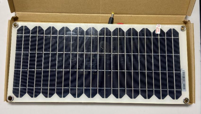
Thank you for purchasing the Arctica Solar 1500 Series Solar Air Heater / Solar Furnace, Gen 2 design.

This heater is a simple product, and with proper installation and maintenance should bring you years of
free, renewable, supplemental heating to the adoptive space. Under full sunlight it can generate close
to 1,500 W / 5,000 BTU / hr of space heating.

This manual will guide you through the following Sections with regards to your new solar air heater. We
recommend you read the entire owner’s manual and install guidance before attempting to install your
new heater. Careful installation is the number one factor in ensuring a long, successful heater lifetime!

Sections:
    1.   Items included and not included with the heater purchase – Pg 3
    2.   Tools required for heater prep and installation – Pg 7
    3.   Preparation of the heater for installation – Pg 7
    4.   South Facing Vertical Wall Installation (recommended) – Pg 13
    5.   Mounting and connection to the 10W Solar Panel – Pg 20
    6.   Interior vent covers and intake air filtration – Pg 21
    7.   Connection to the Heat-Only Thermostat – Pg 22
    8.   Heater Lifetime Care Guide – Pg 23
             8.1 Washing intake filter
             8.2 Cleaning heater front glass
             8.3 Preparing for off season (summer)
             8.4 Cleaning ducting
             8.5 Replacing fan
             8.6 Removal, cleaning and replacement of front glass and / or absorber

   Copyright 2021, Arctica Solar. All Rights Reserved                                               2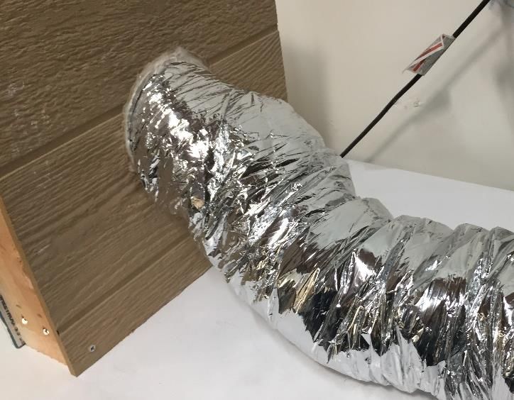
Section 1.0 - Items Included and not Included with the Heater
The following items are included with your heater shipment.

•   1x 1500 SERIES SOLAR AIR HEATER, GEN 2

•   2X WALL MOUNTING BRACKETS – for securing heater via the short sides to wall during mounting

•   1X HEAT ONLY THERMOSTAT – for optional use

    Copyright 2021, Arctica Solar. All Rights Reserved                                        3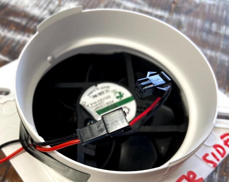
•   1X INTAKE COLLAR WITH FAN ASSEMBLY + THERMAL SWITCH + THERMOSTAT WIRE – draws COOL
    air in

•   1X EXHAUST COLLAR WITH GRAVITY DAMPER – allows HOT air out

•   8X SELF TAPPING #2 SELF DRILL SCREWS – 4x per intake and exhaust collar attachment to the heater
    back.

    Copyright 2021, Arctica Solar. All Rights Reserved                                          4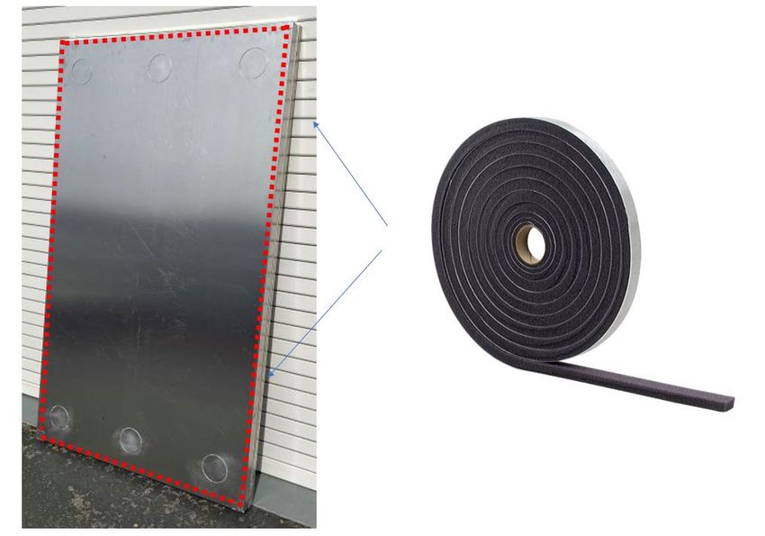
• 4X STAINLESS LAG BOLTS + WASHERS – For wall attach of mounting brackets supporting the heater
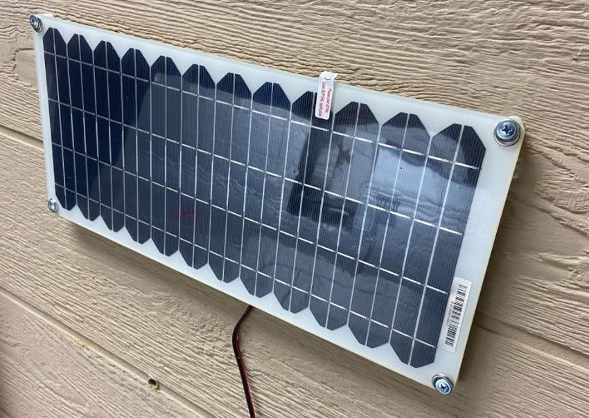
• 1X 10W SOLAR PANEL WITH MALE DC OUT + MOUTING STANDOFFS – for plugging into intake collar
assembly power in
• 1X WASHABLE FOAM INTAKE COLLAR FILTER – to filter the intake air stream before it enters the
heater
Copyright 2021, Arctica Solar. All Rights Reserved 5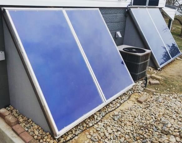
•   1X TEMPLATE OR SKETCH OF TEMPLATE PATTERN TRACED ONTO THE SHIPPING BOX – for installer
    to cut out and use as template for location of chosen intake and exhaust holes in your specific install

•   THIS OWNERS MANUAL – also available digitally from our website

Items Not Included:

These items are likely needed to complete your installation but are not provided with the heater itself.
They are typically in stock inventory at nearly all big box hardware stores (Lowes, Home Depot, ect)

•   4” ducting / flexible insulated ducting (available from all big box hardware stores)

•   2x (one for intake, one for exhaust) indoor duct cover / air duffers, more styles available online

    Copyright 2021, Arctica Solar. All Rights Reserved                                                   6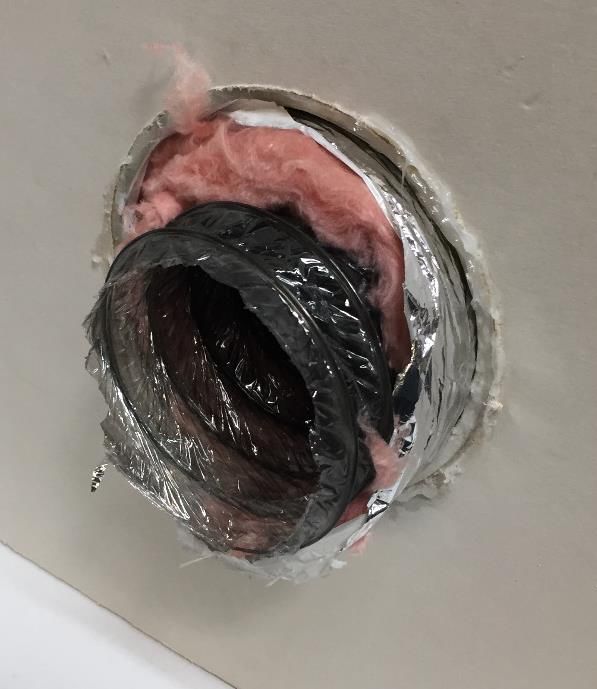
•   Metalized duct tape & weather stripping – for sealing heater back against the wall and other air gaps

•   Silicone adhesive (GE Silicone #1) or sealant for airtight collar attach or other sealing of air gaps post
    installation.

Section 2.0 – Tools required for heater preparation and installation
These are the tools likely required for preparation and installation of your heater in your application.

Tools:

-   For clothes dryer style non-insulated duct routing – Cordless drill, a 4” hole drill bit – available at
    most hardware stores.

-   For insulated / insulated flexible ducting – Cordless drill, a 6 3/8” hole drill bit – available at most
    hardware stores in electrical section, common tool for recessed lighting installation.

-   For prepping the heater – Snip pilers, box knife with 1” blade, cordless drill, common drill bits,
    impact driver with hex & Philips bits OR Philips head screwdriver.

-   For mounting – Cordless drill, common drill bits, caulking gun, impact driver with hex & Philips bits
    OR Philips head screwdriver and monkey wrench.

Section 3.0 – Preparation of the heater for installation
Let us review some overall details and physical dimensions of the heater. Figure 1 shows the heater
physical size dimensions which may be useful in sizing its permanent location or deciding how many
heaters are needed in your application. Figure 2 shows the intake and exhaust punch locations and
details. Figure 3 shows how the 2x mounting brackets interface with the heater to provide mounting
support. Figure 4 shows the heater front dimensions with mounting brackets in place.

    Copyright 2021, Arctica Solar. All Rights Reserved                                                        7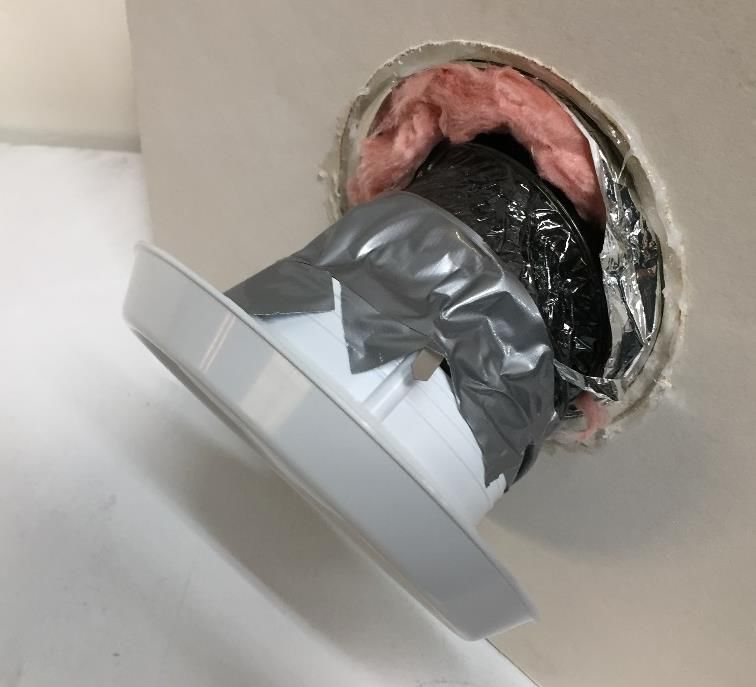
Figure 1: 1500 Heater Physical Dimensions

                                                    Figure 4: Heater dimensions with mounting brackets

   Copyright 2021, Arctica Solar. All Rights Reserved                                            8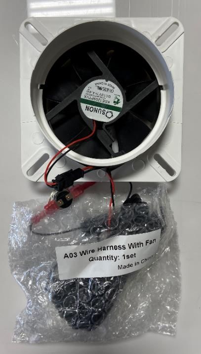
3.1. Determine where to mount your heater

3.1.1. Using the provided mounting template as a guide, find the location of the wall studs in the area
you want to mount the heater. If you have purchased a single heater, then the template is traced into
the back side of the box used for shipping. If you’ve purchase multiple heaters, a separate cardboard
template is provided as part of the freight shipment.

3.1.2. With mounting area and location of the wall studs identified, determine which 1x of the 3x
exhaust punchout options you will use, and which 1x of the 3x intake punchout options you will use in
your installation. The heater needs to undergo preparation before being ready for permanent
installation, namely install of the exhaust collar and intake collar + fan assembly.

3.1.3. We are now going to install the intake and exhaust collars onto the rear of the heater. Using
hand snips, remove the aluminum punchouts for the exhaust and intake locations you wish to use.
Exhaust and intake need to be located on opposing ends of the heater. Heater can be mounted portrait
or landscape, as guided in Section 4.0.

   Copyright 2021, Arctica Solar. All Rights Reserved                                              9
3.2. Install the thermal switch, wire harness, intake and exhaust collars

3.2.1. Using a box knife or razor with a 1.0-1.5” blade, remove the insulation from behind the selected
exhaust and intake punchouts. Vacuum out any loose insulation from the hole and interior of the heater
in both locations.

3.2.2. Insert into the exhaust hole the thermal switch, secure into the interior of the heater with a
small piece of duct tape. Use duct tape to prevent switch wiring from scraping against sharp edge of
heater box exhaust hole and possibly shorting or fraying. The thermal switch is OPEN when the heater is
below 30 C and CLOSED when the interior of the heater is above 30 C and ready to deliver useful
heating.

3.2.3. For the exhaust collar, place a bead of silicone sealant on the back of the heater around the
perimeter of the exhaust hole. Then with the gravity damper in the proper orientation for your install,
insert the exhaust collar and secure in place with the 4x provided self-tapping sheet metal screws to the
back plane of the heater. You may want to use a small drill bit to first create a pilot hole for each screw,
and then use an impact driver or screwdriver to start and fully seat each self-tapping screw.

  Copyright 2021, Arctica Solar. All Rights Reserved                                                   10
3.2.4. Using duct tape, tape into place the thermal switch wires to the back of the heater and route
the wires down to the determined intake collar location. Repeat Step 3.2.3 with the intake collar (with
fan already installed. BE SURE to orient the collar such THAT THE STICKER ON THE FAN POINTS INTO
THE INTERIOR OF THE HEATER). Be sure to route FAN power wires back out of the underside of the
collar for connection to the 10W SOLAR PANEL. Use duct tape to guard wires from fraying against the
sharp edge of the heater box intake collar hole, as we did with the thermal switch wires in the exhaust
hole – bottom right picture of Step 3.2.2.

  Copyright 2021, Arctica Solar. All Rights Reserved                                               11
Intake collar after installation with its proper orientation and with proper routing of the fan power lead
   to the exterior of the heater. Let the fan power lead dangle near the bottom OR side of the heater,
 depending on your install orientation. Secure the intake collar with a silicone bead and 4x self-tapping
                  sheet metal screws, same process as with the exhaust collar, Step 3.2.3.

3.2.5. The heater is now ready for installation. We recommend installing on a south or southwest
facing vertical wall that receives plenty of winter season sunlight, as covered in Section 4.0.

  Copyright 2021, Arctica Solar. All Rights Reserved                                                  12
Section 4.0 – South facing vertical wall installation (recommended)
4.1. Making intake and exhaust holes and routing of ducting into the space
An exhaust (hot air) hole and intake (cool air) hole must be added to the adoptive structure. The
cardboard template included with your heater and can be used to locate the selected intake and
exhaust ducting holes. Be sure to avoid placing planned intake and exhaust locations overtop wall studs.
If routing through a wall with no vapor barrier and no need for insulation of ducting:
The process can be done in two ways. First is similar to the installation of a 4” dryer duct, as seen in
videos referenced below. Locate wall studs prior to drilling to ensure that they will not interfere with
the path of the heater ducting. It is best to mount the heater closest to the point of use as possible to
cut down on heat loss through the transport of air to the use space, and fan pressure head loss.
These videos can serve as reference to this part of the installation process:
YouTube: How to install fume hood – link: https://youtu.be/9egwOazPJis
YouTube: How to install dryer duct – link: https://youtu.be/HjK2ybx8-14
Copyright 2021, Arctica Solar. All Rights Reserved 13If routing through a wall where sealing the vapor barrier is required: The use of insulated ducting is recommended. We recommend using a 6” PVC tube installed as a conduit for the flexible insulated ducting as seen in the process below. Use a 6 3/8” hole bit to place a through hole on the exterior wall and opposite interior wall. Create holes such that there is a slight downward angle from interior to exterior to discourage moisture from entering the exterior hole and flowing inwards. Feed a 6” PVC tube and cut leaving ¼” proud of the interior wall and exterior wall. Seal to interior wall and exterior wall (or vapor barrier) with a vapor barrier membrane or silicone sealant. Secure the conduit physically to the wall as needed. This tube will act as the conduit for the flexible ducting. Route 4” insulated ducting into the conduit. Secure the inner membrane of the interior side ducting to the end of a 6” air diffuser with duct tape as shown. Copyright 2021, Arctica Solar. All Rights Reserved 14
A 6” interior air diffuser can now fit snugly into the 6” PVC conduit. Cut the exterior insulated ducting to
the wall thickness (red arrow) but allow for extra interior ducting (which will compress back into the
wall) to make connecting to the heater intake and exhaust collars easier.

4.2.    Connecting the ducting to the heater exhaust and intake collars

Heater exhaust and intake collars interface with 4” ducting. Secure the duct to the collar using a screw
clamp or duct tape. Once connected slide insulation and vapor barrier back over the clamp and wrap
with duct tape or an additional screw clamp to secure in place.

  Copyright 2021, Arctica Solar. All Rights Reserved                                                   15
4.3.    Mounting the heater to the wall

Before securing the wall, we recommend placing a strip of appropriately thick weather stripping along
the perimeter of the back surface of the heater. This will discourage dust, debris, moisture, ect from
accumulating between the heater and the install wall during its lifetime. Select the thickness of weather
stripping appropriate for your mounting wall texture or type. Not required but recommended.

When deciding where to place the heater on the install wall, the selected heater intake and exhaust
locations should fit between the structure exterior wall studs, as seen below in a caddy-corner exhaust
and intake selection design.

  Copyright 2021, Arctica Solar. All Rights Reserved                                                16
With the heater install location determined, heater prepared for installation, the exhaust and intake
holes prepared, and duct routed and connected, we are ready to mount the heater. We recommend
using a minimum of 2x people to HOLD IN PLACE the heater level against the installation wall with intake
and exhaust collars properly connected to ducting and routed into the use space.

Then using a 3rd person, place the Bottom Mounting Bracket and match drill the bottom lip of the
bracket to the wall stud locations. Use a 5/32” bit to the proper depth to establish a pilot hole into the
stud for the lag bolt installation. Attach the bracket level to the wall capturing the bottom short side of
the heater with ¼” stainless, 2.5” length lag bolts with ¼” stainless washers (provided) into a minimum
of 2x studs per bracket.

Alternatively, the bottom mounting bracket can be installed prior to heater placement provided the
intake duct hole is large enough to accept the intake collar as it is tilted into place against the wall. The
heater can then be inserted into the bottom bracket and tilted back vertical against the wall and held in
place by the installer until the top bracket is also installed.

  Copyright 2021, Arctica Solar. All Rights Reserved                                                    17
Take care to properly route fan power female lead out the side or bottom of the heater and away from
being crimped by the bottom mounting bracket. The installer may want to drill a hole in the bottom
mounting bracket to route the fan power lead through it. The mounting brackets are designed to be
modified on the job site for proper routing of the fan power lead and connection to wall studs in the
specific installation. The mounting bracket may also have a side weld missing or removed to allow a
path for proper water drainage. In areas of heavy moisture exposure, the installer may want to add
additional holes for water effective water drainage out of the bottom mounting bracket.

With bottom bracket secured, install the Top Mounting Bracket by repeating the match drill, pilot and
attachment steps used for the Bottom Mounting Bracket. The heater should be snug in its mounting
brackets, but do not over torque as to provide too much stress into the heater or its glass.

The heater is now properly captured between the top and bottom mounting brackets and should be
secured for its operational lifetime (Section 3, Figures 3 & 4).

Other mounting options

The heaters can be mounted in a host of alternative configurations, including but not limited to the
following. The installation principles are the same as discussed for the portrait vertical wall mount.

1. Landscape wall mounting

When mounting landscape on a vertical wall, you do not get the benefit of natural convection helping
with air circulation, but since the heater uses a powered fan, this is not strictly required.

  Copyright 2021, Arctica Solar. All Rights Reserved                                                     18
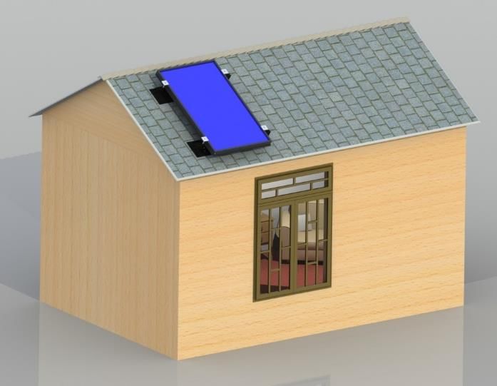
2. Roof mounting

Roof mounting is uncommon and comes with concerns of the heater glass being frequently soiled due to
its mounting angle and difficulty in reaching it for regular cleaning, and concerns with water leakage
through the ducting roof penetrations. We recommend roof mounts be completed by a licensed HVAC
or roofing contractor to ensure best practice during the mounting and routing of ducting. Roof
mounting can also use commercially available PV (photovoltaic) solar mounting rails and hardware if
desired.

3. Mounting on an exterior plenum / frame construction

Some users of the product elect to mount the heaters to a custom exterior plenum or framing
commonly made from wood or other construction materials. We recommend mounting the panels at a
tilt angle ideal for your latitude solar in the winter, which can be determined from a calculator such as
this one: http://www.solarelectricityhandbook.com/solar-angle-calculator.html

  Copyright 2021, Arctica Solar. All Rights Reserved                                                19
Section 5.0 – Mounting and connection of the 10W solar panel
The heater is provided with a lightweight 10W PV panel with a DC MALE power out and 4x corner
mounting gromet holes. The solar panel is provided with 4x wood lathe bolts and 8x plastic stand offs.
2x stand-offs should be behind each of the 4x mounting grommets on the solar panel. This provides a
0.5” stand-off for the solar panel from the wall which is needed to protect the electrical box on rear of
the solar panel from contact with the installation wall.

When mounting the solar panel, be careful not to place the solar panel in an area where it will be
shaded by the heater panel or other features of the install location, such as a roof overhang, nearby
vegetation, ect. Any shading of the solar panel during the day will cause the heater fan to lose power
and stop circulating heat.

Be sure to remove the protective plastic cover from the solar panel prior to operation. Connect the
MALE power plug from the solar panel to the FEMALE fan power lead at the base of the heater. We
recommend securing this joint with electrical tape or duct tape. Secure and route the PV panel wire
against the installation wall as needed.

Power to the heater can also be provided with a 12V AC to DC wall plug, which has a similar 5.5mm x 2.5
mm MALE power out as the provided solar panel, or another means of 12V DC power such as a battery.

  Copyright 2021, Arctica Solar. All Rights Reserved                                                 20
Section 6.0 – Interior vent covers and intake air filtration
The heater is provided with a small, washable intake air filter which we recommend placing downflow of
the intake collar, as seen below. This filter can be placed behind the interior intake vent collar for ease
of access during the heater’s lifetime. We recommend washing the filter every 3 months to ensure a
flow of clean air into the heater. Not filtering the air prior to intake into the heater may lead to
excessive fouling of the interior of the heater which may require a physical removal of the glass and
deep interior cleaning.

Different indoor intake and exhaust grill options exist at local big box hardware stores and online
retailers. New filter material such as is shown below can also be purchased at local and online retailers
as well as directly from Arctica Solar.

  Copyright 2021, Arctica Solar. All Rights Reserved                                                 21
Section 7.0 – Connection to the Heat-Only Thermostat
The 1500 heater has the option to be controlled by a heat-only thermostat provided with the heater.
The intake collar wire harness includes a 12’ wire pair which connects to the heat-only thermostat.
Unravel the thermostat wire and route it through the wall(s) as necessary into the living / heated space.
Cut to length and re-strip the wire ends if needed.

Route the wire through the back of the thermostat backplate. Connect one wire to terminal RH.
Connect the other to terminal W. The color of the wire to each terminal does not matter. Mount the
thermostat backplate to the wall and reattach the front plate with the provided batteries installed.

Set the thermostat to the desired room temp. The heater is activated by the thermal switch now
internal to the exhaust collar of the heater – Step 3.2.2. When the inside of the heater reaches above 30
C / 86 F the heater will activate and start delivering warm air into the living space if the desired
temperature is greater than the thermostat room temperature. Be careful to mount the thermostat a
suitable distance from the exhaust of the heater.

If you want the heater to run continuously whenever it is above 30 C AND there is enough sunlight on
the 10W solar panel to activate the fan, or do not want to use the thermostat, twist the red and black
leads from the thermostat wire together to short the circuit.

  Copyright 2021, Arctica Solar. All Rights Reserved                                                22
Section 8.0 – Heater lifetime care guide and suggestions
With proper maintenance, your 1500 Series Solar Air Heater should bring you years of free and
renewable supplemental space heating. Here are suggestions for caring for the heater over its lifetime.

8.1.    Washing intake air filter – every 3-6 months

With the heater installed, intake air should be filtered through the provided washable filter material.
This prevents buildup of dust and debris inside the heater which can reduce performance over time. We
recommend positioning the filter material between the intake grill and the ducting leading to the intake
/ fan collar and hand washing this material every 3-6 months.

8.2.    Cleaning of heater front glass – every 3-6 months or as needed

If the heater is mounted in the vertical wall position, it should not need frequent cleaning of the front
glass. But cleaning of the glass at regular intervals, like that of home windows, will increase lifetime
performance.

We recommend cleaning the front heater glass every 3 – 6 months while the heater is NOT in full
sunlight. Clean it during cloudy days, or at dawn or dusk to reduce stress on the glass and potentially
cause damage from rapid cooling.

Glass can be cleaned with Windex (or equivalent) and a lint-free rag or wipe, or with soapy water and
then wiped clean and dry. Or use a soft sponge to scrub the glass, clean water to rinse and a squeegee
and lint free towel to wipe dry.

8.3.    Preparing your heater for the Summer (off) Season – every 12 months

Care must be taken to set up your heater during the off season as to not cause unwanted heating even
with the thermostat off. Summer exposure will not damage the heater. We recommend the following
steps:

        8.3.1. Tape into place and seal off the gravity damper on the exhaust collar, or the exhaust
        ducting routed into the living space (see below). If left unsealed, naturally convective heat will
        bleed into the living space during the off season. We recommend taping the damper shut with
        duct tape or placing into the exhaust ducting a cut-to-size polyisocyanurate insulation “plug”
        which will choke any unwanted heat generation.

        8.3.2. If possible, cover the glass of the heater with an off-season cover such as a piece of
        cardboard / plywood / ect to prevent collection of sunlight onto the panel.

  Copyright 2021, Arctica Solar. All Rights Reserved                                                    23
8.4. Cleaning of heater ducting – every 12 months or as needed Periodically the indoor intake and exhaust grills should be removed from the ducting and a shop vacuum used to vacuum out any collected dust in the ducting. Clean ducting will ensure clean air circulation inside of the heater and reduce dust fowling of the absorber rear surface. In extreme soiling cases, the heater may need to be removed from the wall, intake and exhaust collars removed and vacuuming out of the interior of the heater itself with proper shop vacuum attachments or vacuum snake. The front of the absorber is sealed off from airflow, so it should not require removal and cleaning. If however the absorber becomes heavily soiled, the glass can be removed (See 8.6) and the absorber serviced or replaced. 8.5. Replacement of the air circulation fan – as needed If the air circulation fan dies during service, Arctica keeps in stock a supply of replacement fans for purchase. The user will have to access the intake fan collar and BEND UP the 2x plastic tabs to release the fan (red arrows below). The fan uses an 2 pin electronic clip to connect to the heater wire harness (right picture). Remove the defective fan by squeezing this clip. The new fan can be installed by following this instruction in reverse. Make sure to place the fan in such that the sticker on the fan is pointing INTO the heater, so that air will be drawn into the intake. 8.6. Removal and replacement of the heater front glass – as needed The heater is designed such that the absorber surface is not in the air exchange path to minimize soiling of the absorber surface and the air cavity between the absorber and the front cover glass during its lifetime. Therefore, during a normal heater lifetime the glass should never have to undergo a removal from the heater unit. However, if the glass is broken during service, or if the interior of the glass or absorber surface becomes soiled to the point of serious performance degradation, then removal of the glass for deep cleaning of the interior of the heater may be required. This is not a normal service item, but Arctica is providing guidance for removal of the heater glass in the case where it should be so necessary. Copyright 2021, Arctica Solar. All Rights Reserved 24
8.6.1. First, remove the heater from its installation position and place it on a flat work bench or table.
If the glass is broken, vacuum or remove any loose glass. The heater glass is tempered, so if it does
break it will shatter into many small pieces. Take care to avoid direct contact with the front absorber
surface as it is a delicate coating and will damage easily from physical contact.

8.6.2. Using a handheld drill and a drill bit of appropriate size, remove the rivet heads of each of the
surrounding rivets (shown with red arrows) holding the top rails to the heater body. There are 14x
rivets total on all 4x sides – 3x on short side, 4x on long. Carefully remove the long and short top rails
and save for re-installation later. Do not bend the rails to remove them.

8.6.4. In most cases the glass is adhered to the body of the heater with clear 100% silicone adhesive. If
the glass is NOT broken, use a box knife or razor knife to carefully cut the silicone seal between the glass
and the heater body on all sides of the glass, and carefully remove the glass with two people. If the
glass is broken use a hand scraper or razor to remove all broken glass and residual silicone adhesive. In
both cases use a razor scraper to remove as much of the existing silicone from the glass and the heater
body as possible.

  Copyright 2021, Arctica Solar. All Rights Reserved                                                   25
8.6.5. With the glass removed, DO NOT touch or rub the absorber surface to clean it. Blow is clean
with compressed air. If the absorber is damaged or dirty beyond use, you can order a new absorber
panel from Arctica Solar or remove the existing absorber panel and paint it black with “high heat black”
paint such as Rust-Oleum 248903.

8.6.6 If the glass is not broken and with all existing silicone removed to the greatest extent possible,
take this opportunity to thoroughly clean both sides of the glass with glass cleaner, or scrub clean and
squeegee and lint-free clothe wipe dry multiple times to ensure a crystal-clear glass surface prior to
glass re-install.

If the glass is broken, purchase a new piece of tempered glass sheet to these specifications. This should
cost around $100 - $130 USD.

8.6.7. From a local big box hardware store, get 1x tube of GE Silicone #1 adhesive, clear.

8.6.7. Using a caulking gun, place a bead of silicone around the perimeter of the heater on all 4x sides.
With two people, place the glass on top of the furnace frame, and the use 2-4x hand clamps per side to
hold the glass in place against the frame for no less than 24 hrs so the adhesive can fully cure.

  Copyright 2021, Arctica Solar. All Rights Reserved                                                 26
8.6.8. After 24 hrs, remove the hand clamps and place weather stripping or VHB tape along the edge
and outer perimeter of the glass. This provides protection for the glass against the reinstallation of the
aluminum top rails.

  Copyright 2021, Arctica Solar. All Rights Reserved                                                  27
8.6.9. Place the 4x top rails back into position over the glass and the furnace. Use hand clamps if
needed to re-align the holes with the existing rivet holes. Reconnect the rails with self-tapping stainless-
steel screws, #4, 3/8” length, 0.112” diameter (#4 screws size). If this screw size does not retain due to
the hole being too big in the heater body, use the next larger screw size.

8.6.10. Remount the heater per the original mounting instructions (Section 4.3). Take care to mount
the heater to a flat surface, not to overly bend, curve or deflect the heater during mounting. Doing so
may overly stress and break the glass. Careless installation is the number one cause of damage to the
heater during its lifetime!

  Copyright 2021, Arctica Solar. All Rights Reserved                                                  28
You can also read