NVIDIA Material Definition Language 1.1 - Technical
←
→
Page content transcription
If your browser does not render page correctly, please read the page content below

NVIDIA Material Definition Language 1.1
Technical Introduction

Document version 1.0
12 May 2014

                                          NVIDIA Advanced Rendering Center
                                                            Fasanenstraße 81
                                                                10623 Berlin
                                                     phone +49.30.315.99.70
                                                       fax +49.30.315.99.733
                                                      arc-office@nvidia.com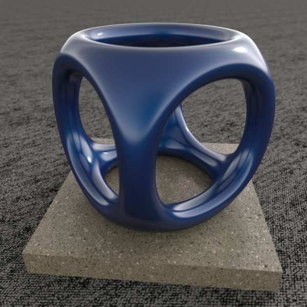
Copyright Information

© 1986, 2014 NVIDIA Corporation. All rights reserved.
This document is protected under copyright law. The contents of this document may not be translated, copied
or duplicated in any form, in whole or in part, without the express written permission of NVIDIA
Corporation.

The information contained in this document is subject to change without notice. NVIDIA Corporation and its
employees shall not be responsible for incidental or consequential damages resulting from the use of this
material or liable for technical or editorial omissions made herein.

NVIDIA, the NVIDIA logo, imatter, IndeX, Iray, mental images, mental ray, and RealityServer are trademarks
and/or registered trademarks of NVIDIA Corporation. Other product names mentioned in this document
may be trademarks or registered trademarks of their respective companies and are hereby acknowledged.

                                                                                 Document build number 219029

ii                                    MDL 1.1 — Introduction — 12 May 2014      ©   1986,2014 NVIDIA Corporation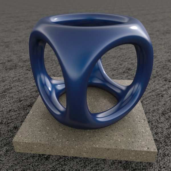
Contents
             1   Background . . . . . . . . . . . . . . . . . . . . . . . . . . . . . . . . . .      .   .   .   .   .   .   .   .   .   .   .   .   .   .   .   .   .   .   .   .   .   .    1
             2   Overview of key MDL features . . . . . . . . . . . . . . . . . . . .                .   .   .   .   .   .   .   .   .   .   .   .   .   .   .   .   .   .   .   .   .   .    1
             3   Comparing MDL to conventional shading languages . . . . .                           .   .   .   .   .   .   .   .   .   .   .   .   .   .   .   .   .   .   .   .   .   .    2
             4   MDL language elements for material libraries and re-use . . .                       .   .   .   .   .   .   .   .   .   .   .   .   .   .   .   .   .   .   .   .   .   .    3
             5   Materials . . . . . . . . . . . . . . . . . . . . . . . . . . . . . . . . . . . .   .   .   .   .   .   .   .   .   .   .   .   .   .   .   .   .   .   .   .   .   .   .    3
                   5.1 Elemental distribution functions . . . . . . . . . . . . . .                  .   .   .   .   .   .   .   .   .   .   .   .   .   .   .   .   .   .   .   .   .   .    4
                         5.1.1 Bidirectional scattering distribution functions                       .   .   .   .   .   .   .   .   .   .   .   .   .   .   .   .   .   .   .   .   .   .    4
                         5.1.2 Emissive distribution functions . . . . . . . . . .                   .   .   .   .   .   .   .   .   .   .   .   .   .   .   .   .   .   .   .   .   .   .    8
                         5.1.3 Volume distribution functions . . . . . . . . . . .                   .   .   .   .   .   .   .   .   .   .   .   .   .   .   .   .   .   .   .   .   .   .    9
                         5.1.4 Measured materials . . . . . . . . . . . . . . . . . .                .   .   .   .   .   .   .   .   .   .   .   .   .   .   .   .   .   .   .   .   .   .   11
                   5.2 Distribution function modifiers and combiners . . . .                         .   .   .   .   .   .   .   .   .   .   .   .   .   .   .   .   .   .   .   .   .   .   13
                   5.3 MDL syntax . . . . . . . . . . . . . . . . . . . . . . . . . . . .            .   .   .   .   .   .   .   .   .   .   .   .   .   .   .   .   .   .   .   .   .   .   16
             6   Modules . . . . . . . . . . . . . . . . . . . . . . . . . . . . . . . . . . . .     .   .   .   .   .   .   .   .   .   .   .   .   .   .   .   .   .   .   .   .   .   .   18
             7   Functions . . . . . . . . . . . . . . . . . . . . . . . . . . . . . . . . . . .     .   .   .   .   .   .   .   .   .   .   .   .   .   .   .   .   .   .   .   .   .   .   18
             8   Types . . . . . . . . . . . . . . . . . . . . . . . . . . . . . . . . . . . . . .   .   .   .   .   .   .   .   .   .   .   .   .   .   .   .   .   .   .   .   .   .   .   19
             9   Annotations . . . . . . . . . . . . . . . . . . . . . . . . . . . . . . . . . .     .   .   .   .   .   .   .   .   .   .   .   .   .   .   .   .   .   .   .   .   .   .   19

©   1986,2014 NVIDIA Corporation                   MDL 1.1 — Introduction — 12 May 2014                                                                                                      iii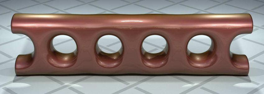
iv MDL 1.1 — Introduction — 12 May 2014 © 1986,2014 NVIDIA Corporation
1    Background
Renderers produce images from scene descriptions. A scene description consists of three-dimensional
geometric objects and their positioning in space. Common object representations describe objects by their
surface geometry, which sometimes only represent surfaces in space and sometimes represent volumetric
objects that are enclosed by the surface description.
Surfaces and volumes have material properties that determine how they interact with light and, ultimately, how
they are rendered in an image. Material properties range from the color of surfaces, to their reflection or
refraction properties, light emission of surfaces, scattering and absorption properties of volumes, and even to
additional geometric properties of surfaces, such as cut-outs, displacements, or bump maps, which are
commonly not modeled in the primary geometric description.
For greatest flexibility, rendering systems often use programming languages to describe material properties.
These can be general purpose languages, such as C, or domain specific languages, commonly referred to as
shading languages, since material authors can program how the actual shading of a surface is computed from
material parameters, incoming light, and more. Shader programmers can and do go to the extreme of writing
full renderers in shader programs. However, modern renderers can implement techniques such as multiple
importance sampling only if they understand the material properties. This analysis is difficult with traditional
shading languages, since they define the computation for the shading result itself and not just the material
properties. Material Definition Language (MDL) is a domain-specific programming language that can define
material properties to serve modern renderers in this sense.
This document gives you a functional overview of MDL. The next section provides a quick overview of key
features. The following sections provide more detail about those features.

2     Overview of key MDL features
MDL consists of two major parts:
    1 A declarative material definition based on a powerful material model, and
    2 A procedural programming language to define functions that can compute values for the parameters of
      the material model
The declarative material definition defines what to compute, not how to compute it, while the procedural
programming language preserves the infinite flexibility for creative material authors to define material
properties with their own programs.
Key features:
     MDL is independent of rendering algorithms. The declarative material definition interfaces with a

       renderer through the underlying material model, which is purely descriptive in terms of physical material
       properties and agnostic of any renderer algorithm.
     MDL supports the needs of modern rendering algorithms with a well-defined material model and

       enough material properties to support path tracing or multiple importance sampling.
     MDL is supported across a series of renderers developed by NVIDIA and it is designed to be extensible

       and adoptable by other renderers.
     Material definitions in MDL can be parameterized to enable flexible, custom-built domain-specific

       material libraries.
     MDL has a well-defined module and package concept to support packaging and distribution of material

       libraries.
     MDL supports the re-use and further customization of additional materials.

     MDL supports the customization of materials with predefined parameter sets, such that a material

       library for a certain material family can be based on one generic material and various parameter sets for
       specific instances of that material. When such a predefined parameter set is used, it can then still be

©   1986,2014 NVIDIA Corporation           MDL 1.1 — Introduction — 12 May 2014                                    1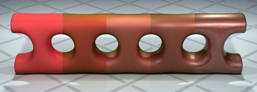
modified to further adjust the look of the material.
     The renderer state and the standard modules defined by MDL enable material authors to program a wide

      variety of functions to initialize material parameters, including procedural methods, noise-based
      textures, texture projection maps, and texture blend pipelines.
     MDL is designed for modern highly-parallel machine architectures. The procedural language only

      allows the definition of pure functions that have access to rendering state and that are free of side effects
      and global dependencies. These functions can therefore be scheduled and executed depending on the
      needs of the renderer and machine architecture.
Although it emphasizes physically plausible materials, MDL supports traditional computer graphics
techniques that are important in conventional rendering and modeling workflows. A MDL material is, in
general, applied to a surface and consists of the following properties:
     Surface properties that describe the bidirectional scattering distribution function (BSDF) for reflective

      and transmissive properties, the emissive distribution function (EDF) for emissive properties and the
      radiant exitance for the amount of emission.
     A Boolean flag that specifies whether the surface encloses a volume, and thereby defines if the volume

      properties apply to the enclosed volume or should be ignored.
     Additional surface properties that can be used to define the back-side material for surfaces that do not

      enclose a volume.
     Volume properties that describe the scattering and absorption coefficients and the volume distribution

      function (VDF), also known as the volume phase function.
     Geometric properties that describe cut-outs, displacement mapping, and normal mapping.

     BSDF properties that are set to values composed from a fixed set of elemental BSDFs and operators on

      them. These operators can be modifiers for tinting or thin-film effect, or they can be combinators for a
      weighted mix or layering of BSDFs including Fresnel effects. The layering operator supports an
      additional normal mapping effect local to the top image. These combinators make this a very flexible
      material model.
     EDF and VDF properties can be composed similar to BSDFs.


3    Comparing MDL to conventional shading languages
The use of conventional shading languages can be roughly categorized as follows:
    1 They are used to implement functions to describe the spatial distribution of material features — texture
      lookups, procedural textures, and projections.
    2 They are used to provide re-usable building blocks, called shaders, that describe materials with
      parameters that correspond to material properties, such as the reflective, emissive and transmissive
      behavior of an object.
    3 They are used to implement the computations needed in shaders, such as light-material interactions or
      other algorithmic extensions of the renderer. Shaders may even implement full-scale rendering
      computations, such as volume renderers, particle renderers or complete global illumination solutions.
While these areas are typically used by different audiences and require different user skills, traditional shading
languages do not explicitly distinguish between these use cases. MDL clearly separates those domains to
address the specific needs of the different audiences.
In the three numbered areas above, the first corresponds to what MDL offers with its procedural language for
implementing functions. The second area corresponds to what MDL offers with its material definition and
rich, highly configurable material model. The third area has no correspondence in MDL and is seen as the
domain of the renderer.

2                                        MDL 1.1 — Introduction — 12 May 2014          ©   1986,2014 NVIDIA Corporation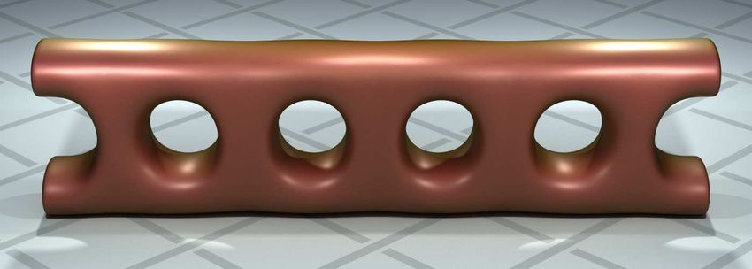
4     MDL language elements for material libraries and re-use
Functions, materials with their components, and modules are the main language elements that MDL offers for
material libraries and re-use.
Functions can be used individually for the parameters of a renderer, for example, the environment color, or to
provide values for material parameters such as a texture lookup for a color parameter for a material. Functions
can also provide a mechanism for code re-use and data hiding by encapsulating other functions. The
encapsulated functions can be provided with explicit parameter values within the body of the encapsulating
function. The resulting function can implemented as a complex calculation with a simpler signature that
provides control only for those parameters significant for the intended effect.
Materials and their BSDF, EDF, and VDF properties are the main building blocks in MDL. They can be passed
to other materials as parameters, which allows the development of generic materials that re-use aspects of a
material and extend or change other aspects. For example, a new material could be based on a generic material
that takes another material as input and changes it to a thin-walled material by applying the surface properties
of the other material on both sides of the surface.
A material definition can define input parameters that can be used within the material in expressions and
function call parameters to initialize properties of the material model or of other already existing materials.
Parameterizing a material definition enables the encapsulation and customization of materials to create custom
material libraries.
MDL supports the customization of materials with predefined parameter sets, so that a material library for a
certain material family can be based on one generic material and various parameter sets for specific instances of
that material. When such a predefined parameter set is used, it can then still be modified to further adjust the
appearance of the material. For example, a general metal material can be used with a family of parameter sets to
offer a material library of different gold and silver alloys. A user can pick a specific material from the library
but still modify the final color.
All files in MDL are defined to be modules. They define a namespace and shield identifiers from name clashes,
which is useful if material libraries are deployed and used together with other libraries or further in-house
material developments. Modules can contain materials, functions, and related types and constants.

5     Materials
MDL provides a purely declarative syntax for describing the interaction of an object with light. It relies on
predefined building blocks that can be efficiently implemented in a modern renderer, yet are powerful enough
to describe a large majority of real-world materials. The renderer-side interface of the material, the material
model, is represented by a MDL built-in structure-like type, which contains the different properties of the
material:

    struct material {
        uniform bool          thin_walled   =   false;
        material_surface      surface       =   material_surface();
        material_surface      backface      =   material_surface();
        uniform color         ior           =   color(1.0);
        material_volume       volume        =   material_volume();
        material_geometry     geometry      =   material_geometry();
    };

©   1986,2014 NVIDIA Corporation            MDL 1.1 — Introduction — 12 May 2014                                 3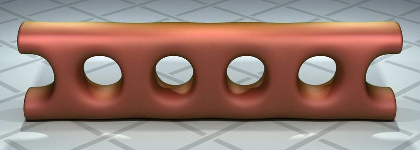
Depending on the building blocks used, three different kinds of materials can be distinguished:
      1 Regular materials describing a surface that separates one volume from another
      2 Thin-walled materials where the geometry only describes a soap-bubble like shell
      3 Two-sided materials which also have the thin-walled property, but interact differently with light hitting
        the geometry from the back side
The surface, emission, volume, and geometry aspects are also defined by built-in structure-like types:

    struct material_surface {
        bsdf              scattering = bsdf();
        material_emission emission   = material_emission();
    };

    struct material_emission {
        edf               emission        = edf();
        color             intensity       = color(0.0);
        intensity_mode    mode            = intensity_radiant_exitance;
    };

    struct material_volume {
        vdf   scattering             = vdf();
        color absorption_coefficient = 0.0;
        color scattering_coefficient = 0.0;
    };

    struct material_geometry {
        float3        displacement   = float3(0.0);
        float         cutout_opacity = 1.0;
        float3        normal         = state::normal();
    };

5.1     Elemental distribution functions
To describe the interaction with light, MDL provides a set of elemental distribution functions. The names of
the distribution functions end with one of three suffixes:

bsdf
        Describes the interaction of the light with the surface
edf
        Describes the emissive properties of the surface
vdf
        Describes the light distribution in the volume

The elemental distribution functions are used as components of materials. The following three sections use
these functions in minimal materials to demonstrate their visual properties.

5.1.1    Bidirectional scattering distribution functions
The elemental BSDFs define the action of light at the surface of an object: how it is reflected from the surface
and transmitted through the surface.

4                                          MDL 1.1 — Introduction — 12 May 2014       ©   1986,2014 NVIDIA Corporation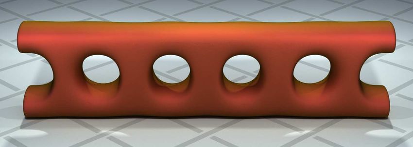
diffuse reflection bsdf
                                                               A colored diffuse reflection component using
                                                               roughness based on the Oren-Nayar model.
                                                               This BSDF also implements pure Lambertian
                                                               reflection.

                                                               diffuse transmission bsdf
                                                               A colored diffuse Lambertian transmission
                                                               component.

©   1986,2014 NVIDIA Corporation   MDL 1.1 — Introduction — 12 May 2014                                       5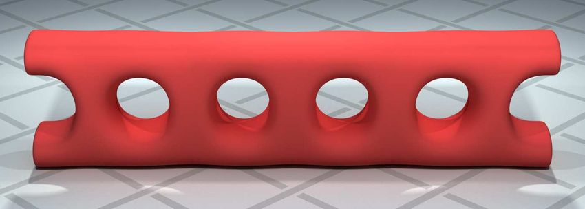
specular bsdf
                                A component representing colored specular
                                reflection, specular transmission (refraction) or
                                a combination of both. This image
                                demonstrates pure specular reflection.

                                specular bsdf
                                The use of the specular bsdf in this image
                                demonstrates pure specular transmission. The
                                index of refraction is controlled as a parameter
                                to the BSDF.

6   MDL 1.1 — Introduction — 12 May 2014           ©   1986,2014 NVIDIA Corporation
specular bsdf
This image combines both the reflective and
transmissive factors of specular bsdf. If
transmission and reflection are enabled at the
same time, they are combined using a Fresnel
term based on the index of refraction specified
for the volume. This image also demonstrates
how the color parameter of a distribution
function can scale the function’s result.
simple glossy bsdf
A component representing colored glossy
reflection, glossy transmission or a combination
of both. As in the specular case, if transmission
and reflection are enabled at the same time, they
are combined using the Fresnel term.
© 1986,2014 NVIDIA Corporation MDL 1.1 — Introduction — 12 May 2014 7backscattering glossy reflection bsdf
A colored glossy-reflection component capable
of simulating back-scattering of light.
5.1.2 Emissive distribution functions
MDL defines a set of elemental emission distribution functions to simulate the light that interacts with MDL’s
surface and volume definitions. The traditional computer graphics methods of lighting a scene with special
purpose constructs (like "directional lights" and "point lights") is replaced in MDL by defining properties of
geometric objects so that they emit light. In this way, the syntactic expression of lighting is unified with the
expression of surface and volume appearance. As geometric objects, "lights" in MDL are also more readily
integrated into the scene definition interface of 3D applications.
diffuse edf
Light emitted in all directions from the surface
of the object, called Lambertian light
distribution by analogy to Lambertian diffuse
reflection. The spherical geometric object
defined with the emissive material is visible in
the image, but without the typical perceptual or
photograph effects that provide "bloom" or
lens distortions.
8 MDL 1.1 — Introduction — 12 May 2014 © 1986,2014 NVIDIA Corporationspot edf
Distribution of the emission based on the
cosine between emission direction and surface
normal (exponential cosine distribution). The
emissive object is visible as a dark gray sphere
because the camera is located at the edge of the
cone of light distribution.
measured edf
Light distribution based on a measured light
profile. Arbitrary geometric structure for light
distribution from the emissive object can be
specified based on standard industrial formats
called light profiles. Here the sharper boundary
of the spatial distribution of light energy allows
the light reflected by the diffuse surface of the
object to be seen as a reddish color in the
shadowed area.
5.1.3 Volume distribution functions
BSDFs define the action of light at the object’s surface. Volume distribution functions (VDFs) specify the
behavior of light within an object. In combination, they provide for all the possibilities of light reflection,
transmission, and interior modulation for lighting simulation.
© 1986,2014 NVIDIA Corporation MDL 1.1 — Introduction — 12 May 2014 9anisotropic vdf
Addition of absorption effects and subsurface
scattering to the material’s volume. The BSDF
for this material specifies that all light penetrates
the object (transmission scattering mode).
anisotropic vdf
Parametric control of the volume distribution
function can simulate a wide variety of physical
substances. The material of this image only
differs from the material of the previous image
in the BSDF specifying both reflection and
transmission of the light, and in the values of
three VDF parameters that define the index of
refraction, the degree of scattering, and the
scattering direction within the object.
10 MDL 1.1 — Introduction — 12 May 2014 © 1986,2014 NVIDIA Corporationanisotropic vdf
Even with apparently simple materials made
from the elemental bsdfs, the design of the
lighting simulation can reveal complex
properties of the material. Here the material of
the object, anisotropic vdf, is identical to
the previous example, lit by the emmisive
distribution function measured edf of the
previous section.
5.1.4 Measured materials
The previous definitions of light transport used analytic methods which depend upon a mathematical theory of
the physics of light. MDL also supports material definitions based on measurement of real-world surfaces,
where light interaction with objects is measured over a series of different incident light and viewing angles. The
resulting dataset is used as input to an elemental BSDF in MDL that defines a measured BSDF.
A measurement dataset can be used as an MDL input parameter by constructing a value of type
bsdf measurement. The bsdf measurement constructor takes a file path of a measurement dataset as an input
argument:
bsdf_measurement(uniform string name)
A value of bsdf measurement is used as the argument for the measurement parameter of the BSDF
measured bsdf:
bsdf measured_bsdf(
uniform bsdf_measurement measurement,
uniform float multiplier = 1.0,
uniform scatter_mode mode = scatter_reflect,
uniform string handle = ""
);
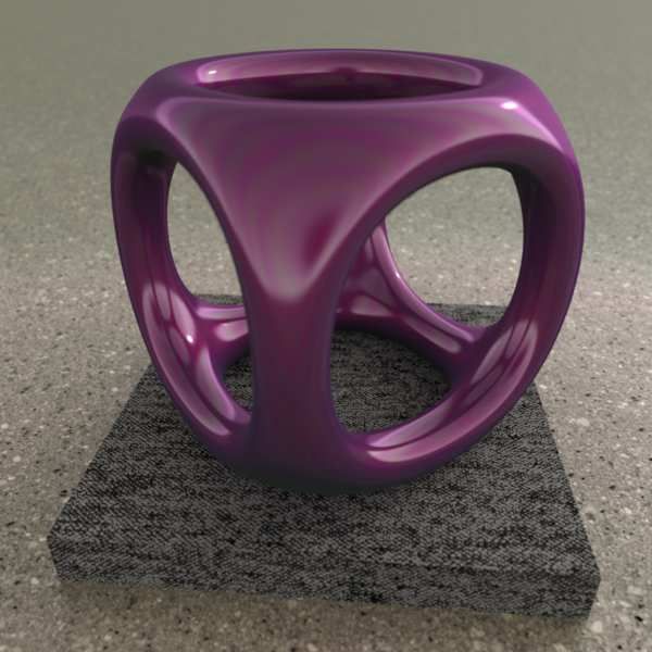
© 1986,2014 NVIDIA Corporation MDL 1.1 — Introduction — 12 May 2014 11measured bsdf
The red material is defined by a measurement of
a car paint surface. The materials of the pedestal
and ground are defined by measurements of
carpet and cement, respectively. Accompanying
texture maps supply the level of fine color
detail for the carpet and cement.
measured bsdf
In this image the pedestal and ground materials
have been exchanged. The geometric models
define a parametric space for the texture
mapping, which is combined with scaling
factors for the texture application provided by
the material. The blue car paint here uses the
same material as the previous example, with a
different measured data set provided as the
value of the name parameter to
bsdf measurement.
12 MDL 1.1 — Introduction — 12 May 2014 © 1986,2014 NVIDIA Corporation5.2 Distribution function modifiers and combiners
The previous sections showed simple materials built from the elemental distribution functions based on
analytic methods and real-world measurements. MDL also provides building blocks to combine or modify
BSDFs to enable the description of more complex light-material interactions. The elemental EDFs can also be
mixed together to implement combined emission properties in a single material.
Distribution function modifiers and combiners can describe complex reflective and transmissive characteristics
(compound distribution functions). Because of their uniform syntax, analytic and measured materials can also
be combined. Modifiers can be applied recursively, allowing further modification and combination of
compounds.
normalized mix
Mix N elemental or compound distribution functions based on N float weights. If the sum of the
weights exceeds 1, they are normalized.
clamped mix
Mix N elemental or compound distribution functions based on N float weights. Distribution functions
and weights are summed in the order they are given. When the sum of weights reaches 1, the remainder,
if any, is clamped.
weighted layer
Add an elemental or compound BSDF as a layer on top of another elemental or compound BSDF
according to a weight w. The base is weighted with 1-w.
fresnel layer
Add an elemental or compound BSDF as a layer on top of another elemental or compound BSDF
according to a weight w and a Fresnel term using a dedicated index of refraction for the layer. The base is
weighted with 1-(w*fresnel(ior)).
custom curve layer
Add an elemental or compound BSDF as a layer on top of another elemental or compound BSDF
according to a weight w and a Schlick-style directional-dependent curve function. The base is weighted
with 1-(w*curve()).
measured curve layer
Add an elemental or compound BSDF as a layer on top of another elemental or compound BSDF
according to a weight w and a directional-dependent measurement of the reflection behavior. The base is
weighted with 1-(w*measurement()).
tint
Tint the result of an elemental or compound distribution function with an additional color.
thin film
Add reflective thin film interference color to an elemental or compound BSDF.
directional factor
A direction-dependent weight based on a custom curve that is applied to one elemental or compound
BSDF.
measured curve factor
A direction-dependent weight based on a measured reflection curve that is applied to one elemental or
compound BSDF.
The following series demonstrates the sequential combination of a series of BSDFs. Each successive image
adds a new layer to the previous one.
© 1986,2014 NVIDIA Corporation MDL 1.1 — Introduction — 12 May 2014 13The base layer is defined by diffuse reflection bsdf with a tinting color of red.
A yellow-tinted diffuse reflection bsdf is added to the edges with custom curve layer.
A layer of simple glossy bsdf is added using weighted layer.
14 MDL 1.1 — Introduction — 12 May 2014 © 1986,2014 NVIDIA CorporationAnother layer of simple glossy bsdf with sharper highlights is added with weighted layer.
Adding a layer of specular bsdf with fresnel layer resembles the clear coat of an automotive finish.
Analytic and measured materials can also be combined. Measurement devices for light scattering may have
difficulty accurately recording intensities at extreme grazing angles. For example, the measured car paint
renderings on page 12 lack the glossy reflections that are typical at edges. Defining this reflection as a layer to
be combined with the measured BSDF can produce the missing effect.
Only using measurement data Adding edge reflection as a layer
© 1986,2014 NVIDIA Corporation MDL 1.1 — Introduction — 12 May 2014 155.3 MDL syntax
MDL provides a notation inspired by functional programming to create a custom material struct and then map
an input parameter set to this material. The following example describes a simple material exhibiting
Lambertian reflective properties and an input providing a diffuse color input defaulting to red:
material diffuse(color diffuse_color = color(0.7,0.0,0.0) )
= material(
surface : material_surface(
scattering : diffuse_reflection_bsdf(
tint : diffuse_color
)
)
);
Note here that MDL structs can have defaults for their members and that the example only provides a value for
the surface member of the material. All other members of the material struct maintain their default values.
A similar syntax can be used to change the parameterization or interface of an already existing material. The
following example code creates a blue variant of the preceding example:
material blue_diffuse()
= diffuse(
diffuse_color: color(0.0,0.0,0.7)
);
A parameter of a material can be a material itself. Since a material functions as a struct, this permits the
straightforward reuse of materials. For example, the following material takes an arbitrary base material and
adds a reflective clear coat on top:
material add_clear_coat(color ior = color(1.5), material base)
= material(
volume : base.volume,
geometry : base.geometry,
surface : material_surface (
emission : base.surface.emission,
scattering : fresnel_layer(
layer : specular_bsdf(
scatter_mode : scatter_reflect
),
base : base.surface.scattering,
ior : ior
)
)
);
Measured materials are also defined in a syntactically consistent way in the material definition. The following
material defines the measured blue car paint that is combined with a glossy reflection layer, shown on page 15.
Note that the measured data is provided as a filename parameter of function bsdf measurement.
16 MDL 1.1 — Introduction — 12 May 2014 © 1986,2014 NVIDIA Corporationmaterial carpaint_blue(float coat_ior = 1.5)
= material (
surface : material_surface (
scattering : fresnel_layer(
layer : specular_bsdf(
mode : scatter_reflect,
tint : color(1.0)),
base : measured_bsdf(
measurement : bsdf_measurement(
"carpaint_blue.mbsdf"
)
),
ior : coat_ior
)
)
);
MDL provides a let expression to support the introduction of local variables. The content of the expression is
purely declarative, but declarations are evaluated in sequence, allowing access to already declared variables in
later declarations. Using a let expression, the add clear coat example could be rewritten as:
material add_clear_coat(color ior = color(1.5), material base)
= let {
bsdf coat
= specular_bsdf(
scatter_mode : scatter_reflect
);
bsdf coated_scattering
= fresnel_layer(
layer : coat,
base : base.surface.scattering,
ior : ior
);
material_surface coated_surface(
emission : base.surface.emission,
scattering : coated_scattering
);
} in
material(
volume : base.volume,
geometry : base.geometry,
surface : coated_surface
);
Using let expressions, libraries of materials can be based on a set of small, self-defined, reusable building
blocks. For example, putting a layer of rust on the surface of a painted car can be implemented as the
combination of two materials.
© 1986,2014 NVIDIA Corporation MDL 1.1 — Introduction — 12 May 2014 17material rusty_carpaint( /* ... */ )
= let {
material base = carpaint_material();
material top = rust_material();
float blend = rust_blend_function();
} in
material(
surface : material_surface(
scattering : weighted_layer(
layer : top.surface.scattering,
base : base.surface.scattering,
weight : blend
)
/* ... */
)
);
6 Modules
Modules allow materials and functions to be packaged for re-use in independent libraries that can be used
together. Name conflicts can be avoided by choosing between unqualified and qualified in module import
statements.
MDL’s import mechanisms does not offer any name-conflict resolution mechanisms. The purpose of this
policy is to have a well-defined module system to enable packaging and re-use of material libraries by
independent providers.
A directory is considered a package. The name of the package is the name of the directory. Note that this
restricts the names of directories that are used as packages to legal identifiers.
Modules can be contained in packages and the resulting packages can be nested, allowing comprehensive
organization of complex libraries.
Extensions to core MDL, such as standard annotations and distribution, math, texture and noise functions are
provided in the form of standard modules.
7 Functions
Users needing special texturing functionality are able to provide their own texturing functions written in a C-
inspired procedural language. Using this language, implementation of procedural textures is possible as well as
the implementation of custom uv-coordinate handling and generation. Texturing functions have access to a
limited, read-only rendering state dedicated to the needs of texturing. Texturing functions are pure and free of
side-effects. Together with the dedicated texturing state, this makes texturing functions independent from the
renderer architecture, making it easier to use them in multiple renderers.
Function argument initialization can use other function calls, forming a call graph that is the equivalent to
shader graphs which are often provided by traditional shading languages.
MDL supports specification of default values for function parameters and a calling syntax using named
arguments to provide convenience when using texturing functions.
The following is an example of a function with default initializers:
18 MDL 1.1 — Introduction — 12 May 2014 © 1986,2014 NVIDIA Corporationfloat3 texture_lookup(float2 uv, int space = 0);
Calling function texture lookup in another function body might be expressed as follows:
float3 c = texture_lookup(uv: coord);
8 Types
The type system of MDL is also inspired by the C language, with additional custom types for domain-specific
use, such as vectors and matrices. MDL also provides an abstract type for colors, allowing renderers to choose
their own, appropriate format for storing color information.
The struct type plays a major role in MDL’s material definition syntax. To allow convenient handling of
materials, struct types have an automatic constructor which, together with the default values for struct
members and the extended calling syntax for functions, allows the relevant code to be short and precise.
Variables of an array type can be declared in two ways in MDL. The declarations differ in how the size of the
array is specified.
In the size-immediate array type, the size of the array is given as a constant value when the array variable
is declared. This array type corresponds to the conventional array type in the C language.
In the size-deferred array type, the size of the array is given as a symbolic size identifier and bound to a
real size on first use. The size identifier can be used when the size of its array is required in other
expressions.
9 Annotations
MDL defines a mechanism called annotations to associate meta-data with material definitions and their
components.
Annotations can be applied to:
Functions
Function input parameters
Function return values
Struct members
Enumeration values
Material definitions
Material definition input parameters
Annotations are a standard mechanism for adding additional semantic information, such as graphical interface
specification, documentation data and other integration support, to a program. MDL provides a set of
standard annotations (defined in a standard MDL module) as well as a syntax for users to add custom
annotations. Syntactically, MDL annotations are inspired by the syntax of C# annotations.
© 1986,2014 NVIDIA Corporation MDL 1.1 — Introduction — 12 May 2014 19You can also read