Advanced Technologies for Blast Furnace Life Extension - Nippon Steel
←
→
Page content transcription
If your browser does not render page correctly, please read the page content below
NIPPON STEEL TECHNICAL REPORT No. 123 March 2020

                                                                                                                                    UDC 669 . 162 . 27 . 012
    Technical Report

       Advanced Technologies for Blast Furnace Life Extension
                                                                                                           Kaoru NAKANO*             Yutaka UJISAWA
                                                                                                           Takanobu INADA            Atsuhiro OBOSO
                                                                                                           Kenji KATAYAMA

               Abstract
                  Since blast furnace is a core process of steel mills, blast furnace repair requires a long re-
               pair period after blow-out and a large amount of money, which has a great impact on manage-
               ment. Extending blast furnace lives has been a major issue in order to provide more freedom
               in business decisions. On the other hand, mathematical blast furnace models, which have
               been developed since the 1970s, have improved prediction accuracy by repeating operation
               designs and analyses with data obtained over many years and extended these functions includ-
               ing analyses of the stress field in a blast furnace and erosion of hearth refractories. This paper
               outlines the mathematical blast furnace models and describes the technologies for blast fur-
               nace life extension and these applications to the next blast furnace designs.

1. Introduction                                                                       Thus, owing to the enhanced accuracies and the sophisticated
    The blast furnace is a core process in steel works and is crucial             functions of the blast furnace mathematical models thus far devel-
equipment in determining the scale of the business operation of steel             oped, the blast furnace mathematical models are now being applied
works. Blast furnace repair requires a long repair period after the               not only to the conventional blast furnace design parameters, but
blow-out and a large amount of money, and therefore, imposes a                    also to a wider range covering the BF emptying operation design for
great load on management. The extension of the blast furnace life,                stave cooler exchange and hearth refractory protection operation de-
which was about 5–10 years in the early 1970s, was a crucial issue                sign. As a result thereof, the Wakayama No. 4 Blast Furnace which
in providing greater freedom in making business decisions.                        was designed for an operation life of seven years and was blown-in
    The instrumentational information to grasp the in-furnace states              in 1982 was blown-out in July 2009, establishing the then world re-
is highly limited. Therefore, since the 1970s, Nippon Steel Corpora-              cord of twenty-seven years and four months of continuous opera-
tion has developed blast furnace mathematical models to predict and               tion. Furthermore, the Wakayama No. 5 Blast Furnace which was
analyze the phenomena in a blast furnace, and to give appropriate                 blown-in in February 1988 achieved the world record of thirty years
values to operation parameters for operation guidance (such guid-                 and eleven months of continuous operation when it was blown-out
ance being hereinafter referred to as operation design). During the               in January 2019.
process of the development, the prediction accuracy has been im-                      In the meantime, the furnace shape and the hearth structure of
proved by repeating the prediction, operation design and the opera-               the next generation blast furnace used to be designed based on the
tion analysis regarding the phenomena in a blast furnace by using                 empirical information. However, the blast furnace mathematical
the blast furnace mathematical models, corresponding to the                       models, the functions of which have been sophisticated by interact-
changes in the operation conditions such as the increased ratio of                ing with the actual blast furnace data during the development of the
pulverized coal injection and oxygen-enriched blasting. Further-                  blast furnace life extension technologies, are now being applied.
more, along with the improvement in the numerical computation ca-                 The currently operated Blast Furnaces of the Kokura No. 2 with a
pability, the blast furnace mathematical models became 3D from                    furnace volume of 2 150 m3, the Kashima No. 1 and No. 3 with a
1D, and the function was further sophisticated to cope with not only              furnace volume of 5 370 m3 and the Wakayama No. 1 and No. 2
the phenomena of fluidity, heat transmission and reaction, but also               with a furnace volume of 3700 m3 were designed from the theoreti-
the analyses of the stress of the BF packed bed and the hearth re-                cal viewpoint. All these blast furnaces are designed for a life span of
fractory erosion.                                                                 twenty-five years or longer from blow-in.

*     Chief Researcher, Ironmaking Research Lab., Process Research Laboratories
      20-1 Shintomi, Futtsu City, Chiba Pref. 293-8511

                                                                        - 109 -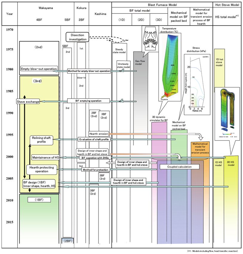
NIPPON STEEL TECHNICAL REPORT No. 123 March 2020

    This article outlines the blast furnace mathematical models, and              by our own company were completed. Furthermore, to cope with
describes the development of the blast furnace life extension tech-               the in-furnace non-steady states in a production blast furnace opera-
nologies, the blast furnace shape design and the hearth structure de-             tion, non-steady blast furnace mathematical models were developed
sign by using the blast furnace mathematical models.                              solely by our own company. In 1987, for the planning and the exe-
                                                                                  cution of the non-steady operation for the stave cooler exchange,
2. Progress of Research and Development                                           one-dimensional non-steady blast furnace mathematical models
    The progress of the research and development is shown in Fig. 1.              were utilized. Thereafter, the blast furnace operation simulation
The development of the blast furnace mathematical models was                      models were used for such purposes as operation efficiency im-
started in the early 1970s, and in 1974, the blast furnace mathemati-             provement and hearth refractory protection, and at the same time,
cal models (one-dimensional steady model) exclusively developed                   their accuracy and practicability were enhanced through the interac-

                        Fig. 1 Progress of technologies for blast furnace life extension and mathematical blast furnace model

                                                                        - 110 -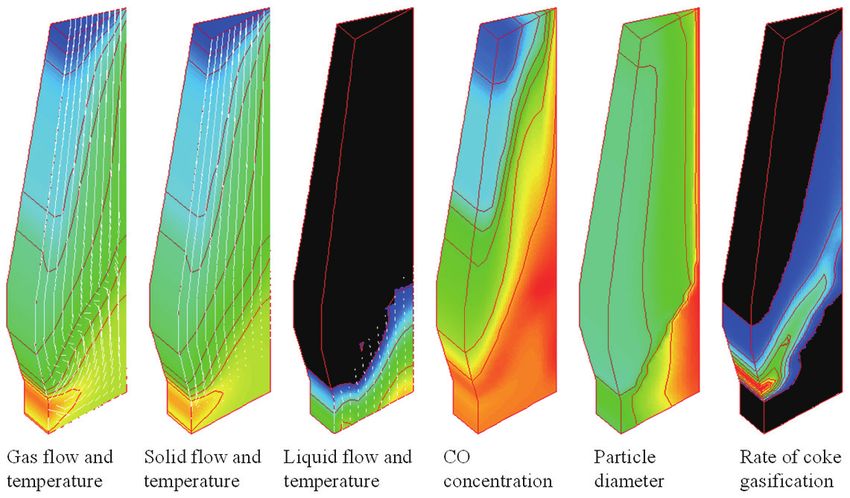
NIPPON STEEL TECHNICAL REPORT No. 123 March 2020
tion with the diverse actual operation data. Such simulation models have been advanced to the level where they can provide guidelines
were advanced to the 3D non-steady blast furnace mathematical for the designs of the shape of a blast furnace with high operation
models (hereinafter referred to as the “3D dynamic simulator for efficiency and high stability, and the hearth structure having a high
BF”) that are capable of estimating the in-furnace distribution state resistance to the hearth refractory erosion.
in the directions of height, radius and circumference.
In addition, in order to evaluate the stability of the in-furnace 3. Development of Blast Furnace Mathematical
material flow, which was impossible by the conventional technolo- Models
gies, the BF packed bed stress field estimation model (hereinafter In Fig. 2, the phenomena in a blast furnace and the developed
referred to as the “Mechanical model on BF packed bed”) was com- blast furnace models are shown. In these models, the estimation
pleted in 1995, which is the first of its kind in the world that can es- method of the reaction rate, and the setting of correct numerical val-
timate the burden descend and the stress distribution of the burden ues for the parameters such as the characteristic values of heat and
by assuming the BF packed bed as an elastic-plastic body. With the material transitions that govern the accuracies of the theoretical esti-
development of such varied mathematical models, the unrecogniz- mation when using mathematical models are crucial in determining
able in-furnace state of a blast furnace that is considered to be a the practical usability value of the models. Therefore, in these mod-
huge black-box-like reactor vessel has been quantified, and the els, incessant development and improvement efforts have been
quantitative estimations of the non-steady operation required for the made for a long period of time based not only on laboratory base
equipment maintenance represented by the stave cooler exchange experiments, but also by comparing and verifying the model data
and the operating condition that suppresses the erosion of the hearth with the measured data obtained from actually operating blast fur-
refractories have been realized. naces. Key models that play important roles in the blast furnace life
Furthermore, by the integrated use of the 3D dynamic simulator extension technologies are outlined hereunder.
for BF, the Mechanical model on the BF packed bed, and the hearth 3.1 3D dynamic simulator for BF
molten pig iron (molten pig being hereinafter referred to as hot met- As shown in Fig. 3, the 3D dynamic simulator for BF 1) is the
al) flow and hearth refractory erosion estimation models (hereinafter model that enables the 3D recognition of the moment by moment
referred to as the “Mathematical model for the transient erosion non-steadily changing compositions, temperature distributions and
process of the BF hearth”), the blast furnace mathematical models the states of flow in the gaseous, liquid and solid phases. The blast
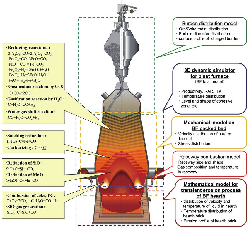
Fig. 2 Phenomena in blast furnace and mathematical models
- 111 -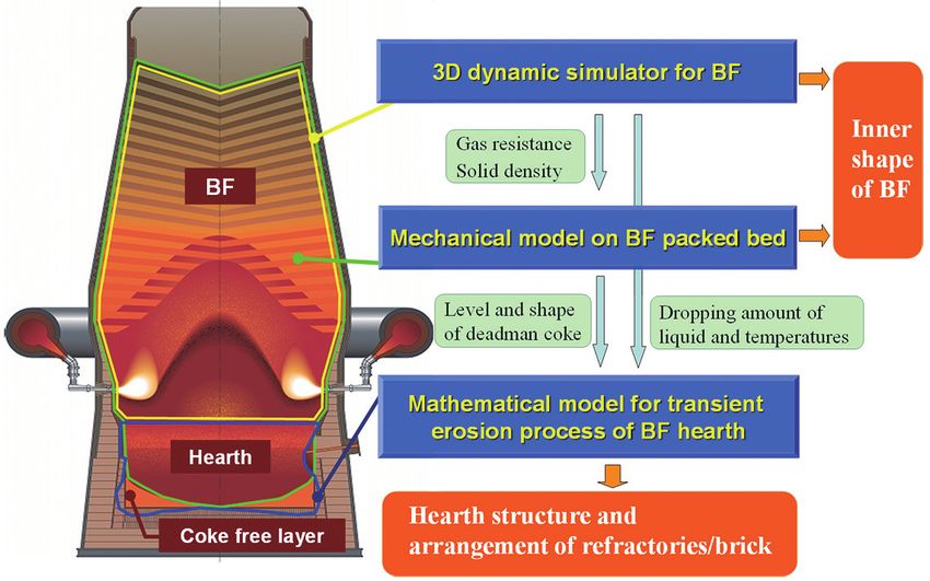
NIPPON STEEL TECHNICAL REPORT No. 123 March 2020

furnace inner space is divided into minute regions. In each minute                    distribution and so forth) and the boundary condition (charged bur-
region, simultaneous partial differential equations consisting of bal-                den distribution, blasting condition) to the blast furnace mathemati-
ance equations with respect to material, energy and momentum in                       cal models.
the gaseous, liquid and three solid phases are developed, and solved                  3.2 Mechanical model on BF packed bed
for numerical solution.                                                                    The inside of a blast furnace is packed by the moving bed con-
     As an example of calculations by the models, in Fig. 4, the spa-                 sisting of iron ore and coke. Abnormality in the descent of the bur-
tial distributions of the in-furnace state variables (from left to right:             den and the abnormal phenomenon of the gas flow are considered to
gas flow and temperature, solid flow and temperature, liquid flow                     be caused by the imbalance of forces occurring in the packed bed in
and temperature, CO concentration, coke particle diameter and the                     the blast furnace. However, the conventional technologies failed to
rate of coke gasification) are shown. In Fig. 5, the calculation result               estimate these phenomena correctly as the technologies dealt with
of the transition of the solid temperature in a blast furnace after                   the in-furnace material flow approximately as that of a fluid, and this
blow-in and start-up is shown. Either example shows the possibility                   was an obstruction to estimating the in-furnace flow theoretically.
of estimating the in-furnace state by providing the blast furnace op-                      Regarding this subject, it was shown that, by assuming the in-
eration initial condition (states of in-furnace burden, temperature                   furnace packed bed as an elastic-plastic body, the results obtained in
                                                                                      the fundamental experiments and from measurement results ob-
                                                                                      tained from the actually running blast furnaces are well explica-
                                                                                      ble 2–4), wherein the Drucker-Prager formula generally used for the
                                                                                      soil mechanics is employed for the yielding condition since the in-
                                                                                      furnace packed bed consists of the particles of coke, sintered ore
                                                                                      and so forth.
                                                                                           The in-furnace packed bed descends by gravity due to the disap-
                                                                                      pearances of the coke in front of tuyeres by combustion and the ore
                                                                                      in the cohesive zone. As shown in Fig. 6, while descending, the in-
                                                                                      furnace packed bed is subject to the wall friction and the resistance
                                                                                      to the gas that flows through in the furnace. 5) Furthermore, at its bot-
                                                                                      tom end, the in-furnace packed bed is also exerted by the buoyancy
                                                                                      from the hot metal and the molten slag existing in the hearth. The
                                                                                      Mechanical model on the BF packed bed based on the assumption
                                                                                      that the in-furnace packed bed descending under these forces fol-
       Fig. 3 Outline of 3D dynamic simulator for blast furnace                       lows the constitutive equation of an elastic-plastic body has enabled
                                                                                      the highly accurate estimation and evaluation of the state of the de-
                                                                                      scent and the stress distribution of the in-furnace packed bed.
                                                                                           Figure 7 shows the normal stresses to the wall obtained from the
                                                                                      entire circumference 1/20 model experiment, and Fig. 8 shows the
                                                                                      comparison of the vertical stresses on the bottom obtained from the
                                                                                      experiment and the calculation result. Changes of bottom stresses in
                                                                                      the cases of with or without burden descent and with and without
                                                                                      gas flow are quantitatively and accurately estimated. Figure 9
                                                                                      shows the relationship between the charged burden level and the
                                                                                      vertical stress distribution during the course of charging before

Fig. 4 In-furnace states calculated with the 3D dynamic simulator for
       blast furnace

Fig. 5 Transition of solid temperature in a blast furnace after blow-in
       calculated with the 3D dynamic simulator for blast furnace                              Fig. 6 Forces acting on moving bed in a blast furnace

                                                                            - 112 -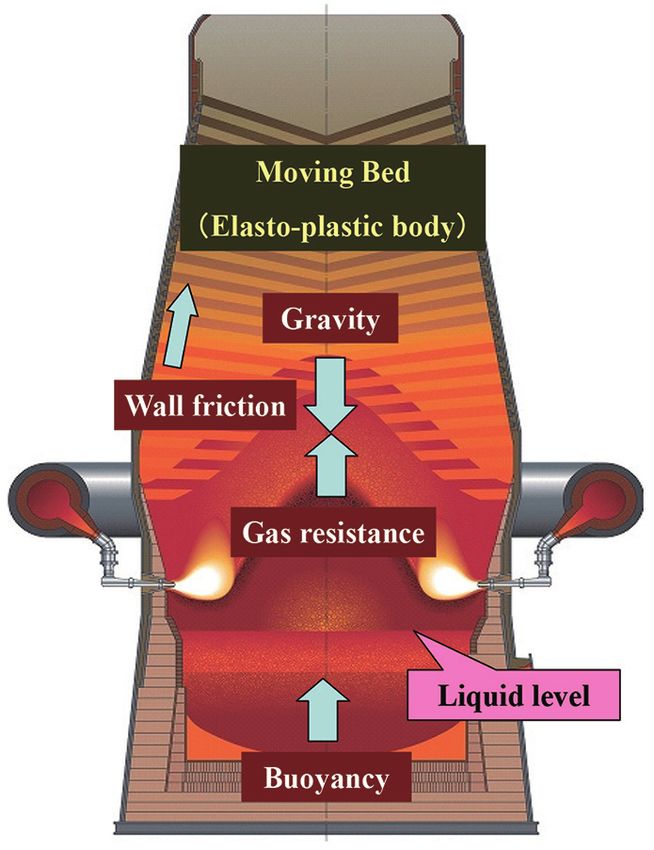
NIPPON STEEL TECHNICAL REPORT No. 123 March 2020

Fig. 7 Comparison of normal stresses on the wall between calculated                   Fig. 10 Comparison of calculated vertical stress by the mechanical
       results by the mechanical model on BF packed bed and measured                          model on BF packed bed with measured one during filling raw
       results (1/20 cold model experiment)                                                   materials in Kokura 2BF

                                                                                      Therefore, the Mathematical model for the transient erosion process
                                                                                      of the BF hearth was developed to estimate the hot metal flow in the
                                                                                      hearth, and to estimate the temperature distributions of hearth and
                                                                                      hearth refractories, and further, to estimate the transient hearth re-
                                                                                      fractory erosion. 6, 7)
                                                                                          Figure 11 shows the calculation flow of the Mathematical model
                                                                                      for the transient erosion process of the BF hearth. The final refracto-
                                                                                      ry erosion state is obtained in the following manner. First, the fol-
                                                                                      lowing are the input conditions: first the radial distributions of the
                                                                                      amount and the temperature of the hot metal and the molten slag
                                                                                      dripping to the hearth and the particle diameter and the void fraction
                                                                                      of the deadman coke, both calculated from the aforementioned 3D
                                                                                      dynamic simulator for BF, and second, the deadman coke sinking
                                                                                      level for the hearth and its bottom end profile calculated by the Me-
Fig. 8 Comparison of normal stresses on the bottom between calculated                 chanical model on the BF packed bed as shown in Fig. 12. Next, the
       results by the mechanical model on BF packed bed and measured                  liquid flow in the hearth and the heat transfer phenomena to the
       results (1/20 cold model experiment)                                           hearth refractories are analyzed. The refractory part susceptible to
                                                                                      the eroding condition is eroded by the model, and the cycle of cal-
                                                                                      culating the flow, heat transfer and the refractory erosion is repeated
                                                                                      until the final erosion state is obtained.
                                                                                          By core-sampling the residual refractories and the in-furnace re-
                                                                                      sidual material after blow-out (dissection survey), and by comparing
                                                                                      the analysis result with the actual state of the erosion and verifying
                                                                                      thereby, models having higher accuracies could have been devel-
                                                                                      oped. Figure 13 shows the comparisons of the model calculation re-
                                                                                      sult with the actually measured remaining refractory thickness ob-
                                                                                      tained by the boring survey conducted at the dismantling of the
                                                                                      hearth of the Wakayama No. 4 Blast Furnace and the Kokura No. 2
 Fig. 9 Vertical stress distribution calculated by the mechanical model               Blast Furnace, which prove that the erosion is simulated with high
        on BF packed bed during filling raw materials in Kokura 2BF                   accuracy. 5, 8)

blow-in in the Kokura No. 2 Blast Furnace, and in Fig. 10, the com-                   4. Development of Blast Furnace Life Extension
parison of the measured result and the calculated result of the bot-                     Technologies
tom vertical stresses at the same time is shown. The Mechanical                       4.1 Development of hearth refractory erosion suppressing tech-
model on the BF packed bed is able to estimate the vertical stresses                      nologies
accurately even in the production blast furnace.                                          As a result of the sensitivity analysis conducted for various op-
3.3 Mathematical model for transient erosion process of BF                            eration conditions by using the developed models regarding the
    hearth                                                                            hearth structure of the Wakayama No. 4 Blast Furnace, it was sug-
    Since the blast furnace in-hearth states are difficult to capture di-             gested that the sinking level of the deadman coke exerts a significant
rectly except their refractory temperature by direct measurement,                     influence upon the erosion of the hearth refractories. Figure 14
the estimation based on theory is important, and is the sole means.                   shows the influence of the deadman coke sinking level in the hearth

                                                                            - 113 -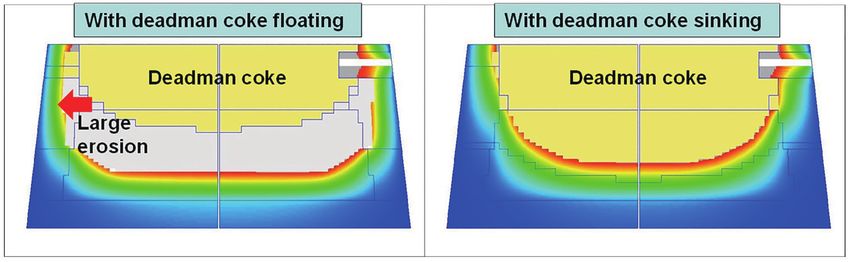
NIPPON STEEL TECHNICAL REPORT No. 123 March 2020

     Fig. 11 Flowchart of the mathematical model for transient erosion process of blast furnace hearth          Fig. 12 Sinking level and its shape calcu-
                                                                                                                        lated by the mechanical model on
                                                                                                                        BF packed bed

Fig. 13 Comparison of erosion profile of hearth between calculated results by the mathematical model for transient erosion process of BF and measured
        ones

                                  Fig. 14 Influence of deadman coke level in hearth on erosion of hearth refractories

on the erosion of hearth refractories. 5) In the case that the deadman                   Then, the deadman coke sinking level (the distance between the
coke floats, a coke-free layer (a region without coke) appears on the                tap hole level and the bottom end of the deadman coke) obtained by
side wall wherein the hot metal flow is intensified, and it is consid-               the one dimensional simplified calculation of the mechanics of the
ered that, as a result thereof, the heat load increases, and the refrac-             balance of the BF packed bed is taken as an index, and the relation-
tory erosion progresses.                                                             ship between the index and the actual furnace hearth refractory tem-

                                                                           - 114 -
NIPPON STEEL TECHNICAL REPORT No. 123 March 2020

Fig. 15 Relation between index of deadman coke level and temperature                 Fig. 17 Technologies of design for blast furnace with combining mathe-
        of sidewall of hearth                                                                matical blast furnace models

       Fig. 16 Transition of maximum erosion of hearth refractories estimated by measured temperature of hearth in Wakayama 4 BF and 5 BF

perature is shown in Fig. 15. 9, 10) A good correlation with the actual              BF, the Mechanical model on the BF packed bed and the Mathemat-
furnace operation result is confirmed, and it is proved that the dead-               ical model for the transient erosion process of the BF hearth as
man coke sinking level is a significant factor that influences the                   shown in Fig. 17, 5) the design guidance has been provided to the
hearth refractory temperature.                                                       blast furnace shape design to realize high operation efficiency and
    Based on this information and by using the abovementioned in-                    stabilized operation, and to the hearth structure design to provide
dex as a control parameter, and by controlling this index in the ordi-               high erosion resistance to hearth refractories. The blast furnace
nary operation design and the daily operation control (by changing                   shape design and the hearth structure design based on the blast fur-
the blast rate, oxygen blasting ratio, coke ratio and the like), a tech-             nace mathematical models are described hereunder.
nology to control the heat load to the hearth has been established.                  5.1 Blast furnace design
    As a result thereof, as shown in Fig. 16, in the Wakayama No. 4                      The inner shape of a blast furnace (blast furnace shape) exerts a
Blast Furnace, with respect to the progress of the hearth erosion in                 significant influence upon the blast furnace operation, and is a cru-
the maximum erosion progress direction until the blow-out in 2009,                   cial subject in the design of a blast furnace. As shown in Fig. 18, in
the progress of the erosion of the hearth sidewall was suppressed af-                the blast furnace shape design of the Blast Furnaces of Kokura,
ter 1996, and the progress of the erosion of the hearth bottom was                   Kashima and Wakayama, under the management condition of pro-
suppressed after 1992. In addition, similarly in the Wakayama No. 5                  duction amount and spatial restriction, two independent parameters
Blast Furnace, the progress of large erosion of the sidewall and the                 (bosh angle and belly height) had to be determined. Contrarily to the
bottom was suppressed up to its blow-out in 2019.                                    past blast furnace design method based on empirical rules, as shown
                                                                                     in Fig. 19, 5) by using the blast furnace mathematical models, the
5. Application to Blast Furnace Design                                               evaluation of the stability of the blast furnace with respect to the in-
   By the integrated application of the 3D dynamic simulator for                     furnace permeability and fluidization (channeling) was conducted,

                                                                           - 115 -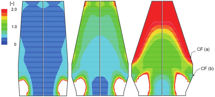
NIPPON STEEL TECHNICAL REPORT No. 123 March 2020

and the result was provided as the guideline for the blast furnace                  the pressures within the BF packed bed, and σyy: vertical stresses
shape design. 11, 12)                                                               within the BF packed bed. The CF value exceeding 1.0 means gas
    In particular, regarding the fluidization (channeling), by using                channeling theoretically, and therefore, CF needs to be below 1.0 in
the Mechanical model on the BF packed bed, the channeling factor                    the entire region except the raceway region.
(CF) was defined as Form (1), and the stability was evaluated.                          Figure 20 shows the effect of the furnace shape on the in-fur-
                                      ΔP                                            nace vertical stresses. The in-furnace vertical stresses change de-
          Channeling factor (CF) = σ 		                      (1)
                                        yy                                          pending on the furnace shape. Figure 21 shows the effect of the fur-
where ΔP: pressure difference between the furnace top pressure and                  nace shape on the in-furnace CF. Depending on the furnace shape,
                                                                                    CFs in the neighborhoods of the shaft section wall (a) and the belly
                                                                                    section wall (b) change in particular. Figure 22 shows the relation-
                                                                                    ship between the belly height and the peak value of CF in the neigh-
                                                                                    borhood of a wall. 5) As the belly height increases, CF in the neigh-
                                                                                    borhood of the shaft section wall CF(a) decreases, while CF in the
                                                                                    neighborhood of the belly section wall CF(b) increases when the
                                                                                    belly height exceeds 1.5 m.
                                                                                        Figure 23 shows the relationship between the bosh angle and
                                                                                    the pressure drop. 5) It shows that the pressure drop is smallest in the
                                                                                    neighborhood of the bosh angle of 79 degrees. Thus, by conducting

                                                                                       Fig. 20 Influence of inner shape of blast furnace on vertical stress

  Fig. 18 Target valuables for design of inner shape of blast furnace

                                                                                            Fig. 21 Influence of inner shape of blast furnace on CF

Fig. 19 Flowchart of design for inner shape of blast furnace with math-             Fig. 22 Relation between belly height and peak values of channeling
        ematical blast furnace models                                                       factor at wall

                                                                          - 116 -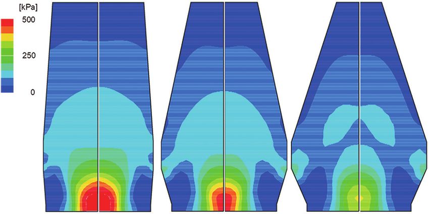
NIPPON STEEL TECHNICAL REPORT No. 123 March 2020
Fig. 23 Relation between bosh angle and pressure drop
simulations for various furnace shapes, the furnace shape with the
low in-furnace pressure drop and with low danger of channeling is
adopted (low probability of material fluidization occurrence, and
excellent in in-furnace material flow stability).
5.2 Hearth refractory structure design
The blast furnace hearth refractories are unreplaceable in the Fig. 24 Effect of hearth depth on erosion of hearth refractories
daily operation even with the modern technologies. The design of a
hearth of a new blast furnace including the refractories layout is as
important as the design of the blast furnace shape. Upon the study
on the design of the hearth structure of a new blast furnace, as de-
scribed earlier, the hearth design needs to be scrutinized and evalu-
ated; first based on the sinking level and the bottom end profile of
the deadman coke obtained from the dripping hot metal quantity
distribution and the temperature distribution thereof calculated by
the 3D dynamic simulator for BF and the Mechanical model on the
BF packed bed, and second, by estimating the erosion profile of the
hearth refractories by providing the subject refractory layout and the
hearth structure condition to the Mathematical model for the tran-
sient erosion process of the BF hearth.
In Fig. 24, the effect of the depth of the hearth on the hearth re-
fractory erosion is shown. 5) It is suggested that securing the suffi-
cient depth of the hearth in the initial stage is important, and as Fig. 25 Relation between hearth diameter and hearth depth of blast
shown in Fig. 25, the hearth depths of the Blast Furnaces of furnace in Wakayama, Kokura and Kashima
Wakayama, Kokura and Kashima, all blown-in in and after 2002,
are designed to be higher than those of the past Blast Furnaces. Furnaces and the Wakayama No. 1 and 2 Blast Furnaces have been
designed and constructed for a life of over twenty-five years.
6. Conclusion Hereinafter, we are determined to continue to make efforts to en-
The Wakayama No. 4 Blast Furnace that was originally designed hance the accuracy of the blast furnace mathematical models by in-
for an operating life of seven years maintained operation for longer teracting with the actual furnace operation data, intending to further
than twenty-seven years (blown-out on the 10 001st day), establish- stabilize the blast furnace operation, enhance the operation efficien-
ing the then world record in terms of continuous operation life. Fur- cy and suppress the carbon dioxide gas emission, and to further so-
thermore, the Wakayama No. 5 Blast Furnace that was blown-in in phisticate the blast furnace life extension technologies and the new
February 1988 achieved the world-record long continuous operation blast furnace design technologies.
days of 11 289 (thirty years and eleven months) until its blow-out in
January 2019. The element technologies of blast furnace life exten- References
sion established in the Wakayama No. 4 and 5 Blast Furnaces were 1) Takatani, K., Inada, T., Ujisawa, Y.: ISIJ Int. 39 (1), 15 (1999)
2) Katayama, K., Wakabayashi, S., Inada, T., Takatani, K., Yamaoka, H.:
applied not only to our own company’s blast furnaces, but also to
Tetsu-to-Hagané. 83 (2), 91 (1997)
other steel companies’ blast furnaces through technical cooperation 3) Katayama, K., Wakabayashi, S., Inada, T., Takatani, K., Yamaoka, H.:
and/or technical support, contributing greatly to their blast furnace Sumitomo Metals. 50 (2), 51 (1998)
life extension. 4) Inada, T. et al.: ISIJ Int. 43 (9), 1376 (2003)
The blast furnace mathematical models, well-advanced in terms 5) Nakano, K., Ujisawa, Y., Inada, T., Takatani, K., Oboso, A., Katayama, K.,
Yamasaki, H. Katagishi, H.: Bull. Iron Steel Inst. Jpn. 17 (3), 146 (2012)
of accuracy and practical usability realized by incorporating the ex- 6) Takatani, K., Inada, T., Takata, K.: ISIJ Int. 41 (10), 1139 (2001)
pertize from the actual operation, have been applied not only to the 7) Inada, T., Yamamoto, T., Sunahara, K., Yamaoka, H., Takatani, K., Miya
life extension of the existing blast furnaces, but also to the newly hara, M., Hatano, Y., Takata, K., Sato, Y.: Sumitomo Metals. 50 (2), 42
constructed blast furnaces, and the Kashima No. 1 and No. 3 Blast (1998)
- 117 -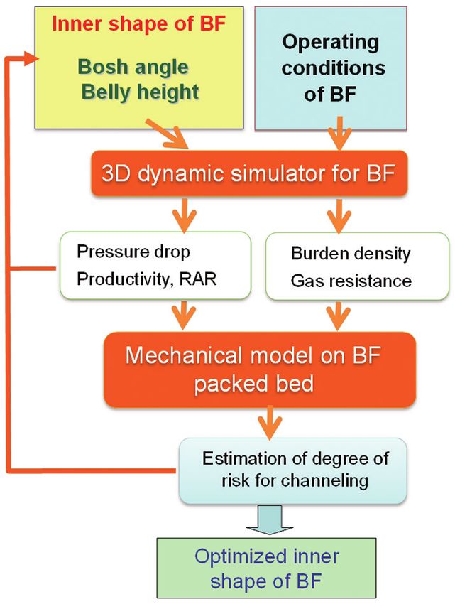
NIPPON STEEL TECHNICAL REPORT No. 123 March 2020

 8) Inada, T., Kasai, A., Nakano, K., Komatsu, S., Ogawa, A.: ISIJ Int. 49 (4),
    470 (2009)
 9) Nakano, K. et al.: Japanese Patent. Registration No. 3788114
10) Oboso, A.: Japanese Patent. Registration No. 4124011
11) Inada, T., Takata, K., Takatani, K., Yamamoto, T.: ISIJ Int. 43 (7), 1003
    (2003)
12) Inada, T., Takatani, K., Takata, K., Yamamoto, T.: ISIJ Int. 43 (8), 1143
    (2003)

                 Kaoru NAKANO                                                               Atsuhiro OBOSO
                 Chief Researcher                                                           General Manager, Head of Dept.
                 Ironmaking Research Lab.                                                   Ironmaking Technical Dept.
                 Process Research Laboratories                                              Ironmaking Div.
                 20-1 Shintomi, Futtsu City, Chiba Pref. 293-8511                           Wakayama Works

                 Yutaka UJISAWA                                                             Kenji KATAYAMA
                 Dr. Environmental Studies                                                  General Manager, Head of Div.
                 General Manager, COURSE50 Sub-project Leader                               Ironmaking Div.
                 R & D Planning Div.                                                        Oita Works

                 Takanobu INADA
                 Dr. Eng.
                 R & D Planning Div.

                                                                                  - 118 -
You can also read