ELF-500 User's Manual - Economic, Low-profile Fanless Industrial Box Computer
←
→
Page content transcription
If your browser does not render page correctly, please read the page content below
ELF-500
Economic, Low-profile Fanless Industrial Box Computer

User’s Manual

                         Ver. 1.00

                       April 13, 2009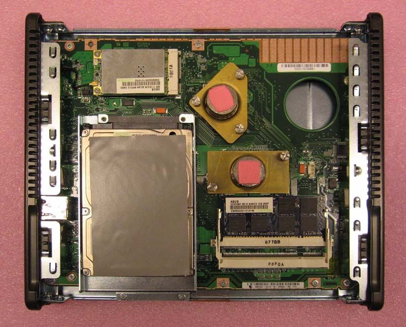
ELF-500

Contents
   Safety information............................................................................................................4
   About this guide...............................................................................................................5
1 Product Introduction .....................................................................................................8
  1.1 Welcome! ................................................................................................................8
  1.2 Package Contents...................................................................................................8
  1.3 Features ..................................................................................................................9
  1.4 ELF-500 Specifications .........................................................................................11
  1.5 External I/O ...........................................................................................................13
  1.6 Mechanical Dimensions ........................................................................................14
  1.7 Before you proceed...............................................................................................15
2 Assembly......................................................................................................................17
  2.1 Accessing Internal Components............................................................................17
               Removing the Cover..................................................................................................... 17
               Replacing the Cover ..................................................................................................... 18
   2.2 Internal Layout ......................................................................................................19
   2.3 System Memory ....................................................................................................20
               Overview ...................................................................................................................... 20
               Memory Configurations ................................................................................................ 20
               Installing a Memory Module ......................................................................................... 20
               Removing a Memory Module ....................................................................................... 21
   2.4 Hard Disk Drive .....................................................................................................22
               Overview ...................................................................................................................... 22
               Removing the Hard Disk Drive ..................................................................................... 22
               Installing the Hard Disk Drive ....................................................................................... 24
   2.5 Mini PCIe Card Slot...............................................................................................25
               Removing the Mini PCIe WLAN Card........................................................................... 25
               Installing the Mini PCIe WLAN Card............................................................................. 25
   2.6 Installing the Antenna............................................................................................26
   2.7 Installing the VESA Mount Bracket .......................................................................27
3 Getting Started.............................................................................................................29
  3.1 Power Connection.................................................................................................29
  3.2 Operating System and Drivers ..............................................................................30

2 ELF-500 User’s Manual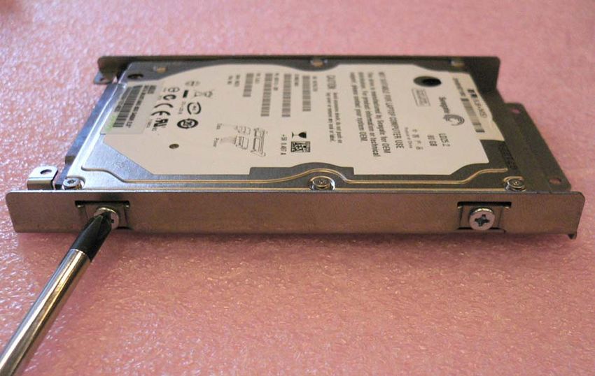
User’s Manual

4 BIOS Setup...................................................................................................................32
  4.1 Entering BIOS Setup Utility ...................................................................................32
               Navigation .................................................................................................................... 33
               Hotkey Legend ............................................................................................................. 34
   4.2 Main Setup ............................................................................................................35
               System Time/Date ........................................................................................................ 35
               SATA1 .......................................................................................................................... 36
               System Information ...................................................................................................... 36
   4.3 Advanced BIOS Setup ..........................................................................................37
               CPU Configuration ....................................................................................................... 38
               USB Configuration........................................................................................................ 38
               Advanced Chipset Settings .......................................................................................... 40
               Onboard Devices Configuration ................................................................................... 41
   4.4 Power Setup..........................................................................................................42
               Suspend Mode ............................................................................................................. 42
               ACPI 2.0 Support ......................................................................................................... 43
               APM Configuration ....................................................................................................... 43
   4.5 Boot Settings.........................................................................................................45
               Boot Device Priority ...................................................................................................... 45
               Hard Disk Drives .......................................................................................................... 46
               Boot Settings Configuration.......................................................................................... 46
               Security Settings .......................................................................................................... 48
   4.6 Exit Options...........................................................................................................50
               Exit & Save Changes ................................................................................................... 50
               Exit & Discard Changes ............................................................................................... 50
               Discard Changes .......................................................................................................... 50
               Load Setup Defaults ..................................................................................................... 50

                                                                                                    ELF-500 User’s Manual 3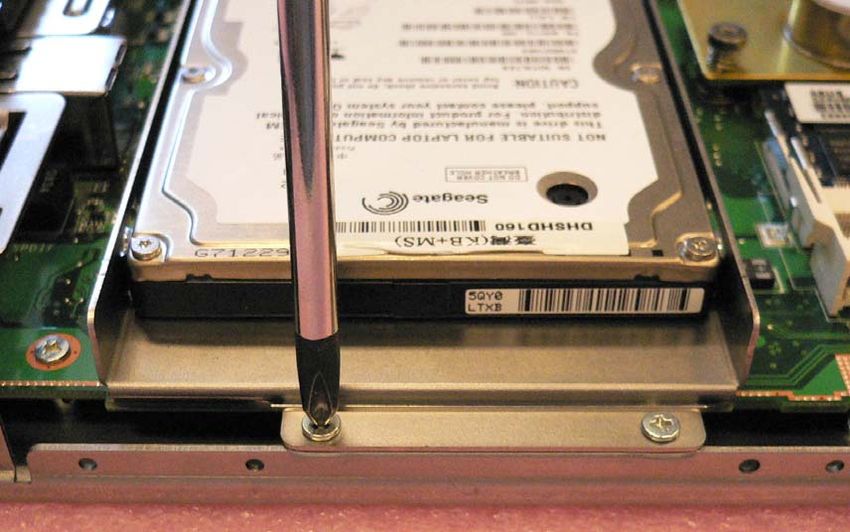
ELF-500

Safety information
Electrical safety
    • To prevent electrical shock hazard, disconnect the power cable from the electrical
      outlet before relocating the system.
    • When adding or removing devices to or from the system, ensure that the power
      cables for the devices are unplugged before the signal cables are connected. If
      possible, disconnect all power cables from the existing system before you add a
      device.
    • Before connecting or removing signal cables from the box computer, ensure that all
      power cables are unplugged.
    • Seek professional assistance before using an adapter or extension cord. These
      devices could interrupt the grounding circuit.
    • Make sure that your power supply is set to the correct voltage in your area.
    • If you are not sure about the voltage of the electrical outlet you are using, contact
      your local power company.
    • If the power supply is broken, do not try to fix it by yourself. Contact a qualified
      service technician or your retailer.

Operation safety
    • Before installing the box computer and adding devices on it, carefully read all the
      manuals that came with the package.
    • Before using the product, make sure all cables are correctly connected and the
      power cables are not damaged. If you detect any damage, contact your dealer
      immediately.
    • To avoid short circuits, keep paper clips, screws, and staples away from connectors,
      slots, sockets and circuitry.
    • Avoid dust, humidity, and temperature extremes. Do not place the product in any
      area where it may become wet.
    • Place the product on a stable surface.
    • If you encounter technical problems with the product, contact a qualified service
      technician or your retailer.

                       The symbol of the crossed out wheeled bin indicates that the
                       product (electrical and electronic equipment) should not be placed
                       in municipal waste. Check local regulations for disposal of
                       electronic products.

4 ELF-500 User’s Manual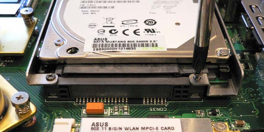
User’s Manual

About this guide
This user guide contains the information you need when installing and configuring the box
computer.

How this guide is organized
This manual contains the following parts:
y   Chapter 1: Product introduction
    This chapter describes the box computer features and specifications.
y   Chapter 2: Assembly
    This chapter describes the procedures for installing system components.
y   Chapter 3: Getting Started
    This chapter describes how to begin using your box computer.
y   Chapter 4: BIOS setup
    This chapter tells how to change system settings through the BIOS Setup menus.
    Detailed descriptions of the BIOS parameters are also provided.

Where to find more information
Refer to the following sources for additional information and for product and software
updates.
1. Advansus websites
The Advansus website provides updated information on Advansus hardware and software
products. Please go to http://www.advansus.com.tw/.
2. Optional documentation
Your product package may include optional documentation, such as warranty flyers, that
may have been added by your dealer. These documents are not part of the standard
package.

                                                               ELF-500 User’s Manual 5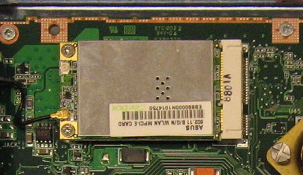
ELF-500

Conventions used in this guide
To make sure that you perform certain tasks properly, take note of the following symbols
used throughout this manual.
                        DANGER/WARNING: Information to prevent injury to yourself
                        when trying to complete a task.

                        CAUTION: Information to prevent damage to the components
                        when trying to complete a task.

                        IMPORTANT: Instructions that you MUST follow to complete a
                        task.
                        NOTE: Tips and additional information to help you complete a
                        task.

Typography
Bold text            Indicates a menu or an item to select
Italics              Used to emphasize a word or a phrase
                Keys enclosed in the less-than and greater-than sign means
                     that you must press the enclosed key
                     Example:  means that you must press the Enter or
                     Return key
++ If you must press two or more keys simultaneously, the key
                     names are linked with a plus sign (+)
                     Example: ++
Command              Means that you must type the command exactly as shown,
                     then supply the required item or value enclosed in brackets
                     Example: At the DOS prompt, type the command line:
                            afudoses /ixxxxx.rom
                            afudoses /iP5P800VM.ROM

6 ELF-500 User’s Manual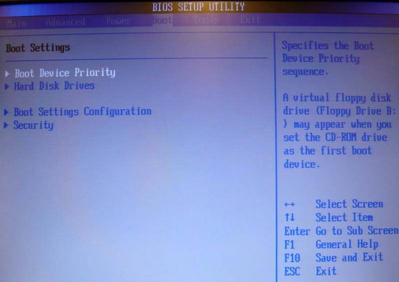
User’s Manual

This chapter describes the box
computer features and
specifications.

                                      Product
                                 Introduction 1
                                 ELF-500 User’s Manual 7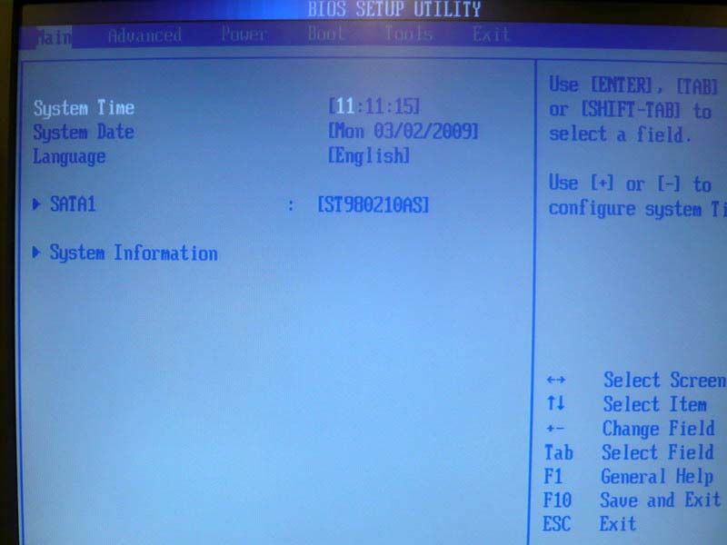
ELF-500

1     Product Introduction

1.1 Welcome!
Thank you for buying an ELF-500 Fanless Industrial Box Computer!
Before you start installing the box computer, and hardware devices on it, check the items in
your package and compare with the list below.

1.2 Package Contents
Check your box computer package for the following items.
Before you begin installing your single board, please make sure that the following materials
have been shipped:
    • 1x ELF-500
    • 1x power adapter
    • 1x power cord
    • 1x VESA mount bracket
    • 1x driver CD (with manual)
    • 1x antenna
    • 1x screw bag
         • M3 x 4.3mm (1 pcs)
         • M4 x 6mm (4 pcs)

                       If any of the above items is damaged or missing, contact your
                       retailer.

8 ELF-500 User’s Manual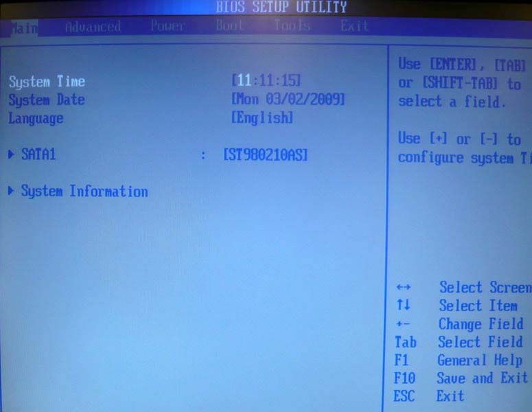
User’s Manual

1.3 Features
Product highlights
Low-profile Fanless Industrial Box Computer
The ELF-500 is an entry level Low-profile Fanless Industrial Box Computer ideal for Digital
Signage, Home Automation/Surveillance, and Thin Client applications. It is based on an
Atom N270 + 945GSE + ICH7M motherboard and features DVI-I, Gigabit Ethernet, wireless
LAN via Mini PCIe, SD/SDHC/MS/MS Pro card reader, and 2.5” SATA hard drive.

Intel® Atom™ N270 Processor
The Intel® Atom™ processor N270, implemented in 45nm technology, is power-optimized
and delivers robust performance-per-watt for cost-effective embedded solutions. Featuring
extended lifecycle support, this processor offers an excellent solution for embedded market
segments such as digital signage, interactive clients (kiosks, point-of-sale terminals), thin
clients, digital security, residential gateways, print imaging, and commercial and industrial
control. The processor remains software compatible with previous 32-bit Intel® architecture
and complementary silicon.

Intel® 945GSE Chipset
The mobile Intel® 945GSE Express Chipset provides power-efficient graphics and rich I/O
capabilities for cost-effective embedded solutions. It features an integrated 32-bit 3D
graphics engine based on Intel® Graphics Media Accelerator 950 (Intel® GMA 950)
architecture, a 533 MHz front-side bus (FSB), single-channel 400/533 MHz DDR2 system
memory (2x SODIMM), and Intel® High Definition Audio interface. The chipset consists of
the Intel® 82945GSE Graphics Memory Controller Hub (GMCH) and Intel® I/O Controller
Hub 7-M (ICH7-M). It delivers outstanding system performance and flexibility through
high-bandwidth interfaces such as PCI Express, Serial ATA, and Hi-Speed USB 2.0
connectivity.

DDR2 memory support
The box computer supports DDR2 memory to meet the bandwidth requirements of the
latest 3D graphics, multimedia, and Internet applications. The dual-channel DDR2
architecture doubles the bandwidth of your system memory to boost system performance,
eliminating bottlenecks with peak bandwidths of up to 8.5 GB/s.

                                                                ELF-500 User’s Manual 9
ELF-500

PCI Express Interface
The box computer fully supports PCI Express, the latest I/O interconnect technology that
speeds up the PCI bus. PCI Express features point‑to‑point serial interconnections
between devices and allows higher clock speeds by carrying data in packets.

Serial ATA Technology
The box computer supports the Serial ATA technology through the Serial ATA interfaces
and the Intel® ICH7 chipset. The SATA specification allows for thinner, more flexible cables
with lower pin count, reduced voltage requirement, and up to 300 MB/s data transfer rate.

S/PDIF Digital Sound Ready
The box computer supports a S/PDIF interface via a rear I/O jack. The S/PDIF technology
turns your computer into a high-end entertainment system with digital connectivity to audio
and speaker systems.

10 ELF-500 User’s Manual
User’s Manual

1.4 ELF-500 Specifications
System

CPU                    Intel Atom N270 1.6GHz
Chipset                945GSE+ICH7-M
Memory                 1x SODIMM DDR2-533 1GB , up to 2GB (2 slots)
Super I/O              W83627DHG-A
Storage                SATA 2.5” 80G
LAN Chip               Realtek 8111C
Audio Chip             Realtek ALC662
WLAN                   802.11 b/g/n via Mini PCIe card
Front I/O

LED                    Power / HDD LED
Button                 Power Button
Card reader            SD/SDHC/MS/MS Pro
USB Port               2x USB 2.0
Audio                  1x line out, 1x mic-in

Rear I/O

LAN Port               1x RJ45
USB Port               2x USB 2.0
Display                1x DVI-I
Power In               1x DC Jack
S/PDIF                 1x Jack
Antenna                1x antenna (2.0db)

Power
                       Input:AC100-240V 50/60Hz 1.0A
Power Adapter
                       Output: DC12V 3A

Mechanical

Dimensions             220.5 x 192 x 30 (mm)
Mounting               Desktop or VESA mount
                       Operating: 10g/11ms
Shock
                       Storage: 30g/11ms
                       Operating (IEC 60068-2-64-Fh): 5-500Hz, 1g (rms), 3-axes
Vibration
                       Storage (IEC 60068-2-64-6Fc): 5-500Hz,2g (rms), 3-axes
                       Operating: 0°C to 45°C, 0%~90%, non-condensing
Temperature/Humidity
                       Storage: -40°C to 60°C, 0%~90%, non-condensing

                                                                  ELF-500 User’s Manual 11
ELF-500
Other
Operating System Windows XP Embedded
CE/EN 300-440 (or EN 300328) + CE/EN 301-489
CE/EN 55022 + EN55024
FCC Part 15C, FCC Part 15B
CE/EN 60950-1
Certifications
CB
CCC
SRMC
UL + CUL
* Specifications are subject to change without notice.
12 ELF-500 User’s ManualUser’s Manual
1.5 External I/O
Front Panel
Line-out Card Reader HDD LED
Mic-in USB Power Button
Rear Panel
Antenna DVI-I S/PDIF
Power Input USB LAN
ELF-500 User’s Manual 13ELF-500
1.6 Mechanical Dimensions
Dimensions in mm
14 ELF-500 User’s ManualUser’s Manual
1.7 Before you proceed
Take note of the following precautions before you install box computer components or
change any box computer settings.
Unplug the power cord from the wall socket before touching any
component.
Use a grounded wrist strap or touch a safely grounded object or a
metal object, such as the power supply case, before handling
components to avoid damaging them due to static electricity
Hold components by the edges to avoid touching the ICs on them.
Whenever you uninstall any component, place it on a grounded
antistatic pad or in the bag that came with the component.
y Before you install or remove any component, ensure that
the power supply is switched off or the power cord is
detached from the power supply. Failure to do so may
cause severe damage to the box computer, peripherals,
and/or components.
ELF-500 User’s Manual 15ELF-500
This chapter describes the
procedures for installing system
components.
2
Assembly
16 ELF-500 User’s ManualUser’s Manual
2 Assembly
Make sure to unplug the power cord before opening the cover of the
box computer. Failure to do so can cause you physical injury and
damage system components.
2.1 Accessing Internal Components
Follow the procedure below to access the system's internal components.
Removing the Cover
1. Remove the four (4) screws securing the chassis cover as shown below.
ELF-500 User’s Manual 17ELF-500 2. Lift the chassis cover as shown below. Replacing the Cover To replace the chassis cover, reverse the steps described above and tighten the four (4) screws securing the cover to the chassis. 18 ELF-500 User’s Manual
User’s Manual

2.2 Internal Layout
The locations of the hard drive, SODIMM memory sockets, and Mini PCIe socket with
WLAN card installed are shown below

              Mini PCIe slot w/ WLAN card

                       2.5" SATA HDD                  SODIMM slots

                                                           ELF-500 User’s Manual 19
ELF-500
2.3 System Memory
Overview
The ELF-500 comes with two (2) stacked 200-pin DDR2 SODIMM sockets. A 1GB module
is pre-installed in the lower socket.
DDR2 modules have the same physical dimensions as a DDR DIMM but have a 200-pin
footprint compared to the 184-pin DDR DIMM. DDR2 DIMMs are notched differently to
prevent installation on a DDR DIMM socket. See Internal Layout above for the location of
the sockets.
Memory Configurations
You may install 64 MB, 128 MB, 256 MB, 512 MB and 1 GB unbuffered ECC or non-ECC
DDR SODIMMs into the SODIMM sockets. The maximum capacity is 2GB with 2 SODIMM
modules installed
Installing a Memory Module
Make sure to unplug the power supply before adding or removing
memory modules or other system components. Failure to do so may
cause severe damage to both the system and its components.
1. Unlock a SODIMM socket by pressing the retaining clips outward
2. Align a SODIMM on the socket such that the notch on the SODIMM matches the break
on the socket.
3. Firmly insert the SODIMM into the socket until the retaining clips snap back in place
and the SODIMM is properly seated.
z A DDR2 SODIMM is keyed with a notch so that it fits in only one
direction. DO NOT force a SODIMM into a socket to avoid damaging
the SODIMM.
z The DDR2 SODIMM sockets do not support DDR SODIMMs. DO
NOT install DDR SODIMMs to the DDR2 SODIMM socket.
20 ELF-500 User’s ManualUser’s Manual
Removing a Memory Module
1. Simultaneously press the retaining clips outward to unlock the SODIMM.
Support the SODIMM lightly with your fingers when pressing the retaining
clips. The SODIMM may be damaged by the "spring release" effect when
the clips are released.
2. Remove the SODIMM from the socket.
ELF-500 User’s Manual 21ELF-500
2.4 Hard Disk Drive
Overview
The ELF-500 comes with an 80GB 2.5" SATA hard disk drive pre-installed.
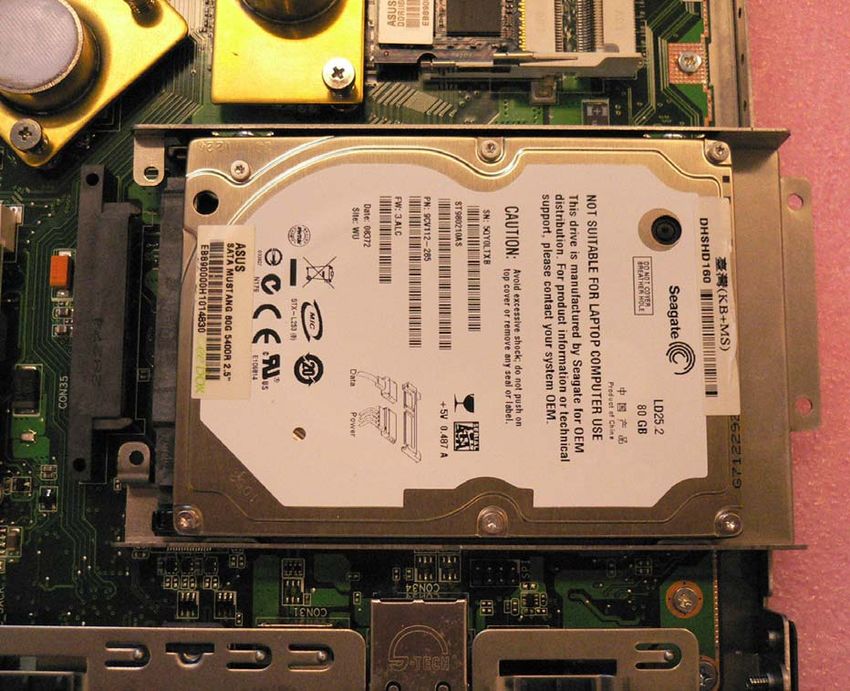
Removing the Hard Disk Drive
1. Carefully remove the thermal pad affixed to the hard disk drive and set aside.
2. Remove the hard disk drive, loosen the four (4) screws securing the hard drive
bracket to the system board as shown below.
22 ELF-500 User’s ManualUser’s Manual
3. Slide the hard drive/bracket assembly towards the edge of the chassis as indicated
by the large red arrow below to disconnect it from the connector on the system board.
The hard drive/bracket assembly can now be removed from the box computer.
onboard HDD connector
ELF-500 User’s Manual 23ELF-500
4. Remove the hard disk drive from the bracket by removing the four (4) screws as
shown.
Installing the Hard Disk Drive
To install a hard disk drive, reverse the steps for Removing the Hard Disk Drive described
above.
Be sure to replace the thermal pad removed in Step 1 before reinstalling
the chassis cover to prevent overheating of the hard disk drive.
24 ELF-500 User’s ManualUser’s Manual
2.5 Mini PCIe Card Slot
Make sure to unplug the power cord before adding or removing
expansion cards. Failure to do so may cause you physical injury and
damage system components.
Removing the Mini PCIe WLAN Card
1. Disconnect the antenna cable from the WLAN card as indicated below.
2. Remove the two (2) screws securing the card to the system board as indicated.
antenna cable
3. Slide the card in the direction indicated by the large red arrow above to remove it from
the Mini PCIe slot.
Installing the Mini PCIe WLAN Card
To install a Mini PCIe WLAN card, reverse the steps described above.
ELF-500 User’s Manual 25ELF-500 2.6 Installing the Antenna The ELF-500 comes with a WIFI antenna. To install the antenna, locate the antenna socket on the Rear Panel of the chassis (see 1.5 External I/O). Screw the antenna into the socket until it is securely attached as shown below. 26 ELF-500 User’s Manual
User’s Manual

2.7 Installing the VESA Mount Bracket
The ELF-500 comes with a VESA mount bracket and a screw bag containing:
        • one (1) M3 x 4.3mm screw
        • four (4) M4 x 6mm screws
The shorter M3 screw is used to secure the VESA mount bracket to the bottom of the
ELF-500 chassis. The four M4 screws are used to secure the box computer using the
VESA mount bracket to the desired location.

To attach the VESA mount bracket to the chassis, follow the procedure below.
   1. Place the VESA mount bracket against the bottom of the chassis as shown below.
   2. Loosely attach the M3 screw to through the keyhole in the bracket to the bottom of
       the chassis.
   3. Secure the captured screw to the side panel of the chassis, and then tighten the M3
       screw to complete the bracket installation

                                                                  M3 screw
                                           Front Panel
     VESA mount bracket

                                      captured screw

                                                             ELF-500 User’s Manual 27
ELF-500
This chapter describes how to
begin using your box computer.
3
Getting Started
28 ELF-500 User’s ManualUser’s Manual
3 Getting Started
Before you install the ELF-500, check the installation environment to ensure that the box
computer can be suitably and safely installed.
Make sure to unplug the power cord before installing or moving the
box computer. Failure to do so can cause you physical injury and
damage system components.
3.1 Power Connection
The ELF-500 comes with an AC power adapter (110~240 VAC input, 12 VDC output) and a
power cord suitable for your region. Connect the DC output of the power adapter to the DC
power input socket on the Rear Panel of the box computer. To power on the system, press
the power button on the Front Panel of the box computer.
Make sure to use the power cord suitable for your region. Do not
remove or alter the grounding prong on the power cord. In situations
where a two-slot receptacle is present, have it replaced with a
properly grounded three-prong grounding type receptacle.
ELF-500 User’s Manual 29ELF-500 3.2 Operating System and Drivers The ELF-500 does not come with an operating system pre-installed. You will need to install an operating system and the necessary drivers to operate it. After you have finished assembling your system and connected the power supply provided, power it up using the power switch and install the desired operating system. The ELF-500 has been qualified to run the Windows XP Embedded operating system. If you have purchased a license, the Windows XP Embedded operating system will be pre-installed on the ELF-500 at the factory. 30 ELF-500 User’s Manual
User’s Manual

This chapter describes use the BIOS
Setup Utility. Detailed descriptions of
the BIOS parameters are also
provided.

                                           BIOS Setup
                                                       4
                                          ELF-500 User’s Manual 31
ELF-500 4 BIOS Setup The following chapter describes basic navigation for the BIOS Setup Utility. 4.1 Entering BIOS Setup Utility To enter the BIOS Setup Utility, power on the system and press the key when boot-up screen appears. The Main BIOS Setup Menu will then display as below. The Main BIOS Setup Menu screen has two main frames. The left frame displays all the options that can be configured. “Grayed” options cannot be configured, “Blue” options can be. The right frame displays the key legend. Above the key legend is an area reserved for a text message. When an option is selected in the left frame, it is highlighted in white. A text message will often accompany it. 32 ELF-500 User’s Manual
User’s Manual

Navigation
The BIOS Setup Utility is designed to make it as easy to use as possible. Being a
menu-driven program, it lets you scroll through the various sub-menus and make your
selections from the available options using the navigation keys.

                    z    The default BIOS settings for this motherboard apply for most
                         conditions to ensure optimum performance. If the system
                         becomes unstable after changing any BIOS settings, load the
                         default settings to ensure system compatibility and stability.
                         Select the Load Setup Defaults item under the Exit Menu.
                    z    The BIOS setup screens shown in this section are for reference
                         purposes only, and may not exactly match what you see on
                         your screen.
                    z    Visit the Advansus website to download the latest BIOS file for
                         this motherboard.

                                                             ELF-500 User’s Manual 33
ELF-500
Hotkey Legend
The BIOS Setup Utility uses a hotkey-based navigation system. Most of the BIOS setup
utility hot keys can be used at any time during the setup navigation process.
Key(s) Function Description
→ ← Left/Right. The Left and Right < Arrow > keys allow you to select a
setup screen.
↑ ↓ Up/Down. The Up and Down < Arrow > keys allow you to select a
setup item or sub-screen.
+ - Plus/Minus The Plus and Minus < Arrow > keys allow you to change
the field value of a particular setup item.
Tab The < Tab > key allows you to select setup fields.
F8 The < F8 > key on your keyboard is the Fail-Safe key. It is not
displayed on the key legend by default. To set the Fail-Safe settings
of the BIOS, press the < F8 > key on your keyboard. It is located on
the upper row of a standard 101 keyboard. The Fail-Safe settings
allow the motherboard to boot up with the least amount of options set.
This can lessen the probability of conflicting settings.
F1 The < F1 > key allows you to display the General Help screen.
F10 The < F10 > key allows you to save any changes you have made and
exit Setup. Press the < F10 > key to save your changes.
ESC The < Esc > key allows you to discard any changes you have made
and exit the Setup. Press the < Esc > key to exit the setup without
saving your changes.
Enter The < Enter > key allows you to display or change the setup option
listed for a particular setup item. The < Enter > key can also allow
you to display the setup sub-screens.
34 ELF-500 User’s ManualUser’s Manual
4.2 Main Setup
When you first enter the Setup Utility, you will enter the Main setup screen. You can always
return to the Main setup screen by selecting the Main tab. There are two Main Setup
options. They are described in this section. The Main BIOS Setup screen is shown below.
System Time/Date
Use this option to change the system time and date. Highlight System Time or System Date
using the < Arrow > keys. Enter new values using the keyboard. Press the < Tab > key or
the < Arrow > keys to move between fields. The time is entered in HH:MM:SS format
(24-hour format). The date must be entered in MM/DD/YY format.
ELF-500 User’s Manual 35ELF-500 SATA1 Use this submenu to view the details of the onboard SATA hard disk drive. System Information Use this submenu to view information on the BIOS version, CPU and .memory. 36 ELF-500 User’s Manual
User’s Manual

4.3 Advanced BIOS Setup
Select the Advanced tab from the setup screen to enter the Advanced BIOS Setup screen.
You can select any of the items in the left frame of the screen, such as CPU Configuration,
to go to the sub menu for that item. You can display an Advanced BIOS Setup option by
highlighting it using the < Arrow > keys. The Advanced BIOS Setup screen is shown
below.

                                                               ELF-500 User’s Manual 37
ELF-500 CPU Configuration Use this submenu to view the details of the CPU settings. USB Configuration Use this submenu to view the enabled USB devices, and configure the USB Mass Storage Class Devices. 38 ELF-500 User’s Manual
User’s Manual

USB Mass Storage Device Configuration
Use this submenu to configure the USB Mass Storage Class Devices

USB Mass Storage Reset Delay
This option specifies amount of time the USB code should wait after issuing a reset to the
USB mass storage devices.

Emulation Type
Emulation Type can be set according to the type of attached USB mass storage device(s).
If set to Auto, USB devices less than 530MB will be emulated as Floppy and those greater
than 530MB will remain as hard drive. The Forced FDD option can be used to force a hard
disk type drive (such as a Zip drive) to boot as FDD.

                                                               ELF-500 User’s Manual 39
ELF-500 Advanced Chipset Settings Use this submenu to configure Advanced Chipset Settings. DRAM Frequency Set DRAM frequency. You can let frequency be set by BIOS automatically or configure it manually. Configure DRAM Timing by SPD This option enables/disables configuring of DRAM Timing by SPD. 40 ELF-500 User’s Manual
User’s Manual

Onboard Devices Configuration
Use this submenu to configure Onboard Devices.

Audio Controller
This option enables/disables the Audio Controller.

Onboard LAN
This option enables/disables the Onboard LAN.

Onboard LAN Boot ROM
Set this value to enable/disable the onboard LAN’s PXE ROM to enable boot from LAN.
Setting to Disabled can shorten the POST time without initializing LAN PXE ROM if boot
from LAN is not needed.

                                                             ELF-500 User’s Manual 41
ELF-500
4.4 Power Setup
Select the Power tab from the setup screen to enter the power management BIOS Setup
screen. You can select any of the items in the left frame of the screen to go to the sub menu
for that item. The power management BIOS Setup screen is shown below.
Suspend Mode
This option selects either S1 (POS) or S3 (STR) system suspend mode.
S1 (POS) z Power On Suspend - Under this setting the CPU is not
executing instructions, all power resources that supply system
level reference of S0 are off, system memory context is
maintained, devices that reference power resources that are on
are on, and devices that can wake-up the system can cause the
CPU to continue to execute from where it left off.
S3 (STR) z Suspend to RAM - Under this setting the system enters a low
power state instead of being completely shut off. This allows the
computer system to boot up in a few seconds.
42 ELF-500 User’s ManualUser’s Manual
ACPI 2.0 Support
This option enables/disables ACPI 2.0 support.
APM Configuration
Restore on AC Power Loss
This option determines which state the computer enters when AC power is restored after a
power loss. The options for this value are Last State, Power On and Power Off.
Power Off z Set this value to always power off the system while AC power is
restored.
Power On z Set this value to always power on the system while AC power is
restored.
Last State z Set this value to power off/on the system depending on the last
system power state while AC power is restored.
ELF-500 User’s Manual 43ELF-500 Power On By LAN This option enables/disables the LAN GPI to generate a wake event. Power On By RTC Alarm This option enables/disables the Real Time Clock's ability to generate a wake event. 44 ELF-500 User’s Manual
User’s Manual

4.5 Boot Settings

Boot Device Priority
This option determines the sequence in which the computer checks which device to boot
from.

                                                            ELF-500 User’s Manual 45
ELF-500 Hard Disk Drives This option specifies the boot sequence from the available disk drives. Boot Settings Configuration 46 ELF-500 User’s Manual
User’s Manual

Quick Boot
Allows BIOS to skip certain tests while booting. This will decrease the time needed to boot
the system.

Disabled               z   Set this value to allow the BIOS to perform all POST tests.
Enabled                z   Set this value to allow the BIOS to skip certain POST tests to
                           boot faster.

Full Screen Logo
This option enables/disables display of the Full Screen Logo during bootup.

Boot Num-Lock
Set this value to allow the Number Lock setting to be modified during boot up.

Off                    z   This option does not enable the keyboard Number Lock
                           automatically. To use the 10-keys on the keyboard, press the
                           Number Lock key located on the upper left-hand corner of the
                           10-key pad. The Number Lock LED on the keyboard will light up
                           when the Number Lock is engaged.
On                     z   Set this value to allow the Number Lock on the keyboard to be
                           enabled automatically when the computer system is boot up.
                           This allows the immediate use of 10-keys numeric keypad
                           located on the right side of the keyboard. To confirm this, the
                           Number Lock LED light on the keyboard will be lit.

Wait For F1 If Error
BIOS POST error messages are followed by: Press  to continue. If this option is set to
Disabled, BIOS does not wait for you to press the  key after an error message. The
settings are Disabled or Enabled.

                                                                ELF-500 User’s Manual 47
ELF-500 Security Settings Two Levels of Password Protection BIOS provides both a Supervisor and a User password. If you use both passwords, the Supervisor password must be set first. The system can be configured so that all users must enter a password every time the system boots or when Setup is executed, using either or either the Supervisor password or User password. The Supervisor and User passwords activate two different levels of password security. If you select password support, you are prompted for a one to six character password. Type the password on the keyboard. The password does not appear on the screen when typed. Make sure you write it down. If you forget it, you must drain NVRAM and re-configure. Remember the Password Keep a record of the new password when the password is changed. If you forget the password, you must erase the system configuration information in NVRAM. To access the sub menu for the following items, select the item and press < Enter >: 48 ELF-500 User’s Manual
User’s Manual

       • Change Supervisor Password

       • Change User Password

       • Clear User Password

Supervisor Password
Indicates whether a supervisor password has been set.

User Password
Indicates whether a user password has been set.

Change Supervisor Password
Select this option and press < Enter > to access the sub menu. You can use the sub menu
to change the supervisor password.

Change User Password
Select this option and press < Enter > to access the sub menu. You can use the sub menu
to change the user password.

                                                            ELF-500 User’s Manual 49
ELF-500 4.6 Exit Options Select the Exit tab from the setup screen to enter the Exit BIOS Setup screen. You can display an Exit BIOS Setup option by highlighting it using the < Arrow > keys. The Exit BIOS Setup screen is shown below. Exit & Save Changes When you have completed the system configuration changes, select this option to leave Setup and reboot the computer so the new system configuration parameters can take effect. Exit & Discard Changes Select this option to quit Setup without making any permanent changes to the system configuration. Discard Changes Select this option to discard changes to the system configuration. Load Setup Defaults Automatically sets all Setup options to a complete set of default settings when you select this option. 50 ELF-500 User’s Manual
You can also read