Asymmetric Double Freeform Surface Lens for Integrated LED Automobile Headlamp
←
→
Page content transcription
If your browser does not render page correctly, please read the page content below
micromachines

Article
Asymmetric Double Freeform Surface Lens for Integrated LED
Automobile Headlamp
Hui Zhang 1 , Dengfei Liu 1,2 , Yinwan Wei 1,2 and Hong Wang 1,2, *

                                          1   Engineering Research Center for Optoelectronics of Guangzhou Province, School of Physics and
                                              Optoelectronics, South China University of Technology, Guangzhou 510640, China;
                                              201820127932@mail.scut.edu.cn (H.Z.); eedfliu@mail.scut.edu.cn (D.L.);
                                              202020130343@mail.scut.edu.cn (Y.W.)
                                          2   Guangdong Provincial Engineering Research Center for Wide Bandgap Semiconductor Chips and
                                              Application, Zhongshan Institute of Modern Industrial Technology, South China University of Technology,
                                              Zhongshan 528437, China
                                          *   Correspondence: phhwang@scut.edu.cn; Tel.: +86-20-87111557

                                          Abstract: We propose a design method of asymmetric double freeform surface lens for an integrated
                                          LED automobile headlamp and develop an integrated LED automobile optical system. A single
                                          asymmetric double freeform surface lens is designed to redistribute rays emitting from the light
                                          source for realizing both low and high beams. Moreover, a freeform surface reflector is used to
                                          improve the energy efficiency of high beams. The prism placed in the optical path can suppress
                                          chromatic dispersion on the edge of the target plane. Simulation and experimental results show that
                                          the illumination values and color temperature of the key points can fully meet the requirements of
                                          United Nations Economic Commission for Europe vehicle regulations (ECE) R112, 48, and 128. The

                                   volume of the whole optical system comprised of freeform surface elements is smaller than that of
                                          the low beam system of a traditional headlamp, resulting in saved space, in which other electronic
Citation: Zhang, H.; Liu, D.; Wei, Y.;
                                          devices can be installed for the safety of the driver, which indicates that the proposed method is
Wang, H. Asymmetric Double
                                          practical in the field of automobile lighting.
Freeform Surface Lens for Integrated
LED Automobile Headlamp.
Micromachines 2021, 12, 663. https://
                                          Keywords: asymmetric double freeform surface lens; LED; integrated automobile headlamp; freeform
doi.org/10.3390/mi12060663                surface optics

Academic Editors: W.B. Lee and
Lihua Li
                                          1. Introduction
Received: 5 May 2021                           LEDs have gradually entered our lives due to their advantages of energy saving,
Accepted: 4 June 2021
                                          high energy efficiency, long lifespan, and miniaturization [1,2]. In the past decade, LEDs
Published: 5 June 2021
                                          have been used increasingly as light sources in automobile headlamps for their excellent
                                          properties [3–6]. Since low-beam requirements are completely different from those of high
Publisher’s Note: MDPI stays neutral
                                          beams, the traditional optical systems of low and high beams in headlamps are designed
with regard to jurisdictional claims in
                                          separately, mainly including projection and reflection types. In general, projection-type
published maps and institutional affil-
                                          optical systems deflect by lenses and reflection type by reflectors [7]. It is easy to form
iations.
                                          a clear cutoff line but hard to improve the energy efficiency for projection types with a
                                          baffle plate; conversely, the reflection type without a baffle plate is more efficient but has
                                          a dim cutoff line. Previously, Cvetkovic et al. presented a simultaneous multiple surface
                                          (SMS) 3D method for automobile low and high beam headlamps, whose optical efficiency
Copyright: © 2021 by the authors.
                                          is more than 75% [8,9]. Domhardt et al. designed a combined lens for LED-based low
Licensee MDPI, Basel, Switzerland.
                                          beam headlamp but needed large space to install lenses for high energy efficiency [10].
This article is an open access article
                                          Ge et al. used an elliptical and parabolic reflector to design a low beam headlamp that
distributed under the terms and
                                          had high energy efficiency [5]. Hsieh et al. proposed a modular design for an LED
conditions of the Creative Commons
                                          vehicle projector headlamp that provided the cutoff line of low beams without a baffle
Attribution (CC BY) license (https://
                                          plate [11]. Chu et al. proposed a low beam headlamp with a compound ellipsoidal reflector
creativecommons.org/licenses/by/
4.0/).
                                          that achieved the highest energy efficiency in the existing literature [12]. In the past,

Micromachines 2021, 12, 663. https://doi.org/10.3390/mi12060663                                      https://www.mdpi.com/journal/micromachines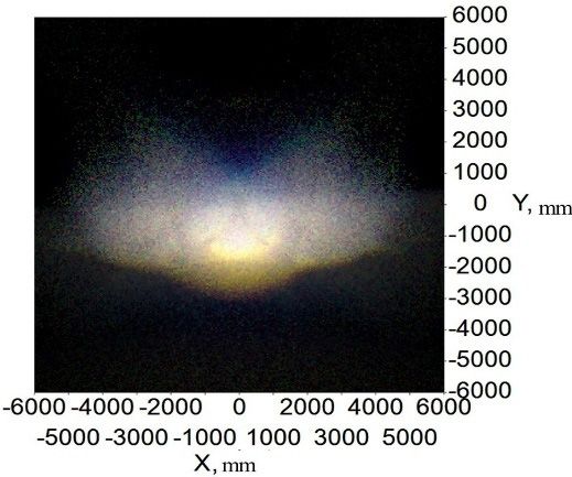
Micromachines 2021, 12, 663                                                                                            2 of 16

                              our research group has proposed several optical systems for headlamps. For example,
                              an optical system with a single freeform surface lens [13], a low chromatic dispersion
                              headlamp system using a parabolic reflector and micro-lens array [14], a LED motorcycle
                              headlight using a combined lens [15], etc. More separate design methods for low and high
                              beams can be found in references [16–21]. In recent years, compact headlamp design has
                              become more and more fashionable [22]. The integrated headlamp reduces its volume
                              by sharing some optical elements between low- and high-beam systems, allowing the
                              designs of integrated headlamps to fit with the trend of compact design. However, few
                              studies in the literature have been reported about the integrated headlamp. Hung et al.
                              designed an integrated headlamp incorporating a digital micromirror device [23]. Wu et al.
                              presented a modular LED headlamp system based on a freeform reflector [24]. Borocki
                              et al. recommended a single optical system with both a low beam and a high beam, in
                              which switching between the low beam and high beam was achieved by a removable
                              shutter [25]. M. Rice et al. proposed an integrated headlamp based on a projective low-
                              beam system, in which the light emitted from the high-beam source was reflected by the
                              lower plane of the baffle plate and deflected by the lens to form the illumination distribution
                              of high beams [26]. In previous studies, most of the headlamps were designed individually,
                              which may increase the complexity and volume of the headlamp. Existing integrated
                              headlamps with a removable shutter may affect the reliability of the headlamp. Therefore,
                              it is necessary to study a simple and small-volume headlamp system.
                                     In this paper, we proposed a method of designing an asymmetric double freeform
                              surface lens (ADFSL) and developed an integrated LED automobile optical system. On
                              the premise of meeting the requirements of ECE R112, 48, and 128 [27–29], this new
                              integrated LED headlamp system can greatly improve the compactness of the optical
                              system and suppress chromatic dispersion at the edge of the target illumination area. Just
                              one lens is needed to achieve low and high beams, which means that this new headlamp
                              system can save a lot of space. A freeform surface reflector focusing light is proposed to
                              improve energy efficiency. Furthermore, a prism is placed in the optical path to reduce
                              the chromatic dispersion further, which can provide comfortable and safe lighting for the
                              driver. Compared to the traditional, separated headlamp and integrated headlamp, the
                              proposed headlamp has only one single lens to achieve low and high beams, reducing
                              the volume of the automobile headlamp. Furthermore, the color distribution on the target
                              plane using ADFSL and prism is more stable.

                              2. Design Method
                                   The optical system of the new integrated headlamp is shown in Figure 1. The whole
                              system consists of an ADFSL, a freeform surface reflector, a prism, a baffle, and two LEDs.
                              The optical system of the low beam includes a LED source, an upper half of the ADFSL,
                              and a baffle plate. Correspondingly, the optical system of the high beam comprises a
                              freeform surface reflector, a prism, the lower half of the ADFSL, and a LED source. Rays
                              emitting from the low beam LED source are partially blocked by the baffle plate and then
                              redistributed by the ADFSL, forming a low beam with a clear cutoff line on the target plane.
                              On the other hand, rays from the high beam LED source are focused on a point by the
                              freeform surface reflector and then deflected by the prism. Finally, the remaining rays will
                              be redistributed by the ADFSL to form the illumination distribution of the high beam. The
                              implementation of the low and high beams will be described in detail below.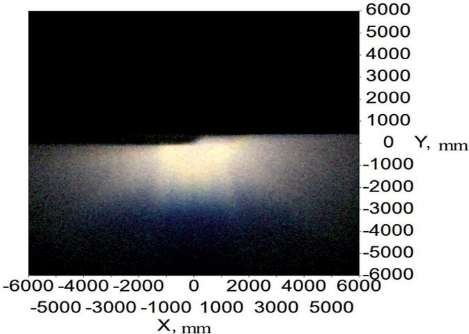
romachines 2021, 12, 663
omachines 2021, 12, 663
Micromachines 2021, 12, 663 3 of 16
Figure 1. Optical system of the integrated LED automobile headlamp.
2.1. Optical System of the Low Beam Mode
Figure 1. Optical system of the integrated LED automobile headlamp.
Figure 1. Optical
Over system
the past of the
decade, integrated
a series LED automobile
of regulations headlamp.
have been introduc
2.1. Optical System of the Low Beam Mode
Low beam is mainly used for good road lighting and cannot cause
Over the past decade, a series of regulations have been introduced for driver’s safety.
2.1. Optical
drivers. System of
Low beam isAccording
mainly used for
the
togood Low
theroad
ECE Beam
R112
lighting
Mode
andregulations, the
cannot cause glare tested
to the points a
opposing
drivers.Over
According to the
the past ECE R112 regulations, the tested points and the cutoff line are
shown in Figure
shown in Figure 2.
2. decade, a series of regulations have been introd
Low beam is mainly used for good road lighting and cannot cau
drivers. According to the ECE R112 regulations, the tested point
shown in Figure 2.
Figure 2. Tested
Figure points and
2. Tested regions
points of low
and beam. of low beam.
regions
It can be found that the light shape of the low beam has a wide horizontal spread for
both sides,
It canwhich
becan providethat
found a big the
anglelight
of viewshape
for drivers. Moreover,
of the low the lighting
beam hasspota wide
of the low beam is “dark on the left but bright on the right”. The measuring plane is 25 m
both
in frontsides, whichfor
of the headlamp can provide
testing a big angle
the illuminances on key of view
points. Eachfor drivers.
optical elementMoreo
Figure
of
has the 2. Tested
low
a specific beamtopoints
function isensure
“dark and on regions
the
a qualified lowleftofbut
beam low beam.
bright
on the on the
measuring plane.right”. The me
Concretely,
the upper half of the ADFSL is used to realize the ellipse lighting spot, and the baffle plate
in front
blocks of the
the stray lightheadlamp
to form a clear for
cutofftesting the
line. In our illuminances
laboratory, a low beamon keyforpoints.
system
has It can
a specific
laser headlamp be found
function
without that
ellipsoid the
toreflector
ensure light shape
a qualified
(Figure of the
low beam
3) was designed, low beam
on thehas
and the construction a wi
measuri
both
was
the
alsosides,
upper
adoptedwhich can provide
in the integrated headlamp fora big angle
the low of the
beam for view for drivers.
compactness of the Mo
optical system.half of the ADFSL is used to realize the ellipse lighting spo
of the low
blocks beamlight
the stray is “dark on athe
to form leftcutoff
clear but bright onour
line. In thelaboratory,
right”. Thea
in front
laser of the headlamp
headlamp for testing
without ellipsoid the illuminances
reflector (Figure 3) wasondesigned,
key poin
has aalso
was specific function
adopted in theto ensure a headlamp
integrated qualified low beam
for the lowon the meas
beam for th
the upper
optical half of the ADFSL is used to realize the ellipse lighting
system.
blocks the stray light to form a clear cutoff line. In our laboratory
laser headlamp without ellipsoid reflector (Figure 3) was design
was also adopted in the integrated headlamp for the low beam fo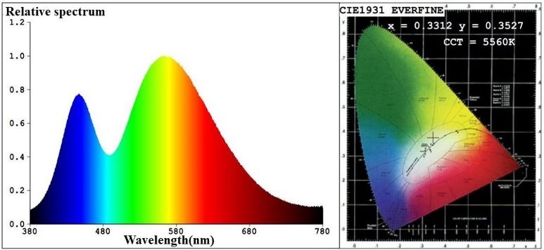
blocks the stray light to form a clear cutoff line. In our laboratory
laser headlamp without ellipsoid reflector (Figure 3) was design
Micromachines 2021, 12, 663
was also adopted in the integrated headlamp for the low4 ofbeam
16
fo
optical system.
romachines 2021, 12, 663
Double freeform surface lens (DFSL) has many advantages ov
Figure 3. Low beam system without an ellipsoid reflector.
Figure 3. Low beam system without an ellipsoid reflector.
faceDouble
lens.freeform
For example,
surface lensit(DFSL)
can achieve
has many an accurate
advantages over distribution
single freeform of lig
maticlens.
surface dispersion
For example, byit can
its achieve
inner an and outer
accurate freeform
distribution surfaces
of light [15]. The d
and suppress
chromatic dispersion by its inner and outer freeform surfaces [15]. The deflection factor C
C≤≤C1),
(0 ananimportant
≤ 1), important factorfactor
in DFSL,inisDFSL, is usedthe
used to represent toangular
represent theratio
deflection angular
freeform
of two freeform surfaces.
surfaces. It It is worth
is worth noting noting that
that θ, ϕ are θangle
zenith , ϕandare zenith
azimuth angle a
angle,
respectively, and α is the angle between the discrete points on the target plane and positive
Xspectively,
axis (Figure 4). and α angle
The ray’s is the
after angle between
passing through thefreeform
the inner discrete points
surface on the
could be
tive X axis (Figure 4). The
denoted as follows: ray’s angle after passing through the i
θ1 = Cθ0 + (1 − C )θ2
(1)
could be denoted as follows: ϕ1 = Cϕ + (1 − C )α
Figure
Figure 4. Sketch
4. Sketch of deflection
of the light the light deflection
of the asymmetric of thefreeform
double asymmetric double
surface lens. freeform
To construct the ADFSL, the mapping relationship between certain angle rays on
the target plane and discrete points of the target plane should be calculated. Figure 5
1 θ = Cθ + (1 − C )θ
shows the division of the target illumination area. To simplify the calculation and generate
0 2
qualified illumination distribution, the lighting zone is set as an ellipse and divided into I,
ϕ = Cϕ + (1 − C )α
II, III zones. E1, E2, E3 are the corresponding illuminances of zone I, II, III, respectively,
and the semi-major axis is a, and the semi-minor axis,1 b. Similarly, the semi-major and
semi-minor axes are equally divided into three parts, with ai , bi being the semi-major axis
To construct
and semi-minor axis of thethe ADFSL,
divided therespectively.
sub-ellipse, mapping Onrelationship
ce between
the other hand, the target
target plane and discrete points of the target plane should be calcu
the division of the target illumination area. To simplify the calculat
ified illumination distribution, the lighting zone is set as an ellipse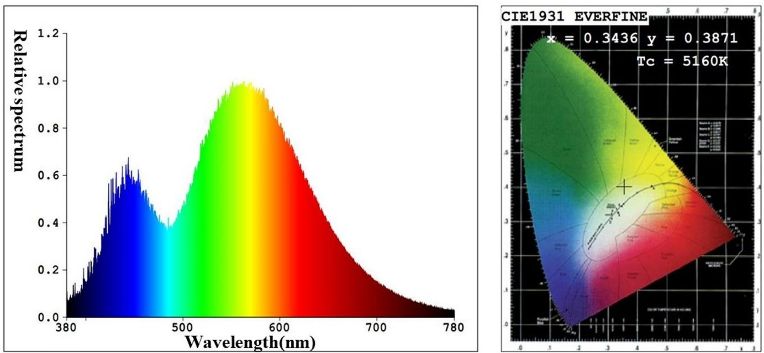
III zones. E1, E2, E3 are the corresponding illuminances of zone I, II, I
                               the semi-major axis is a, and the semi-minor axis, b. Similarly, the se
                               minor axes are equally divided into three parts, with ai , bi being
Micromachines 2021, 12, 663                                                                                         5 of 16
                               and semi-minor axis of the divided sub-ellipse, respectively. On the ot
                               illumination area is divided into n parts along the direction α , wh
                              illumination
                               between areaith ispart
                                                  divided
                                                       and     n parts
                                                          intothe      along theX
                                                                   positive     direction
                                                                                  axis. α, where αi is the angle between
                              ith part and the positive X axis.

                              Figure
                              Figure 5. Division of the target
                                         5. Division           plane
                                                          of the     for lowplane
                                                                   target   beam.                       for low beam.
                                    I0 is the central intensity of the LED source; I(θ ) , the intensity distribution of light
                              in the θ direction; θ, the angle between the emergent light and the optical axis; and the
                              relationship between I(θ ) and I0 can be expressed as follows:

                                                                                       I(θ ) = I0 cos θ                                                           (2)

                                   According to the conservation of energy, we obtain [30]
                                               R θ1                              1 αn
                                                                                  R                 a21 b12
                                         2π        0    I0 · cos θ · sin θdθ =   2 0     E1·      2 α + a sin2 α dα
                                                                                           b
                                                                                           1 cos           1
                                               R θ2                              1 αn
                                                                                  R                     a22 b22              a21 b12
                                         2π             I0 · cos θ · sin θdθ =        E2 ·                         −                        dα                    (3)
                                                   θ1                            2 0          b2 cos2 α+ a2 sin2 α   b1 cos2 α+ a1 sin2 α

                                               R θ3                              1 αn
                                                                                  R                        a23 b32                    a22 b22
                                         2π        θ2 I0 · cos θ · sin θdθ   =   2 0     E3·
                                                                                                   b3 cos2 α+ a3 sin2 α
                                                                                                                          −   b2 cos2 α+ a2 sin2 α
                                                                                                                                                         dα

                                    By solving the above integral equation, the mapping relationship between θi and the
                              illumination area on the target plane can be acquired.
                                    According to the conservation of energy, the relationship between the azimuth angle
                              ϕ j and α j can be expressed as follows:
                                  R θ 1 R ϕ j +1                                 1 α j +1
                                                                                  R                     a21 b12
                                   0               I0 · cos θ · sin θdθdϕ =      2 αj        E1·      2 α + a sin2 α dα
                                         ϕj                                                    b
                                                                                               1 cos           1
                                  R θ 2 R ϕ j +1                                 1 α j +1
                                                                                  R                         a22 b22              a21 b12
                                                   I0 · cos θ · sin θdθdϕ =               E2 ·                         −                        dα                (4)
                                   θ1    ϕj                                      2 αj             b2 cos2 α+ a2 sin2 α   b1 cos2 α+ a1 sin2 α

                                  R θ3 R ϕ j+1                                    1 α j +1
                                                                                   R                            a23 b32                    a22 b22
                                                    I0 · cos θ · sin θdθdϕ =                 E3·                              −                              dα
                                   θ2     ϕj                                      2 αj                 b3 cos2 α+ a3 sin2 α       b2 cos2 α+ a2 sin2 α

                                   By solving the above equation, the relationship between ϕ j and α j is obtained.
                                                                                 (
                                                                                       x(i,j) = ai cos α j
                                                                                                                                                                  (5)
                                                                                       y(i,j) = bi sin α j

                                    The coordinates of the points on the target plane can be calculated by Equation (5).
                              Then, we obtain the mapping relationship between the light emitting from the source and
                              the points on the target plane. Next, the profile of ADFL is calculated by iteration. The
                              initial points of the first and second freeform surfaces are set as L1 and L2, respectively.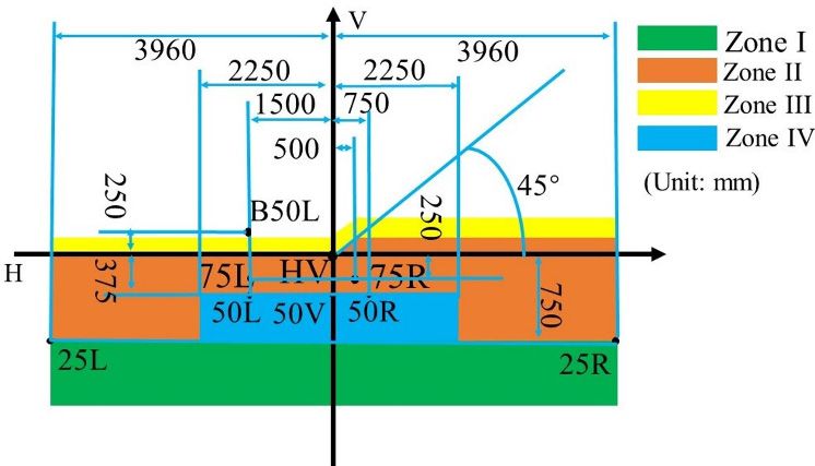
Micromachines 2021, 12, 663 6 of 16
After the initial points are given, the normal vector of the initial points can be obtained
according to the vector form of refraction law,
→ →
→ no out − nin In
N= → →
(6)
no out − nin In
Micromachines 2021, → → →
romachines 2021, 12,12,
663663 where In is the unit vector of the incident ray, Out is the unit vector of outgoing ray, N is
the normal vector, no is the refractive index in the outgoing space, and nin is the refractive
index in the incident space. All coordinates of the discrete points on the freeform surface
can be calculated by iteration of the normal vector, which stipulates that the intersection
the first
point of the and second
next incident rayfreeform surfaces
and the normal plane ofisthe
generated. Then,
last point is the by fixing
next point on the the va
the first and second freeform surfaces is generated. Then, by fixing th
changing the value of ϕ , the coordinates of the discrete points onBy
curve. The expression of the normal plane at any point can be obtained by Equation (6). both fre
changing theofvalue
fixing the value of , the
ϕ and changing ϕthevalue
coordinates ofcurve
of θ, the initial the discrete points
of the first and secondon both
can be surfaces
freeform acquired by iteration
is generated. Then, byoffixing
the normal
the value ofvector. Readers
θ and changing thecan
valuefind
of ϕ,the de
can
the be acquired
coordinates of the by iteration
discrete points on of
boththe normal
freeform surfacesvector.
process in reference 15. After importing the data to modeling software,
can be Readers
acquired by can
iterationfind th
th
process in
of the normal reference
vector. Readers15.
can After
find the importing
detailed iterationthe
the ADFSL can be obtained by lofting curve, as shown in Figure 6. data
process in to
[15].modeling
After importing software
the data to modeling software, the upper half of the ADFSL can be obtained by lofting
the ADFSL can be obtained by lofting curve, as shown in Figure 6.
curve, as shown in Figure 6.
Figure 6. The upper half of the double freeform surface lens.
Figure 6. The upper half of the double freeform surface lens.
FigureThe
6. The upperbaffle
curved half ofplate
the double
with 45freeform
degreessurface lens.to form the clear
is chosen
The curved baffle plate with 45 degrees is chosen to form the clear cutoff line, as
shown in Figure 7.
shown in Figure 7.
The curved baffle plate with 45 degrees is chosen to form the c
shown in Figure 7.
Figure
Figure 7. The
7. The bafflebaffle
plate. plate.
2.2. Optical System of the High Beam Mode
2.2.The
Optical System
high beam of theofautomobile
the Highheadlamp
Beam Mode is mainly used for bad road lighting since
Figure 7. The baffle plate.
it provides enough illumination on the target area [31]. In addition, the regulations require
The high beam of the automobile headlamp is mainly used for bad road
it provides enough illumination on the target area [31]. In addition, the regu
2.2.
theOptical System
target plane of the
center High
area withBeam Mode illumination. The test area of th
maximum
shownTheinhigh beam
Figure 8. of the automobile headlamp is mainly used for bad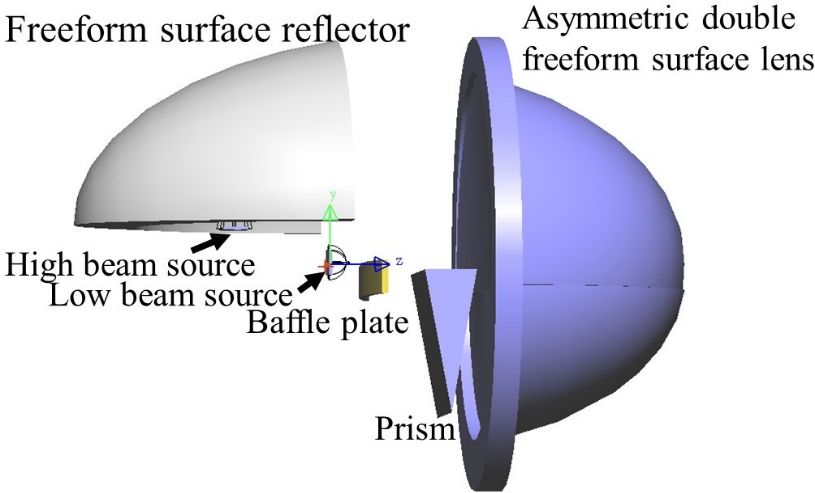
Figure 7. The baffle plate.
2.2. Optical System of the High Beam Mode
Micromachines 2021, 12, 663 The high beam of the automobile headlamp is mainly used 7 of 16 for ba
it provides enough illumination on the target area [31]. In addition, the
the target plane center area with maximum illumination. The test area
the target plane center area with maximum illumination. The test area of the high beam is
shown
shown in Figure
in Figure 8. 8.
Figure
Figure8. Test
8. points and regions
Test points andof the high beam.
regions of the high beam.
The traditional design uses an ellipsoidal reflector to focus the rays emitted from the
The part
source, while traditional design
of the rays emitted uses
from an ellipsoidal
the high beam source will reflector
be blocked to focus
by the low the ra
beam source due to the volume of the LED source. It will cause significant energy losses,
machines 2021, 12, 663
source,
as shown inwhile part
Figure 9a. of the
Therefore, therays emitted
construction from
in Figure 1 isthe high
adopted beam source
to improve light wi7
low beam
efficiency source due
and illumination. Rays to the from
emitted volume
the highof thesource
beam LEDfocus
source. It on
on a point will
Z caus
axis by the freeform surface reflector, as shown in Figure 9b.
losses, as shown in Figure 9a. Therefore, the construction in Figure 1 is
light efficiency and illumination. Rays emitted from the high beam sou
on Z axis by the freeform surface reflector, as shown in Figure 9b.
(a) (b)
Figure
Figure 9. (a) 9. (a) Integrated
Integrated headlamp
headlamp based
based onon ellipsoidal reflector
ellipsoidal reflectorandand
(b) sketch of the freeform
(b) sketch reflector. reflector.
of the freeform
Due to the symmetry of the reflector, only half of the freeform surface reflector was
Due to theAnsymmetry
designed. ofgiven
initial point is the and
reflector, only
the normal halfof of
vector thethe freeform
initial surface
point can be reflector
obtained
according to the vector form of the reflection law, which can be expressed
designed. An initial point is given and the normal vector of the initial point can b as
tained according to the vector form of the→reflection → law, which can be expressed as
→ out − In
N= (7)
out
→ →
In − In
−out
N =
→ → out − In →
where In, Out are the unit vectors of the incident ray and outgoing ray, respectively, and N
is
normal
the vector. The initial curve and profile of the freeform surface reflector can be
In , Out
whereobtained by anare the unit
iteration vectors of the incident ray and outgoing ray, respecti
process.
Freeform surface reflector converges rays emitted from the source to another focus
and N is the normal vector. The initial curve and profile of the freeform surface refl
on the Z axis. Therefore, the focus on the Z axis can be seen as a light source without
can bevolume
obtained that by
does annot
iteration
block theprocess.
rays from the low beam source and will illuminate the
Freeform
target plane.surface
Similar reflector converges
to the process of low beamrays emitted
design, fromspot
the lighting theofsource
the high to another f
beam
is set as an ellipse, whose semi-major axis and semi-minor axis are
on the Z axis. Therefore, the focus on the Z axis can be seen as a light sourceequally divided into m wit
parts. Accordingly, ai , bi are the semi-major and semi-minor axes of ith part, respectively,
volume that does not block the rays from the low beam source and will illuminat
target plane. Similar to the process of low beam design, the lighting spot of the high b
is set as an ellipse, whose semi-major axis and semi-minor axis are equally divided in
parts. Accordingly, ai , bi are the semi-major and semi-minor axes of ith part, re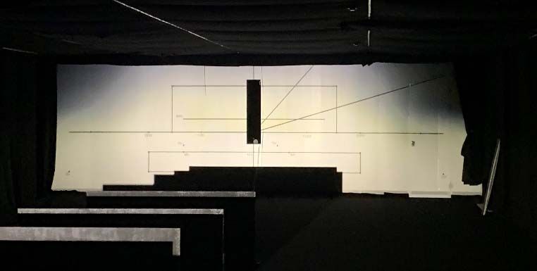
where In , Out are the unit vectors of the incident ray and outgoin
and N is the normal vector. The initial curve and profile of the freefo
Micromachines 2021, 12, 663 can be obtained by an iteration process. 8 of 16
Freeform surface reflector converges rays emitted from the sou
on the Z axis. Therefore, the focus on the Z axis can be seen as a l
0 ≤ i ≤ m. At the same time, the target plane is also divided into n parts along the α
volume that does not block the rays from the low beam source and
direction, αi is the angle between ith part and the X axis, and then the target plane is
targetinto
divided plane.
m × nSimilar
lattices, asto theinprocess
shown Figure 10.of low beam
According to thedesign, the lighting sp
energy conservation,
we can obtain the mapping relations.
is set as an ellipse, whose semi-major axis and semi-minor axis are eq
ai a, i+b1 bi i+are
!
2 2 2 2
I(θ,ϕparts. Accordingly, the−semi-major anddαsemi-minor (8) axes
1 j +1 a i bi
Z θ Z ϕ Z α
i +1 j +1
1
) dθdϕ = E0 ·k i ·
θi ϕj 2 αj bi+1 cos α + ai+1 sin α bi cos α + ai sin2 α
2 2 2
tively, 0 ≤ i ≤ m. At the same time, the target plane is also divided into
where E0 ·ki is the illumination value, and ki is the illuminance control factor on the
direction,
ith α i the
part. Generally, is closer
the angle
to the originalbetweenpoint, ith part the
the greater and theofXtheaxis,
value ki . I (θ,and
ϕ) then
isdivided
the intensity
into m × n oflattices,
distribution the light focusedas shownby theinfreeform
Figuresurface reflector. After
10. According to the e
calculating Equation (8), the mapping relationship can be acquired, and the profile of the
we can
lower obtain
half of the ADFSLtheismapping
calculated byrelations.
the normal vector iteration.
Figure
Figure10. Division of the target
10. Division planetarget
of the for highplane
beam. for high beam.
Similar to the low beam lens construction method, the whole ADFSL can be built in
Micromachines 2021, 12, 663 8 ofare
the modeling software. As shown in Figure 11, the diameter and thickness of the lens 16
θi +1 ϕ j +1 64 mm and 30 mm, 1 respectively.
α j +1 2
a b 2
ab2 2
θ ϕ
i j
I (θ ,ϕ ) dθ dϕ = α j beam0 lensi αconstruction
2 low
Similar to the
E k
+biδ+1 cos α
2
i +1 i +1
α + cos
method, 1
0 +I 2
sin
ai +1Ithe
2 α
−
2 whole ADFSL
i i
bi coscan2 αbe+built
ai sinin
2
α
sin( ) = n sin( )· 0 (9)
the modeling software. As shown in2 Figure 11, the cos I1 +2 I 2 and thickness of the lens are
2 diameter
where
64 mm andE30
0∙kmm,
i is the illumination value, and ki is the illuminance control f
respectively.
Generally, the closer to the original point, the greater the value of th
intensity distribution of the light focused by the freeform surface refle
ing Equation (8), the mapping relationship can be acquired, and the
half of the ADFSL is calculated by the normal vector iteration.
Figure
Figure 11.
11. The
Theasymmetric
asymmetric double
double freeform
freeform surface
surface lens.
lens.
I1′ + I 2
cos
α +δ α 2
sin( ) = n sin( ) (9)
2 2 cos 1 I 2′
I +
2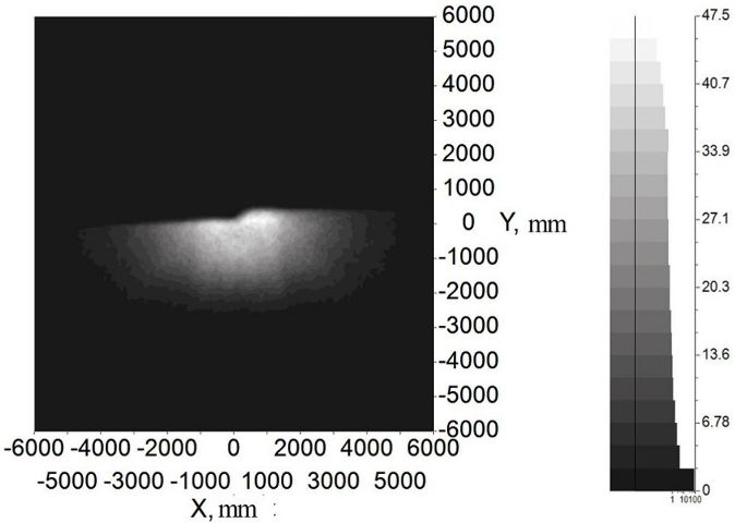
sin( ) = n sin( ) 2
2 2 cos I1 + I 2′
2
Micromachines 2021, 12, 663 Although DFSL can reduce chromatic dispersion on9 ofthe 16 targ
serious chromatic dispersion at the edge due to the large deflection a
pattern with a stable color distribution, a prism was added to the op
Although DFSL can reduce chromatic dispersion on the target plane, there is still
the deflection
serious angle at
chromatic dispersion ofthethe ADFSL.
edge due to theFigure 12 shows
large deflection anobtain
angle. To optical
a lightpath in
pattern with a stable color distribution, a prism was added to the optical system to reduce
can deflect rays based on refraction law, and the deflection angle
the deflection angle of the ADFSL. Figure 12 shows an optical path in the prism. The prism
and outgoing
can deflect ray
rays based onis δ . Formula
refraction law, and the(9)deflection
presents anglethe calculation
between the incidentof the d
and outgoing
prism [32].ray is δ. Formula (9) presents the calculation of the deflection angle of the
prism [32].
Figure 12. Optical path in the prism.
Figure 12. Optical path in the prism.
3. Simulation
After calculation and optimization, the whole system of the integrated headlamp is
3. Simulation
introduced into the optical simulation software LightTools [33], as shown in Figure 13. The
volume of the whole system is 91 × 64 × 64 mm3 , which is smaller than all the separately
After
designed calculation
headlamp systems. Theand optimization,
low beam source placed atthe whole
the origin is KWsystem of the in
H4L531.TE
introduced
of OSRAM company intoandthe opticalwith
6R brightness simulation software
1300 lm luminous LightTools
flux is selected [34]. On the[33], as
Micromachines 2021, 12, 663 other hand, the high beam source placed at a focus of the freeform surface reflector is KW
The volume
H4L531.TE and 7Rof the whole
brightness system
with 1500 is 91
lm luminous flux×is64 × 64Low
selected. mm and, high
3 which is sma
beam
rately designed
sources comply with theheadlamp
ECE R48 and ECE systems. The [28,29].
R128 regulations low beam source placed
H4L531.TE of OSRAM company and 6R brightness with 1300 lm lum
[34]. On the other hand, the high beam source placed at a focus o
reflector is KW H4L531.TE and 7R brightness with 1500 lm luminou
and high beam sources comply with the ECE R48 and ECE R128 reg
Figure13.13.
Figure Optical
Optical system
system of theof the integrated
integrated headlamp
headlamp in software.
in simulation simulation software.
Before the simulation, the freeform surface reflector is set as an aluminum all
a reflectivity of 90% and the lens material is PMMA with a refractive index of 1
baffle plate is set as a perfect absorber to absorb all rays that hit it. The exact illum
values on key points and the specified regions in the prescribed area can be rea
software. The simulation results are shown in the figures and tables below.
Figures 14 and 15 show the illumination and color distribution of the low b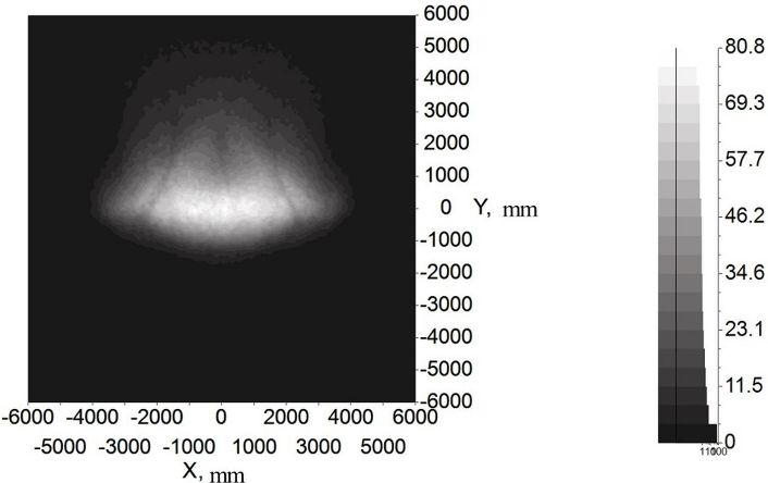
Figure 13. Optical system of the integrated headlamp in simulation software.
Figure 13. Optical system of the integrated headlamp in simulation software.
Before the simulation, the freeform surface reflector is set as an al
Before the simulation, the freeform surface reflector is set as an al
Micromachines 2021, 12, 663 a reflectivity of 90% and the lens material is PMMA with 10 a ofrefractiv
16
a reflectivity of 90% and the lens material is PMMA with a refractiv
baffle plate is set as a perfect absorber to absorb all rays that hit it. Th
baffle plate is set as a perfect absorber to absorb all rays that hit it. Th
values on key points and the specified regions in the prescribed area
valuesBeforeonthe key points
simulation, and the
the freeform specified
surface reflector isregions in the prescribed
set as an aluminum alloy with a area
software.
reflectivity Theand
of 90% simulation results
the lens material is PMMA arewith
shown in the
a refractive indexfigures and
of 1.49. The tables b
baffle
software.
plate isFigures
The simulation
set as a perfect absorber
results arethat
shown in the illuminance
figures and tables b
14 and 15toshow
absorb the
all rays hit it. The exact
illumination values
and color distribution o
on key Figures
points and 14 and 15regions
the specified showinthe illumination
the prescribed area canand color
be read in thedistribution
software. o
spectively.
The simulation Figure
results are 16 shows
shown in the the illumination
figures and tables below. distribution of the hig
spectively. Figure 16 shows the illumination distribution of the hig
shows the14color
Figures and 15distribution of a high
show the illumination beam
and color with a of
distribution prism,
the lowand
beam, Figure
shows theFigure
respectively. color 16 distribution of a high
shows the illumination beamofwith
distribution a beam.
the high prism, and17aFigure
Figure
distribution withoutofaa prism. Tables 1 and 2Figure
show the simulated illu
distribution
shows without a prism.
the color distribution high beamTables 1 and
with a prism, and 2 show 17b the
showssimulated
the color illu
the targetwithout
distribution plane of low
a prism. and
Tables high
1 and beams,
2 show respectively.
the simulated illuminance values on the
the target
target plane ofplane
low andof highlow and
beams, high beams, respectively.
respectively.
Figure
Figure 14. 14. The illumination
The illumination distributiondistribution
of low beam.
of low beam.
Figure 14. The illumination distribution of low beam.
Figure
Figure The color
15. 15. Thedistribution of low beam. of
color distribution
low beam.
Figure 15. The color distribution of low beam.25R ≥2
75R ≥15 41.50
50R
Zone I ≥12
≤2E * 40.48
50VZone III ≥6 ≤0.7 35.08
25LZone IV ≥2 ≥3 5.22
Micromachines 2021, 12, 663 11 of 16
25R ≥2 5.67
E * is the actual measurement of the value at point 50R.
Zone I ≤2E * √
Zone III ≤0.7 √
Zone IV ≥3 √
E * is the actual measurement of the value at point 50R.
Figure 16. The illumination distribution of high beam with prism.
Figure
Figure16. The
16. illumination distribution distribution
The illumination of high beam with
ofprism.
high beam with prism.
(a) (b)
Figure
Figure17.
17.(a)
(a)The
The color distributionof
color distribution ofhigh
highbeam
beamwith
witha prism
a prism and
and (b)(b) without
without a prism.
a prism.
Table 1. Simulated illuminance values of low beam on the target plane.
Point on Target Plane Required Illuminance in Lux Simulated illuminance in Lux
HV (a) ≤0.7 0.28 (b)
B50L ≤0.4 0.00
Figure 17.75L
(a) The color distribution
≤12 of high beam with a6.50
prism and (b) witho
50L ≤15 13.36
75R ≥15 41.50
50R ≥12 40.48
50V ≥6 35.08
25L ≥2 5.22
25R ≥2 5.67
√
Zone I ≤2E * √
Zone III ≤0.7 √
Zone IV ≥3
E * is the actual measurement of the value at point 50R.Micromachines 2021, 12, 663 12 of 16
Table 2. Simulated illuminance values of high beam on the target plane.
Point on Target Plane Required Illuminance in Lux Simulated Illuminance in Lux
Emax ≥48 and ≤240 80.80
HV ≥0.8 Emax 74.81
√
0–1125L, 1125R ≥24 √
0–2250, 2250R ≥6
Figures 14 and 15 indicate that the integrated headlamp system with a single ADFSL
could ensure the quality of the low beam. The illumination width of the low beam can reach
12 m, which can provide a large angle of view for drivers. Furthermore, the cutoff line with
the blue edge does not appear, which means that the inherent problem of the cutoff line
with the blue edge in traditional projection designs can be solved by this method. The color
temperature of the low beam is stable on the target plane, and the color on the target plane
is close to white. As shown in Table 1, the simulation values of the low beam fully meet the
requirements of ECE R112 regulations; Figure 16 shows that the illumination distribution
of the high beam can comply with the requirements of ECE R112 regulations. Furthermore,
the highest value of the high beam is 80.8 lux, providing sufficient illumination when the
road lighting is poor. Figure 17 shows the color distribution of the high beam. The color
distribution with a prism is more stable, as compared to the color distribution without a
prism, which means that adding a prism to the optical path can largely suppress chromatic
dispersion on the edge. Table 2 demonstrates that the simulation values of the high beam
satisfy the requirements of ECE R112 regulations. In short, the light shape of the low beam
and high beam and simulation values of the key points fully comply with the requirements
of ECE R112; Moreover, the chromatic dispersion can be largely suppressed by using a new
integrated optical system.
Here, we must present a simple analysis of the installation error. The error of the low
beam and high beam source position mounting is ±0.3 mm and 0.5 mm, respectively. In
other words, when position error is greater than the above values, the performance will
no longer satisfy the ECE R112 regulations. Therefore, proper installment of the optical
elements is very important for achieving optimal performance.
4. Experiment
To study the illumination performance of the experiment, the optical samples were
processed and assembled according to the results of the optical simulation software, and
the GO-HD5 automobile lighting test system was used for testing the illuminance values
of the key points and specified regions. According to ECE R112 regulations, the test starts
after the light source is steady. The lighting spot of the low beam and color temperature test
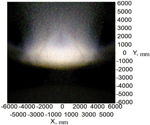
of the point 50 V are shown in Figure 18, and the lighting spot of the high beam and color
temperature test of the point HV are shown in Figure 19. The test illumination values of the
low beam and high beam measurement screens are shown in Tables 3 and 4, respectively.
From Figure 18a, there is a straight cutoff line with no stray light above, and the color
temperature is stable on the measuring screen. Slight chromatic dispersion appears near
the cutoff line, which is different from the simulation results. Additionally, it still meets
the ECE regulations. Compared with the traditional low beam, the chromatic dispersion
near the cutoff line is much slighter. The test results of illuminance were slightly different
from the simulations, due to the slight error of the shield’s place and the absorption of
mechanical objects. However, all illuminance values at the required points can fit with the
regulations. According to ECE regulations, the color test results for the 50 V point must
be within the white light range. The color test result at point 50 V is 5160 K, as shown in
Figure 18b, and is quite qualified. The low beam lighting spot has a smooth transition that
provides drivers with visual comfort.Micromachines 2021, 12, 663 13 of 16
(a)
(b)
Figure 18. Figure 18. (a) The
(a) The lighting spotlighting spot
and (b) test and (b)
results test results
of color of color
of the point 50 V of
forthe
lowpoint
beam.50V for
low beam.
Table 3. Tested illuminance values of low beam on the target plane.
Point on Target Plane Required Illuminance in Lux Tested Illuminance
HV ≤0.7 0.42
B50L ≤0.4 0.00
75L ≤12 7.36
50L ≤15 13.25
75R ≥15 32.32
50R ≥12 30.26
(a)
50V ≥6 34.26
25L ≥2 6.32
25R ≥2 6.85
Zone I ≤2E * √
Zone III ≤0.7 √
Zone IV ≥3 √
E * is the actual measurement of the value at point 50R.
(b)
Figure 19.Figure
(a) The19. (a) Thespot
lighting lighting spot
and (b) and
test (b) test
results of results
color ofofthe
color of HV
point the point HVbeam.
for high for
high beam.Micromachines 2021, 12, 663 14 of 16
Table 3. Tested illuminance values of low beam on the target plane.
Point on Target Plane Required Illuminance in Lux Tested Illuminance in Lux
HV ≤0.7 0.42
B50L ≤0.4 0.00
75L ≤12 7.36
50L ≤15 13.25
75R ≥15 32.32
50R ≥12 30.26
50V ≥6 34.26
25L ≥2 6.32
25R ≥2 6.85
√
Zone I ≤2E * √
Zone III ≤0.7 √
Zone IV ≥3
E * is the actual measurement of the value at point 50R.
Table 4. Tested illuminance values of high beam on the target plane.
Point on Target Plane Required Illuminance in Lux Tested Illuminance in Lux
Emax ≥48 and ≤240 70.36
HV ≥0.8 Emax 65.34
√
0–1125L, 1125R ≥24 √
0–2250L, 2250R ≥6
It can be inferred from Figure 19a and Table 4 that the lighting spot is nearly elliptic
and the central area is the brightest, which meets the ECE regulations. The color of the high
beam is almost white, indicating that adding a prism could reduce chromatic dispersion
at the edge of the target area and stabilize the color temperature. Similar to the test low
beam results, the high beam test results in Table 4 are lower than the simulation results.
The maximum illuminance of the high beam is 70.36 lux, less than simulation results but
still much greater than the regulation requires, and can provide sufficient illumination
for the ground. Similarly, the color test results for the HV point must be within the white
light range. The color test result of the HV point is 5560 K, as shown in Figure 19b, which
complies with the regulations.
5. Discussion
According to the simulation and experimental results, it can be found that both
illuminance values of the required points and the color temperature distributions are
qualified. The comparison of the new integrated headlamp system with the traditional
headlamp system is shown in Table 5.
Table 5. The comparison of the new integrated headlamp with traditional headlamp.
Chromatic Dispersion
Items Volume Cost Low Beam High Beam Cutoff Line
on the Target Plane
Slight
New integrated
Small Low Qualified Qualified chromatic Slight
headlamp system
dispersion
Traditional A little serious
projection Large High Qualified Qualified chromatic A little serious
headlamp system dispersion
The volume of the new integrated LED headlamp is 91 × 64 × 64 mm3 , much smaller
than that of the traditional headlamp. The ADFSL has a diameter of 64 mm, as large as the
traditional low beam lens, which means saving space for installing the high beam systemMicromachines 2021, 12, 663 15 of 16
and its cooling system. Compared with the high beam without prism, the new headlamp
with ADFSL and prism has a more uniform color distribution due to the light deflection
of the prim. Both low and high beams are qualified. Since the new integrated headlamp
has only one optical system, it costs less than the traditional headlamp with two optical
systems. By using an asymmetric double freeform surface lens, the cutoff line of the new
integrated headlamp has less chromatic dispersion than that of the traditional headlamp
using a single freeform surface or aspheric surface lens, providing comfortable lighting for
oncoming drivers. These advantages make the new integrated headlights acceptable in the
headlamp market.
6. Conclusions
We proposed a method to design the asymmetric double freeform surface lens and
the integrated LED headlamp optical system. The construction algorithms of the optical
elements were presented in detail. Simulation and experimental results show that a good
light pattern can be obtained with the selected source, and the values of key points and
specified regions can fully comply with the standards of ECE R112, 48, and 128. Moreover,
color uniformity on the target plane is improved by the freeform surface lens and the
prism. The volume of the whole optical system is smaller than that of the traditional
headlamp, saving space to install other electronic devices safely, such as distance sensors,
to help drivers gain better control of the distances between vehicles. Moreover, the freeform
surface optical system has high compactness and manufacturing feasibility.
Author Contributions: The work presented here was carried out in collaboration between all authors.
Conceptualization and methodology, H.Z., D.L. and H.W.; validation and analysis, writing, H.Z. and
Y.W.; supervision, H.W. All authors have read and agreed to the published version of the manuscript.
Funding: This work was funded by Science and Technologies Plan Projects of Guangdong Province
(Nos.2017B010112003, 2020B010171001), and Guangzhou Municipal Science and Technology Plan
Projects (Nos.201604046021, 201905010001), and Science and Technology Development Special Fund
Projects of Zhongshan City (Nos.2019AG014,2019AG042,2020AG023).
Data Availability Statement: The data presented in this study are included in the article.
Conflicts of Interest: The authors declare no conflict of interest.
References
1. Schubert, E.; Kim, J. Solid-state light sources getting smart. Science 2005, 308, 1274–1278. [CrossRef]
2. Georlette, V.; Bette, S.; Brohez, S.; Pérez-Jiménez, R.; Point, N.; Moeyaert, V. Outdoor Visible Light Communication Channel
Modeling under Smoke Conditions and Analogy with Fog Conditions. Optics 2020, 1, 259–281. [CrossRef]
3. Liang, W.L.; Su, G.J. Design of a high-efficiency train headlamp with low power consumption using dual half-parabolic aluminized
reflectors. Appl. Opt. 2018, 57, 1305–1314.
4. Tsai, C.-Y. Design of free-form reflector for vehicle LED low-beam headlamp. Opt. Commun. 2016, 372, 1–13. [CrossRef]
5. Ge, A.; Wang, W.; Du, Z.; Qiu, P.; Wang, J.; Cai, J. High-energy-efficiency optical system for an LED-based headlamp architecture.
Appl. Opt. 2013, 52, 8318–8323. [CrossRef]
6. Brick, P.; Schmid, T. Automotive headlamp concepts with low-beam and high-beam out of a single LED. Proc. SPIE 2011,
8170, 817008.
7. Choi, H.; Choe, S.; Ryu, J. Optical Design of a Novel Collimator System with a Variable Virtual-Object Distance for an Inspection
Instrument of Mobile Phone Camera Optics. Appl. Sci. 2021, 11, 3350. [CrossRef]
8. Cvetkovic, A.; Dross, O.; Chaves, J.; Benitez, P.; Miñano, J.C.; Mohedano, R. Etendue-preserving mixing and projection optics for
high-luminance LEDs, applied to automotive headlamps. Opt. Express 2006, 14, 13014–13020. [CrossRef]
9. Dross, O.; Cvetkovic, A.; Chaves, J.; Benítez, P.; Miñano, J.C. LED headlight architecture that creates a high quality beam pattern
independent of LED shortcomings. SPIE-Int. Soc. Opt. Eng. 2005, 5942, 59420D.
10. Domhardt, A.; Rohlfing, U.; Weingaertner, S.; Klinger, K.; Kooß, D.; Manz, K.; Lemmer, U. New design tools for LED headlamps.
SPIE 2008, 7003, 70032C.
11. Hsieh, C.-C.; Li, Y.-H.; Hung, C.-C. Modular design of the LED vehicle projector headlamp system. Appl. Opt. 2013, 52, 5221–5229.
[CrossRef]
12. Chu, S.-C.; Chen, P.-Y.; Huang, C.-Y.; Chang, K.-C. Design of a high-efficiency LED low-beam headlamp using Oliker’s compound
ellipsoidal reflector. Appl. Opt. 2020, 59, 4872–4879. [CrossRef] [PubMed]
13. Ge, P.; Wang, X.; Li, Y.; Wang, H. A projective LED low-beam headlamp of motorbikes. SPIE 2014, 9298, 92981U.Micromachines 2021, 12, 663 16 of 16
14. Wang, H.; Wang, X.; Li, Y.; Ge, P. Design of a newly projected light-emitting diode low-beam headlamp based on microlenses.
Appl. Opt. 2015, 54, 1794–1801. [CrossRef]
15. Luo, D.; Ge, P.; Liu, D.; Wang, H. A combined lens design for an LED low-beam motorcycle headlight. Light. Res. Technol. 2017,
50, 456–466. [CrossRef]
16. Wu, H.; Zhang, X.; Ge, P.; Yu, J. A high-efficiency freeform reflector for a light-emitting diode low-beam headlamp. Light. Res.
Technol. 2016, 48, 1005–1016. [CrossRef]
17. Qiu, P.; Ge, A.; Wang, J.; Cai, J.; Zhu, L.; Du, Z. Design of an LED-based headlamp low-beam system using combined prisms.
Light. Res. Technol. 2014, 47, 248–253. [CrossRef]
18. Whang, A.; Jhan, K.C.; Chao, S.M.; Chen, G.W.; Chou, C.H.; Lin, C.M.; Chang, C.M.; Chen, K.Y.; Lai, Y.L. An innovative vehicle
headlamp design based on a high-efficiency LED light pipe system. Lighting Res. Technol. 2013, 47, 210–220. [CrossRef]
19. Chen, F.; Wang, K.; Qin, Z.; Wu, D.; Luo, X.; Liu, S. Design method of high-efficient LED headlamp lens. Opt. Express 2010, 18,
20926–20938. [CrossRef]
20. Ma, C.-T.; Chou, K.-H.; Chen, Y.-Y.; Whang, A.J.-W.; Chen, K.-Y. Design and optimization of automotive headlamps based on
projection system with double ellipsoidal reflector. Photonics Eur. 2010, 7717, 77170M.
21. Liou, Y.C.; Wang, W. Lighting design of headlamp for adaptive front-lighting system. J. Chin. Inst. Eng. 2007, 30, 411–422.
[CrossRef]
22. Zhu, Z.; Wei, S.; Liu, R.; Hong, Z.; Zheng, Z.; Fan, Z.; Ma, D. Freeform surface design for high-efficient LED low-beam headlamp
lens. Opt. Commun. 2020, 477, 126269. [CrossRef]
23. Hung, C.-C.; Fang, Y.-C.; Huang, M.-S.; Hsueh, B.-R.; Wang, S.-F.; Wu, B.-W.; Lai, W.-C.; Chen, Y.-L. Optical design of automotive
headlight system incorporating digital micromirror device. Appl. Opt. 2010, 49, 4182–4187. [CrossRef] [PubMed]
24. Wu, H.; Zhang, X.; Ge, P. Modular design of a high-efficiency LED headlamp system based on freeform reflectors. Opt. Laser
Technol. 2015, 72, 79–85. [CrossRef]
25. Boroczki, A.; Horvath, C.; Panyik, T. Three-Mode Integrated Headlamp. U.S. Patent No. US20090251915A1, 6 December 2011.
26. Rice, L.M.; Tessnow, T. Headlamp Featuring Both Low-Beam and High-Beam Outputs and Devoid of Moving Parts. U.S. Patent
No. US8894257B2, 25 November 2014.
27. United Nations Economic Commission for Europe, Vehicle Regulations, Reg112. Available online: http://www.unece.org/
fileadmin/DAM/trans/main/wp29/wp29regs/r112r1e.pdf (accessed on 4 May 2021).
28. United Nations Economic Commission for Europe, Vehicle Regulations, Reg48. Available online: https://unece.org/fileadmin/
DAM/trans/main/wp29/wp29regs/2013/R048r9e.pdf (accessed on 4 May 2021).
29. United Nations Economic Commission for Europe, Vehicle Regulations, Reg128. Available online: https://unece.org/fileadmin/
DAM/trans/main/wp29/wp29regs/2015/R128e.pdf (accessed on 4 May 2021).
30. Ge, P.; Wang, X.; Li, Y.; Wang, H. Reflective Optics Design for an LED High Beam Headlamp of Motorbikes. Sci. World J. 2015,
2015, 503171. [CrossRef]
31. Owens, D.A.; Wood, J.M.; Owens, J.M. Effects of age and illumination on night driving: A road test. Hum. Factors J. Hum. Factors
Ergon. Soc. 2007, 49, 1115–1131. [CrossRef]
32. Sun, W.-S.; Tien, C.-L.; Chen, J.-A.; Lin, J.-S. Optical design for a cost-effective low-beam headlamp with a white light LED. Opt.
Quantum Electron. 2020, 52, 1–17. [CrossRef]
33. Software LightTools. Available online: https://www.synopsys.com/optical-solutions/lighttools.html (accessed on 4 May 2021).
34. KW H4L531.TE of OSRAM. Ave: https://www.osram.com/ecat/OSLON%C2%AE%20Black%20Flat%20KW%20H4L531.TE/
com/en/class_pim_web_catalog_103489/prd_pim_device_2190830/ (accessed on 4 May 2021).You can also read