Bulletin #1182 Installation & User Guide Models 620L & 622L Linear Rope Gripper
←
→
Page content transcription
If your browser does not render page correctly, please read the page content below

L I N E A R   R O P E   G R I P P E R ™   6 2 0 L / 6 2 2 L   B U L L E T I N   # 1 1 8 2

    Bulletin #1182
    Installation & User Guide
    Models 620L & 622L
    Linear Rope Gripper®

REV D, 3-Nov-20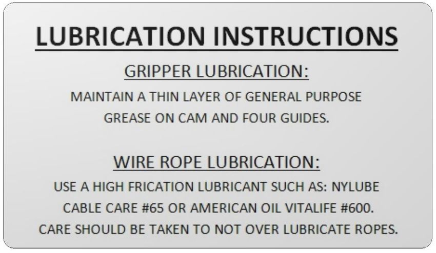
L I N E A R   R O P E   G R I P P E R   ®   6 2 0 L / 6 2 2 L   B U L L E T I N   # 1 1 8 2

REV D; 3-Nov-20                                                                                         i

L I N E A R   R O P E   G R I P P E R   ®   6 2 0 L / 6 2 2 L   B U L L E T I N   # 1 1 8 2

                Installation & User Guide
                      Bulletin #1182

        MODEL 620L                                                            MODEL 622L
        LINEAR ROPE                                                           LINEAR ROPE
          GRIPPER®                                                              GRIPPER®

                               © Hollister-Whitney Elevator Co. LLC
                                   #1Hollister-Whitney Parkway
                                         Quincy, IL 62305
                              Phone 217.222.0466 • Fax 217.222.0493
                                             11/3/2020

REV D; 3-Nov-20                                                                                         ii
L I N E A R   R O P E   G R I P P E R ™   6 2 0 L / 6 2 2 L   B U L L E T I N   # 1 1 8 2

                                                WARNING
This installation and user guide is intended for qualified and authorized elevator personnel
ONLY. For your safety and the safety of others, do not attempt ANY procedure that you
are not qualified and authorized to perform. Recommended procedures must be done in
accordance with the applicable rules of the latest edition of the National Electrical Code;
the latest edition of ASME A17.1; and all governing local codes. Every attempt has been
made to ensure that this guide is accurate and up-to-date. Hollister-Whitney Elevator Co.
LLC assumes no liability for consequences resulting from any error or omission. Please
notify Hollister-Whitney Elevator Co. LLC regarding any difficulties with this guide

                                                WARNING
Keep hands clear of moving parts forces created can crush fingers.

REV D, 3-Nov-20                                                                                          iii
L I N E A R     R O P E    G R I P P E R ™       6 2 0 L / 6 2 2 L     B U L L E T I N      # 1 1 8 2

Contents
     1   User Guide ................................................................1-1
            1.1 Features ..............................................................................1-1
                  1.1.1   Mounting to Channel Guidelines...................................................1-3
            1.2 Environmental Considerations ............................................1-6
            1.3 Storage ...............................................................................1-6
                  1.3.1   Short Term Storage .....................................................................1-6
                  1.3.2   Long Term Storage ......................................................................1-6
            1.4 Lang Lay Considerations ....................................................1-6
        2         Installation .................................................................2-7
            2.1     Safety ..................................................................................2-7
            2.2     Verification ..........................................................................2-7
            2.3     Planning ..............................................................................2-7
            2.4     Locating the Assembly ........................................................2-8
            2.5     Mounting ...........................................................................2-11
            2.6     Testing ..............................................................................2-14
            2.7     Lining Wear-In...................................................................2-15
        3         Service ......................................................................3-1
            3.1 Safety ..................................................................................3-1
            3.2 Lining Replacement ............................................................3-1
                  3.2.1   Excessive Lining Wear .................................................................3-2
                  3.2.2   Non-Excessive Lining Wear .........................................................3-2
            3.3 Lubrication Instructions .......................................................3-3
            3.4 Testing All Circuits ..............................................................3-3
            3.5 Suggested Controller Circuits .............................................3-4
                  3.5.1   GRC1 Description ........................................................................3-5
                  3.5.2   GRC2 Description ........................................................................3-5
                  3.5.3   DZC1 Description.........................................................................3-6
                  3.5.4   DZC2 Description.........................................................................3-7
                  3.5.5   Gripper Self-Test..........................................................................3-7
        4         Operation ..................................................................4-1
            4.1     Normal Operation................................................................4-1
            4.2     Over-Speed.........................................................................4-1
            4.3     Over-Speed Reset ..............................................................4-1
            4.4     Unintended Motion ..............................................................4-2
            4.5     Unintended Motion Reset....................................................4-2
            4.6     Smart Gripper .....................................................................4-2
            4.7     Manual Opening..................................................................4-2
        5         Warning Labels .........................................................5-1

REV D; 3-Nov-20                                                                                                            iv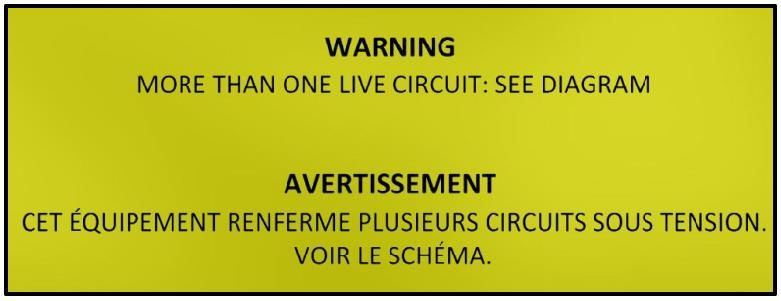
L I N E A R   R O P E   G R I P P E R ™   6 2 0 L / 6 2 2 L   B U L L E T I N   # 1 1 8 2

              5.1 High Pressure Applied Warning Label ................................5-1
              5.2 Movable Shoe Warning Label .............................................5-1
              5.3 More Than One Live Circuit Warning Label ........................5-2
          6       Troubleshooting Guide .............................................6-1
              6.1 LED Troubleshooting Guide ................................................6-1
              6.2 Wiring Schematic ................................................................6-2
          7       Service Parts ............................................................7-1

List of Figures

Figure 1 - Key Components .............................................................................. 1-3

Figure 2 - New Installation................................................................................. 1-4

Figure 3 - Existing Installation ........................................................................... 1-5

Figure 4 – Important Notice – Lang Lay Ropes ................................................. 1-6

Figure 5 - Safety Set Screw .............................................................................. 2-8

Figure 6 - Removable Shoe .............................................................................. 2-8

Figure 7 - Vertical Ropes................................................................................. 2-10

Figure 8 - Angled Ropes ................................................................................. 2-10

Figure 9 - Mounting Footprints ........................................................................ 2-10

Figure 10 - Stationary Shoe Contact ............................................................... 2-11

Figure 11 - Rope Distribution .......................................................................... 2-12

Figure 12- Movable Shoe ................................................................................ 2-12

Figure 13 - Connecting Arms .......................................................................... 2-12

Figure 14 – REMOVE TAG BEFORE WIRING ............................................... 2-13

Figure 16 - Connecting Arms .......................................................................... 2-14

Figure 15 - Connecting Arms .......................................................................... 2-14

REV D; 3-Nov-20                                                                                                    v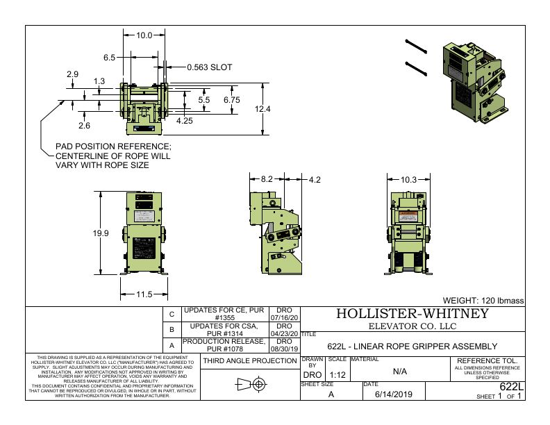
L I N E A R   R O P E    G R I P P E R ™    6 2 0 L / 6 2 2 L   B U L L E T I N   # 1 1 8 2

Figure 17 – IMPORTANT – Lining Wear-In ..................................................... 2-15

Figure 18 – IMPORTANT – Wear-In Line........................................................ 2-15

Figure 19 - Connecting Arms .......................................................................... 2-16

Figure 20 - Shim Locations ............................................................................. 2-17

Figure 21 – Lubrication Instructions .................................................................. 3-3

Figure 22 - Circuit – I ......................................................................................... 3-5

Figure 23 - Circuit – II ........................................................................................ 3-6

Figure 24 - Circuit –III ........................................................................................ 3-6

Figure 25 – Manual Opening ............................................................................. 4-3

Figure 26 – High Pressure Applied Warning Label ........................................... 5-1

Figure 27 – Movable Shoe Warning Label ........................................................ 5-2

Figure 28 – More than one Live Circuit Warning Label ..................................... 5-2

Figure 29 – LED Troubleshooting Guide ........................................................... 6-1

Figure 30 – Wiring Schematic ........................................................................... 6-2

REV D; 3-Nov-20                                                                                                         vi

L I N E A R   R O P E   G R I P P E R ™   6 2 0 L / 6 2 2 L   B U L L E T I N   # 1 1 8 2

                                             Section

                                               1
1 User Guide

1.1 Features
The 620L and 622L Rope Gripper® protects against ascending car over-speed and/or
unintended car movement. The Rope Gripper® can prevent the car from moving in the
event of;

   •   The car falling up or down accidentally
   •   The car leaving the floor with the door(s) open
   •   Ropes slipping traction on traction wheel

The Rope Gripper® provides powerful, steady pressure on the hoist ropes. By using easily
replaceable non asbestos linings, the hoist ropes will not be damaged. While the braking
engages the hoist ropes with a quick, but powerful grip, the Rope Gripper ® will not put
excessive stress on the machine or drive sheave when the unit is installed properly.

There is no need for a separate hydraulic or air unit, resulting in a smaller footprint.

The electromagnetic clutch releases on removal of power and is designed to protect
internal construction from possible damage.

The electric linear actuator and electromagnetic clutch features allows an automatic reset
when power is restored.

The Rope Gripper® is equipped with intelligent self-monitoring functionality and will not
complete the safety circuit if any internal fault is detected.

REV D, 3-Nov-20                                                                                          1-1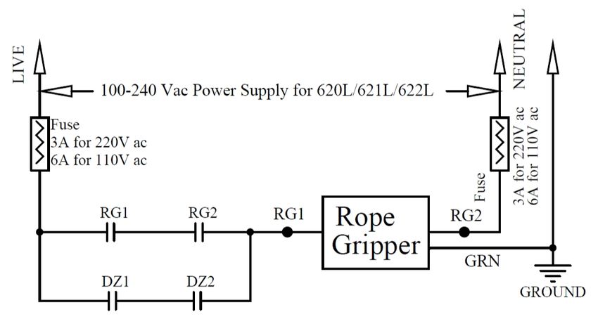
L I N E A R R O P E G R I P P E R ™ 6 2 0 L / 6 2 2 L B U L L E T I N # 1 1 8 2
Table 1 - Specifications
ROPE GRIPPER® MODEL
620L 622L
MAX. OUT TO inch 5.25 6.5
OUT OF CABLES mm 133.3 165
inch ± 3 (6 Total)
DOOR ZONE
mm ± 76.2 (152.4 Total)
CLOSING TIME sec. 0.300
1A, 100~240V ac, 2A, 100~240V ac,
POWER SUPPLY
1PH, 50/60Hz 1PH, 50/60Hz
CONTACT RATINGS 5A, 250V ac, 5A, 30V dc
fpm 350 600
RATED SPEED m/s 1.78 3.05
MAXIMUM RATINGS
m/m 107 183
fpm 402 690
ROPE GRIPPER
m/s 2.04 3.51
TRIPPING SPEED
1:1 ROPING
m/m 1231 210
lbs 2560 5000
CAR RATED LOAD
kg 1161 2268
TOTAL SYSTEM lbs 12070 18600
LOAD kg 5475 8437
600
MINIMUM
lbs 1500
RATINGS
CAR RATED LOAD
kg 272 680
CAR & CWT lbs 2280 6000
MASS kg 1034 2722
fpm 250 400
RATED SPEED m/s 1.27 2.03
MAXIMUM RATINGS
m/m 76 122
fpm 303 459
ROPE GRIPPER
m/s 1.54 2.33
TRIPPING SPEED
2:1 ROPING
m/m 92 140
lbs 5120 10000
CAR RATED LOAD
kg 2322 4536
TOTAL SYSTEM lbs 24140 38000
LOAD kg 10950 17237
1500
MINIMUM
lbs 2500
RATINGS
CAR RATED LOAD
kg 680 1134
CAR & CWT lbs 6000 8000
MASS kg 2722 3629
fpm 87 150
RATED SPEED m/s 0.44 0.76
MAXIMUM RATINGS
m/m 27 46
fpm 110 189
ROPE GRIPPER
m/s 0.56 0.96
TRIPPING SPEED
4:1 ROPING
m/m 33 58
lbs 10240 20000
CAR RATED LOAD
kg 4644 9072
TOTAL SYSTEM lbs 48280 76000
LOAD kg 21900 34473
3000
MINIMUM
lbs 5000
RATINGS
CAR RATED LOAD
kg 1361 2268
CAR & CWT lbs 12000 16000
MASS kg 5443 7257
REV D; 3-Nov-20 1-2
L I N E A R R O P E G R I P P E R ™ 6 2 0 L / 6 2 2 L B U L L E T I N # 1 1 8 2
Figure 1 - Key Components
1.1.1 Mounting to Channel Guidelines
When mounting the Rope Gripper® to a channel framework, it must withstand upward and
downward forces according to Table 3 and meet applicable codes.
Any mounting channel framework must be sufficiently sized to securely hold the Rope
Gripper® and elevator while preventing any sliding. The traction machine must also be
prevented from sliding. See Figure 2 - New Installation and Figure 3 - Existing Installation
for suggested machine room mounting configurations.
NOTE -
HOLLISTER-WHITNEY ALSO OFFERS MACHINES WITH BUILT-IN FACTORY
MOUNTS FOR ROPE GRIPPERS®. PLEASE CONTACT YOUR HOLLISTER-
WHITNEY SALES ASSOCIATE FOR MORE DETAILS.
REV D; 3-Nov-20 1-3L I N E A R R O P E G R I P P E R ™ 6 2 0 L / 6 2 2 L B U L L E T I N # 1 1 8 2
Figure 2 - New Installation
REV D; 3-Nov-20 1-4L I N E A R R O P E G R I P P E R ™ 6 2 0 L / 6 2 2 L B U L L E T I N # 1 1 8 2
Figure 3 - Existing Installation
REV D; 3-Nov-20 1-5L I N E A R R O P E G R I P P E R ™ 6 2 0 L / 6 2 2 L B U L L E T I N # 1 1 8 2
1.2 Environmental Considerations
A Hollister-Whitney Rope Gripper® is designed to perform in a tolerant machine space.
The machine space working temperature should be held between 35°F & 104°F, (1.7°C &
40°C) and humidity should be held to an average of 90% non-condensing.
1.3 Storage
1.3.1 Short Term Storage
• For short-term storage, place the Rope Gripper® in a warm, dry and clean
environment.
• Protect the Rope Gripper® from harsh weather conditions and temperature
variations that can lead to condensation.
• Protect the Rope Gripper® from dust, dirt, and moisture.
1.3.2 Long Term Storage
• For long-term storage, place the Rope Gripper® in a sealed, waterproof enclosure
with a dehydrating packet that is sized for the enclosure volume and humidity level.
• Follow the same instructions as outlined in Section 1.3.1 - "Short Term Storage".
1.4 Lang Lay Considerations
An Important Notice label is located on the Rope Gripper® Figure 4 – Important Notice –
Lang Lay Ropes. If your elevator is equipped with Lang Lay ropes Hollister-Whitney
recommends that code compliant rope retention be installed on all wheels in accordance
with the latest ASME A17.1/CSA B44 revisions.
Figure 4 – Important Notice – Lang Lay Ropes
REV D; 3-Nov-20 1-6L I N E A R R O P E G R I P P E R ™ 6 2 0 L / 6 2 2 L B U L L E T I N # 1 1 8 2
Section
2
2 Installation
2.1 Safety
• Wear proper PPE (Personal Protective Equipment).
• Inspect tools to ensure they are in good condition and proper working order.
• Read and understand all instructions prior to proceeding.
• Follow standard elevator industry and governing safety requirements.
2.2 Verification
Verify all components are present and that the Rope Gripper® assembly can be installed.
It may be necessary to fully verify the assembly by checking the following:
• Confirm the contract and part numbers match your numbers on your order.
• Compare the received unit to the assembly drawings included in this document.
• Determine if the received assembly is correct by comparing its capabilities to those
required for the project.
2.3 Planning
• Determine the rope drop location (matching the existing drop or refer to applicable
job layouts) by using plum lines or laser means.
• Confirm that the assembly will have adequate clearance when positioned in line
with the required rope drop.
• Prior to the installation of the assembly, plan and prepare for the electrical and/or
conduit routing.
• Ensure that electrical routing will not interfere with the operation, maintenance, or
removal of the assembly.
NOTE -
ITEMS SUCH AS CONDUIT, FITTINGS, EXTERNAL WIRING, AND MOUNTING
HARDWARE ARE NOT PROVIDED.
REV D; 3-Nov-20 2-7L I N E A R R O P E G R I P P E R ™ 6 2 0 L / 6 2 2 L B U L L E T I N # 1 1 8 2
2.4 Locating the Assembly
• The initial state of the Rope Gripper®, from the factory, is an open (loaded) state.
Check and confirm the safety set screws are installed deep enough to hold the
rotating shaft in the LOADED (open) position Figure 5.
Engage the safety
set screws.
Figure 5 - Safety Set Screw
• Remove the four E-Clips, and both connecting arms. Remove the movable shoe
assembly Figure 6.
a) Remove the circlip
b) Remove the
connecting arms
c) Remove the movable
shoe assembly
Figure 6 - Removable Shoe
REV D; 3-Nov-20 2-8L I N E A R R O P E G R I P P E R ™ 6 2 0 L / 6 2 2 L B U L L E T I N # 1 1 8 2
• Check that the shim configuration of the movable plate assembly matches the wire
rope specifications. The shim configuration for different wire rope specifications are
shown in
• Table 2 – Initial Shim Configurations.
Table 2 – Initial Shim Configurations
620L / 622L
Rope Sizes Outer Shims Inner Shims
Lining Wear Spacer +
Nominal MM Decimal Spacer Shims between
Excess Spacers on
(Inch) Range Equivalent Block and Shoe
Back of Block
9 0.354
3/8” 1/8" 1/32 + 2 x 1/16 + 1/8"
10 0.394
7/16” 11 0.433 1/16" + 1/8" 1/32 + 1/16 + 1/8"
12 0.472
1/2” 2 x 1/16 + 1/8" 1/32 + 1/8"
13 0.512
9/16” 14 0.551 1/16" + 2 x 1/8" 1/32 + 1/16"
15 0.591
5/8” 2 x 1/16 + 2 x 1/8" 1/32"
16 0.630
NOTE -
THE ROPE GRIPPER® WAS SHIPPED FROM THE FACTORY SHIMMED FOR 5/8
INCH ROPES.
• Place the assembly on mounting channels as shown in the examples noted in
Figure 2 - New Installation, or Figure 3 - Existing Installation.
• Move the Rope Gripper® into position, aligning the unit with the ropes as shown in
Figure 7 then mark the mounting holes. If the wire ropes are at an angle, set the
Rope Gripper® parallel with the ropes Figure 8 before marking the holes.
• Verify the assembly will not interfere with elevator equipment (machine frame,
traction or deflector sheave, machine beams, etc.) or any other obstructions.
REV D; 3-Nov-20 2-9L I N E A R R O P E G R I P P E R ™ 6 2 0 L / 6 2 2 L B U L L E T I N # 1 1 8 2
Figure 7 - Vertical Ropes Figure 8 - Angled Ropes
• Use the assembly base to mark the mounting locations for the bolts. A field
template (not included) can also be made from cardboard, plywood or Masonite for
locating the mounting holes per Figure 9 - Mounting Footprint.
• Remove the assembly or template and drill the required 39/64” dia. mounting holes.
Figure 9 - Mounting Footprints
REV D; 3-Nov-20 2-10L I N E A R R O P E G R I P P E R ™ 6 2 0 L / 6 2 2 L B U L L E T I N # 1 1 8 2
2.5 Mounting
• Attach Rope Gripper® to mounting channels with the recommended bolts per Table
3. Do not fully tighten the bolts yet.
Table 3 - Mounting Specifications
MODEL # APPROXIMATE GRADE 5 MOUNTING BOLTS REFERENCE
UP & DOWN FORCE (Approximate Torques) DRAWINGS
620L 2000 lbs. 1/2" UNC @ 74 ft.-lbs. See Appendix (a)
622L 4000 lbs. 1/2" UNC @ 74 ft.-lbs. See Appendix (b)
NOTE -
MOUNTING MUST CONFORM TO LOCAL, STATE, AND APPLICABLE CODES.
• Position the Rope Gripper® so that the stationary shoe lining lightly touches all the
ropes from top to bottom.
The friction plate lightly
touches the hoist ropes.
Figure 10 - Stationary Shoe Contact
• Make sure Rope Gripper® is squarely aligned, and centered side to side as much
as possible, with the ropes. Misalignment may cause uneven and/or excessive
lining wear.
REV D; 3-Nov-20 2-11L I N E A R R O P E G R I P P E R ™ 6 2 0 L / 6 2 2 L B U L L E T I N # 1 1 8 2
Make sure that the left and
right edges of the stationary
shoe are evenly distributed
with the hoist ropes.
Figure 11 - Rope Distribution
• Securely fasten Rope Gripper® mounting bolts. Make sure they are torqued per
Table 3.
• Check rope alignment. Make sure all ropes touch the stationary shoe lining evenly.
• Reinstall the movable shoe assembly. Reinstall the connecting arms with
chamfered edges facing the inside of the Rope Gripper® with the wear-in line sticker
facing out and secure the four circlips (and washers if applicable).
Install the movable
shoe assembly
Install connecting
arm and replace
the circlips
Figure 12- Movable Shoe Figure 13 - Connecting Arms
REV D; 3-Nov-20 2-12L I N E A R R O P E G R I P P E R ™ 6 2 0 L / 6 2 2 L B U L L E T I N # 1 1 8 2
• Connect terminals RG1, RG2, RG5, RG7 and RG11 to elevator control. Check
control diagram for proper connection. See Figure 22. Connect the earth ground
to the grounding screw located in the electrical enclosure.
IMPORTANT-
It may not be necessary to connect RG11 to elevator control with an additional wire back
to the controller. The temporary tag shown below in Figure 14 – REMOVE TAG BEFORE
WIRING is initially located over the connections on a new Rope Gripper®. Remove the tag
before wiring and review the information. If “RG2” is connected to the
COMMON/RETURN or “RG5”, then you can connect “RG11” to “RG9A”. This can be
done with a permanent connection inside of the Rope Gripper ® electrical enclosure. If
“RG2” is not connected to the COMMON/RETURN of “RG5”, then connect “RG11” to the
COMMON/RETURN of “RG5”. Typically, this requires an additional wire routed back to
the controller. Please consult your controller schematic and with your elevator controller
manufacture for more details or if you are unsure if “RG2” is connected to the
COMMON/RETURN of “RG11”.
Figure 14 – REMOVE TAG BEFORE WIRING
• Make sure controller safety circuit is active and clear for running. Turn test switch
ON. The motor may run momentarily prior to energizing the electromagnetic clutch.
• When the electromagnetic clutch is energized, loosen the two security set screws a
turn or two. Confirm that the Rope Gripper® is being held open.
• Remove security set screws. Once removed, store the set screws in the two
threaded holes provided in the gearbox base plate.
REV D; 3-Nov-20 2-13L I N E A R R O P E G R I P P E R ™ 6 2 0 L / 6 2 2 L B U L L E T I N # 1 1 8 2
NOTE -
SECURITY SET SCREWS MUST BE COMPLETELY REMOVED WHEN ROPE
GRIPPER® ACTIVATES TO PREVENT THE GRIPPER FROM FAILING TO SET OR
CAUSE DAMAGE TO THE UNIT.
• Unit is now ready for the required testing and lining wear-in.
2.6 Testing
• Make sure controller safety circuit is active and clear for running. Turn test switch
ON. The Rope Gripper® should be in or go to the ready, open (LOADED) position
(NOT clamping the ropes).
• Turn test switch to OFF. This should activate the Rope Gripper ®, clamping the
ropes. Be sure that while clamping the ropes, the Elevator Can Run switch
contacts on the Rope Gripper® stop or prevent power from being applied to the
motor and machine brake.
Excessive wear
microswitch
adjustment
Brake ready
microswitch
adjustment
Elevator can
run switch
Figure 16 - Connecting Arms Figure 15 - Connecting Arms
• Turn test switch ON. Rope Gripper® should reload (re-open).
REV D; 3-Nov-20 2-14L I N E A R R O P E G R I P P E R ™ 6 2 0 L / 6 2 2 L B U L L E T I N # 1 1 8 2
2.7 Lining Wear-In
• The Rope Gripper® will not function properly until the linings have been worn in. A
label has been placed on the Rope Gripper® to notify personal of the importance of
lining wear in Figure 17 – IMPORTANT – Lining Wear-In.
Figure 17 – IMPORTANT – Lining Wear-In
• A line has been marked on the side wall of the Rope Gripper® to aid in the Wear-In
process and a label is located on the Rope Gripper® arms indicating the Rope
Gripper® arms must match of cover the wear in line Figure 18 – IMPORTANT –
Wear-In Line.
Figure 18 – IMPORTANT – Wear-In Line
NOTE -
AT THIS POINT IN THE PROCEDURE, THIS LINE IS WELL ABOVE THE CONNECTING
ARM AND WILL BE MET OR COVERED BY THE CONNECTING ARM DURING THE
WEAR-IN PROCESS (SEE FIGURE 1 FOR LOCATIONS OF CONNECTING ARM AND
WEAR-IN LINE).
• Make sure test switch is ON.
• Run the car at a slow or inspect speed. Keeping hands clear of all equipment use
caution to wipe down the ropes to remove any dirt and/or excess oil and grease
from top to bottom.
• Jump terminals RG5 to RG7, preferably at the controller, and run the empty car in
slow speed in the direction that the machine will pull the ropes thru the Rope
Gripper® (typically DOWN). When the car is up to that speed, turn the test switch
OFF. The Rope Gripper® will clamp the ropes with a light pressure and ropes will
begin to wear grooves in the linings.
REV D; 3-Nov-20 2-15L I N E A R R O P E G R I P P E R ™ 6 2 0 L / 6 2 2 L B U L L E T I N # 1 1 8 2
Corner
Shaft
Figure 19 - Connecting Arms
• As the linings wear in, the rotating shaft will move up the cam slot and around the
corner of the cam noted above (Figure 19), and the connecting arms (see Figure 1 -
Key Components) will move up the side wall and begin to match or line up with the
wear-in line marked on the side wall.
NOTE -
IT MAY TAKE SEVERAL CAR RUNS TO COMPLETE LINING WEAR-IN.
• Once the rotating shaft has turned the corner and the wear-in line is matched or
covered, stop the car and REMOVE THE JUMPER FROM RG5 TO RG7.
CAUTION
FAILURE TO REMOVE THE JUMPER WILL CAUSE UNSAFE CONDITIONS.
If the lining wear-in is not completed after the grooves in the linings have reached
approximately 1/16” (1.5 mm) deep, spacer shims (Figure 20) can be moved from
between the shaft support blocks and moveable shoe to the outside of the support block
to allow the rotating shaft to just turn the corner and move up the cam to near the wear-in
line. Refer to Table 2 – Initial Shim Configurations for recommended initial spacer and
shim set-up
NOTE -
THE ROPE GRIPPER® WAS SHIPPED FROM THE FACTORY SHIMMED FOR 5/8 INCH
ROPES.
REV D; 3-Nov-20 2-16L I N E A R R O P E G R I P P E R ™ 6 2 0 L / 6 2 2 L B U L L E T I N # 1 1 8 2
CAUTION
BEFORE CHANGING SPACERS, INSTALL SECURITY SET SCREWS TO
PREVENT UNINTENDED ROPE GRIPPER® ACTIVATION, WHICH COULD
LEAD TO SEVERE PERSONAL INJURY AND/OR DAMAGE TO THE UNIT.
Figure 20 - Shim Locations
REV D; 3-Nov-20 2-17L I N E A R R O P E G R I P P E R ™ 6 2 0 L / 6 2 2 L B U L L E T I N # 1 1 8 2
Section
3
3 Service
3.1 Safety
• Wear proper PPE (Personal Protective Equipment).
• Inspect tools to ensure they are in good condition and proper working order.
• Read and understand all instructions prior to servicing.
• Follow standard elevator industry and governing safety requirements.
3.2 Lining Replacement
The linings will wear, especially after multiple high-speed stops. When clamping, the
rotating shaft will move towards the upper end of the cam as the linings wear. Near the
end of the cam, the excessive wear micro switch Figure 16 will open and the Rope
Gripper® will not automatically reopen (reload).
In this case you must inspect the linings, and decide whether the spacer shims should be
adjusted, or the linings should be replaced. This will depend on whether the grooves in
the linings are more or less than 3/16” (4.75mm) deep. To inspect linings for wear, first
reopen the Rope Gripper® using Method 1 or 2 below.
1. Turn test switch off. On PC Board, move jumper J1 to J2. Turn test switch on;
Rope Gripper® will reload electrically. Once in the open position, install the security
set screws so they touch the rotating shaft. Return jumper on J2 to J1. Or;
2. Turn test switch off. Refer to section 4.7 Manual Opening. Only open as far as is
necessary to install security set screws. Opening Rope Gripper® further will
damage Rope Gripper®. Once in the open position, install the security set screws
so they touch the rotating shaft and remove any wrenches.
IMPORTANT-
Use wrenches to open Rope Gripper® only as far as is necessary to install security set
screws. Opening Rope Gripper® further could damage Rope Gripper®. Once in the
REV D; 3-Nov-20 3-1L I N E A R R O P E G R I P P E R ™ 6 2 0 L / 6 2 2 L B U L L E T I N # 1 1 8 2
open position, install the security set screws so they touch the rotating shaft and
remove any wrenches.
CAUTION
BEFORE CHANGING SHOES OR SPACERS, INSTALL SECURITY SET
SCREWS TO PREVENT UNINTENDED ROPE GRIPPER® ACTIVATION,
LEADING TO SEVERE PERSONAL INJURY AND/OR DAMAGE TO THE
UNIT.
3.2.1 Excessive Lining Wear
If lining wear is excessive, greater than 3/16” (4.75 mm), linings should be replaced.
Remove both connecting arms by removing 4 circlips (and washer if applicable). Remove
moveable shoe assembly. Remove screw from top of each lining assembly and remove
linings by unhooking them at the bottoms. It may be necessary to loosen the mounting
bolts to tip Rope Gripper® to allow access to the stationary shoe. Refer to Table 2 – Initial
Shim Configurations for initial spacer and shim set-up to use with new linings. When
linings have been replaced, follow the Installation procedure and the Lining Wear-In
procedure.
3.2.2 Non-Excessive Lining Wear
If lining wear is not excessive, less than 3/16” (4.75 mm), spacer shims (Figure 20) can be
moved from the back side of the shaft support blocks to between the shaft support blocks
and moveable shoe. Loosen the bolts that hold the blocks to the movable shoe, move a
1/8” spacer shim from the outer side to the rope side under the blocks and tighten bolts.
Addition of shims between the block and the shoe will move the shoe closer to the ropes
and lower the position of the rotating shaft toward the bottom end of the cam when
clamping.
When replacements are complete, turn the test switch ON and carefully remove the
security set screws, being sure the electromagnetic clutch holds. Follow the procedures
described earlier to ensure that the rotating shaft will be around the corner at the bottom of
the cam (and connecting arm position matches or covers the wear-in line marked on the
side wall) when gripping the ropes.
IMPORTANT-
After replacing the linings or after adjusting the spacer shims it is important to test the
Rope Gripper® to ensure the Rope Gripper® is functioning properly and the rotating
shaft if around the corner.
REV D; 3-Nov-20 3-2L I N E A R R O P E G R I P P E R ™ 6 2 0 L / 6 2 2 L B U L L E T I N # 1 1 8 2
3.3 Lubrication Instructions
It is important to maintain a thin layer of general-purpose grease on the cam and guides.
A lubrication instructions label is also continentally located on the Rope Griper® Figure 21
– Lubrication Instructions.
Figure 21 – Lubrication Instructions
3.4 Testing All Circuits
The following three tests should be made while the car is running in slow speed in both
the up and down directions. During each test the Rope Griper® should:
A. Grab the ropes
B. Stop the car
C. Open the control safety circuits disconnecting power to the motor and
machine brake
1) Turn the Rope Gripper® test switch OFF. Observe A, B, and C above.
2) With the car in the door zone, open the door or open the door lock circuit, then
open the door zone circuit, and observe A, B, and C above.
NOTE -
THE CONTROLLER’S SAFETY CIRCUITS SHOULD REQUIRE A MANUAL RESET
BEFORE THE ROPE GRIPPER® REOPENS.
3) Manually open the governor over-speed switch and observe A, B, and C above.
REV D; 3-Nov-20 3-3L I N E A R R O P E G R I P P E R ™ 6 2 0 L / 6 2 2 L B U L L E T I N # 1 1 8 2 NOTE - THE GOVERNOR WILL REQUIRE A MANUAL RESET AFTER THIS TEST. THE CONTROLLER’S SAFETY CIRCUITS SHOULD THEN REQUIRE A MANUAL RESET BEFORE THE ROPE GRIPPER® REOPENS. 3.5 Suggested Controller Circuits NOTE - THE FOLLOWING DESCRIBES CIRCUITS TO MEET CODE REQUIREMENTS AND PREVENT NUISANCE SHUTDOWNS. THE CONTROLS CIRCUIT CAN ALSO BE CONFIGURED SO THAT THE ROPE GRIPPER® ALSO RESPONDS TO OTHER ERRORS. Both the B44 and A17.1-2000 Codes and more recent codes require new circuitry for activation of the Rope Gripper®. It is the controller manufacturer’s responsibility to provide proper circuitry that meets all applicable codes and laws for operating this device. The function of the Rope Gripper® when applied is to clamp the ropes and stop the car. We recommend that the Rope Gripper® is activated when an over-speed occurs or when the car leaves the floor (door zone) with the doors open (hoist way door unlocked and/or the car gate switch open). If the doors happen to be open while the car is between floors, the Rope Gripper® need not be activated. It is suggested that a manual reset of the Rope Gripper ® require a minimum of 30 seconds of constant pressure activation, to allow the mechanic resetting the Rope Gripper ® to quickly react to an unsafe condition. In other words, it is recommended that the reset control act as a constant pressure switch for the first ten seconds, before latching in the run condition after ten seconds. It is suggested that if the elevator controller has a monitor function for the machine brake, that the Rope Gripper® be activated immediately on sensing a stuck brake condition, rather than waiting for unintended motion to occur. The suggested circuits shown in Figure 22 and Figure 23 activate the Rope Gripper® by opening contacts RG1, RG2, DZ1, and DZ2. Relay coils RG1, RG2, DZ1 and DZ2 are controlled by the governor over-speed switch (GOS) and function blocks GRC1, GRC2, DZC1, and DZC2, respectively. REV D; 3-Nov-20 3-4
L I N E A R   R O P E   G R I P P E R ™   6 2 0 L / 6 2 2 L   B U L L E T I N   # 1 1 8 2

3.5.1 GRC1 Description

If the car is not in the door zone when main line power turns “ON”, or when switching from
“Inspection” to “Normal Operation”, or when resetting the governor over-speed switch;
allow a time interval, signal the door closure, and when the car gate or door interlock
contact makes, energize RG1.

Anytime the car is in the door zone (“Inspection” or “Normal Operation”), RG1 is de-
energized when both the car gate contact and door interlock contact are opened. Should
the car now leave the door zone (unintended motion), power to the Rope Gripper® is
removed and the Rope Gripper® is activated. In the door zone, when the car gate contact
or door interlock contact is made, energize RG1. If the car should leave the door zone
with RG1 energized, then Rope Gripper® activation is prevented. RG1 should remain
energized even if both the car and hoist way doors are opened while between floors.
When the car is in the door zone again, RG1 should function as above.

3.5.2 GRC2 Description

Redundant circuits are required by the 2000 A17.1 and B44 Codes. Circuits for RG2
function identical to RG1 except separate logic for the timing function, door locks, gate
switch and door zone should be used. DZC1 logic could be used for circuits of RG1 and
DZC2 for circuits of RG2. (See NOTE in Figure 24)

                                           Figure 22 - Circuit – I

REV D; 3-Nov-20                                                                                          3-5
L I N E A R R O P E G R I P P E R ™ 6 2 0 L / 6 2 2 L B U L L E T I N # 1 1 8 2
Figure 23 - Circuit – II
Figure 24 - Circuit –III
NOTE -
IF FORCE GUIDED RELAYS ARE USED FOR RG1, RG2, DZ1, AND DZ2, USE THIS
DIAGRAM.
3.5.3 DZC1 Description
DZ1 is energized in the door zone and de-energized outside of the door zone (See Figure
24’s Note). Maximum door zone is +/-3 inches [6 inches Total].
REV D; 3-Nov-20 3-6L I N E A R R O P E G R I P P E R ™ 6 2 0 L / 6 2 2 L B U L L E T I N # 1 1 8 2
3.5.4 DZC2 Description
• Circuits for DZ2 function are identical to DZ1 except a separate door zone signal is
utilized.
If the above circuits (Figure 24) do not make contact when required, the elevator must be
prevented from running. If other types of relays are used, circuits must prove that contacts
from RG1, RG2, DZ1 and DZ2 are functioning properly and when a failure is detected the
elevator must be prevented from running.
3.5.5 Gripper Self-Test
The Rope Gripper® is equipped with self-monitoring functionality to ensure that it
functioned properly. It is recommended that the controller periodically activate the Rope
Gripper® to test proper functioning. It is suggested the controller self-test be done with
the elevator doors closed and the normal service brake “set”. If the Rope Gripper®
functions properly, the controller will reopen the Rope Gripper® and the elevator will go
back into normal operation. It is recommended that this self-test occur at regular intervals
such as every three months with the car at the top of the hoist way at a low traffic time in
accordance with all standard and local elevator regulations and protocols. Please contact
your controller manufacture for further implementation considerations.
REV D; 3-Nov-20 3-7L I N E A R R O P E G R I P P E R ™ 6 2 0 L / 6 2 2 L B U L L E T I N # 1 1 8 2
Section
4
4 Operation
4.1 Normal Operation
Power to the Rope Gripper® is constantly maintained. When in the door zone DZ1 and
DZ2 provide power to the Rope Gripper®. RG1 and RG2 energize when the doors close.
As the car leaves the floor DZ1 and DZ2 de-energize, power to the Rope Gripper® is
maintained through RG1 and RG2. When approaching a new floor DZ1 and DZ2 again
energize, when the doors open RG1 and RG2 de-energize.
4.2 Over-Speed
When an over-speed is detected, the governor over-speed switch opens; additional over-
speed can be detected by use of an encoder or tachometer that detects the speed of the
elevator. (Not the motor or worm shaft of a geared elevator.) When detected, relays RG1,
RG2, DZ1 and DZ2 de-energize. This removes power from the Rope Gripper®, clamping
the ropes and stopping the car.
4.3 Over-Speed Reset
Over-speed reset is accomplished by resetting the governor over-speed switch and the
elevator control circuits. Refer to and follow the controller manufacturer’s instructions for
Rope Gripper® reset.
IMPORTANT-
The code requires that the Rope Gripper® be manually reset if it is triggered by fault. It is
intended that a qualified technician inspect for and correct any malfunction before the car
is placed back into service. A dangerous situation can be produced if a Rope Gripper® is
manually reset without first correcting the cause of the fault. E.g.: If there has been a
brake failure that has not been corrected, when the Rope Gripper® is reset, it is very likely
that the car will fall either up or down.
REV D; 3-Nov-20 4-1L I N E A R R O P E G R I P P E R ™ 6 2 0 L / 6 2 2 L B U L L E T I N # 1 1 8 2
4.4 Unintended Motion
When at the floor with the doors open, relays RG1 and RG2 are de-energized and relays
DZ1 and DZ2 are energized. If the car leaves the floor, DZ1 and DZ2 de-energize,
removing power from the Rope Gripper®, clamping the ropes and stopping the car.
4.5 Unintended Motion Reset
Unintended motion reset is accomplished through elevator control circuits. Refer to and
follow the control manufacturer’s instructions for Rope Gripper® reset.
IMPORTANT-
The code requires that the Rope Gripper® be manually reset if it is triggered by fault. It is
intended that a qualified technician inspect for and correct any malfunction before the car
is placed back into service. A dangerous situation can be produced if a Rope Gripper® is
manually reset without first correcting the cause of the fault. E.g. if there has been a
brake failure that has not been corrected, when the Rope Gripper® is reset, it is very likely
that the car will fall either up or down.
4.6 Smart Rope Gripper
The Rope Gripper® is equipped with intelligent self-monitoring functionality and will not
complete the safety circuit if any internal fault is detected. If you find that the Rope
Gripper® is not giving the controller a signal that it is safe to run consult the LED
Troubleshooting Guide Figure 29 – LED Troubleshooting Guide to aid in truoblshooting
procedures.
4.7 Manual Opening
CAUTION
USE CAUTION WHEN MANUALLY OPENING THE GRIPPER. THE
SPRINGS APPLY GREAT FORCE REQUIRING CONSIDERABLE TORQUE
TO ROTATE THE BALL SCREW WHEN MANUALLY OPENING. ENSURE
TOOLS ARE PROPERLY SECURED TO SHAFT AND TOOLS ARE
CONTROLLED WITH A FIRM STEADY GRIP.
During a power failure the Rope Gripper® will activate. When power is restored the Rope
Gripper® will automatically reload and put the elevator back into service.
REV D; 3-Nov-20 4-2L I N E A R R O P E G R I P P E R ™ 6 2 0 L / 6 2 2 L B U L L E T I N # 1 1 8 2
If the car is to be moved during a power outage, manually open the Rope Gripper® as
follows:
1. Confirm the Rope Gripper® power switch to OFF.
2. Confirm machine brake is functioning properly (preventing car movement).
3. Remove the electrical covers so that the end of the ball screw shaft is accessible.
4. Locate the two 10 mm rachet wrenches that were provided with the Rope Gripper®.
5. Place one 10 mm rachet wrench on the end of the ball screw on the top of the
Rope Gripper® to act as a holding wrench making sure it locks against the Rope
Gripper® as the Rope Gripper® tries to close in the CLAMP direction shown.
6. Use the other rachet wrench to rotate the shaft in the RESET direction shown to
open the Rope Gripper® until the brake is fully opened. The two wrench
arraignment can be seen in Figure 25 – Manual Opening below.
Opening Wrench
Holding Wrench
Figure 25 – Manual Opening
IMPORTANT-
Use wrench(s) to open Rope Gripper® only as far as is necessary to allow car
movement. Opening further may damage the Rope Gripper®.
REV D; 3-Nov-20 4-3L I N E A R R O P E G R I P P E R ™ 6 2 0 L / 6 2 2 L B U L L E T I N # 1 1 8 2
7. To manually close the Rope Gripper®, if applicable turn the wrench a little so that
the holding wrench is free and remove the holding wrench.
8. Slowly and carefully guide the wrench to allow the Rope Gripper® to return to the
closed position. It may be necessary to use two wrenches to “crab-walk” the Rope
Gripper® closed.
9. Once closed remove any wrenches and replace covers.
CAUTION
NEVER TURN THE ROPE GRIPPER® POWER SWITCH ON WITH
WRENCHES ATTACHED TO THE BALL SCREW. SERIOUS PERSONAL
INJURY AND EQUIPMENT DAMAGE CAN OCCUR.
REV D; 3-Nov-20 4-4L I N E A R R O P E G R I P P E R ™ 6 2 0 L / 6 2 2 L B U L L E T I N # 1 1 8 2
Section
5
5 Warning Labels
5.1 High Pressure Applied Warning Label
The Rope Gripper® applies significant pressure to the elevator ropes. It is important to
use great caution when working with the Rope Gripper ®. A warning label is located on the
front of the Rope Gripper® to notify personnel Figure 26 – High Pressure Applied Warning
Label.
Figure 26 – High Pressure Applied Warning Label
5.2 Movable Shoe Warning Label
The Rope Gripper® applies significant pressure to the elevator ropes. It is important to
use great caution when working with the Rope Gripper ®. Heightened safety precautions
should be used when working around or with the movable shoe. A warning label is
located on the movable shoe of the Rope Gripper® to notify personnel Figure 27 –
Movable Shoe Warning Label.
REV D; 3-Nov-20 5-1L I N E A R R O P E G R I P P E R ™ 6 2 0 L / 6 2 2 L B U L L E T I N # 1 1 8 2
Figure 27 – Movable Shoe Warning Label
5.3 More Than One Live Circuit Warning Label
The Rope Gripper® contains more than one live circuit. A warning label is located on the
back of the electrical cover Figure 28 – More than one Live Circuit Warning Label. See
the wiring schematic Figure 30 – Wiring Schematic for more details.
Figure 28 – More than one Live Circuit Warning Label
REV D; 3-Nov-20 5-2L I N E A R R O P E G R I P P E R ™ 6 2 0 L / 6 2 2 L B U L L E T I N # 1 1 8 2
Section
6
6 Troubleshooting Guide
6.1 LED Troubleshooting Guide
Three LED’s are present on the Rope Gripper® circuit board. Please reference Figure 29
– LED Troubleshooting Guide below for troubleshooting.
Linear Gripper PCB LED Troubleshooting Guide
LED Color
RED AMBER GREEN Status Description
(POWER) (STATUS) (OPEN)
OFF * * Power OFF
ON * * Power ON
ON ON ON Gripper ready
Gripper locked OPEN with safety set screws upon power being
ON ON FLASH
applied
1. Preparing to reset and J2 is open
ON ON OFF
2. Actively resetting and J2 is open
1. Excessive pad wear - will not reset and J2 is open
ON OFF OFF 2. Excessive pad wear - actively resetting and J2 is closed
3. Excessive pad wear - reset and J2 is closed
ON FLASH FLASH Gripper closing - loss of power
System error (motor current overload, clutch current overload, rope
ON FLASH OFF
gripper set without external trigger, etc.)
Figure 29 – LED Troubleshooting Guide
REV D; 3-Nov-20 6-1L I N E A R R O P E G R I P P E R ™ 6 2 0 L / 6 2 2 L B U L L E T I N # 1 1 8 2
6.2 Wiring Schematic
The wiring schematic depicted in Figure 30 is also present on the back of the electrical
box cover to assist in any wiring troubleshooting.
Figure 30 – Wiring Schematic
REV D; 3-Nov-20 6-2L I N E A R R O P E G R I P P E R ™ 6 2 0 L / 6 2 2 L B U L L E T I N # 1 1 8 2
Section
7
7 Service Parts
=
5
Gripper QTY
Part Number Per Description Image
Model Gripper
620L
90-033 4 External Retaining Clip
622L
620L 620L-008A
1 Movable Shoe Shim Kit
622L 622L-008A
620L 620L-020
2 Connecting Arm Assembly
622L 622L-020
620-022-GY
620L
620-022-CH
2 Lining Assembly
622-022-GY
622L
622-022-CH
REV D; 3-Nov-20 7-1L I N E A R R O P E G R I P P E R ™ 6 2 0 L / 6 2 2 L B U L L E T I N # 1 1 8 2
Gripper QTY
Part Number Per Description Image
Model Gripper
620L 601-041-L
1 Mounting Angle – Left
622L 600-041-L
620L 601-041-R
1 Mounting Angle – Right
622L 600-041-R
620L 601-095
2 Double Bolt Washer
622L 600-095
620L
620-121 2 Safety Set Screw
622L
620L
620L-268 2 Rachet Wrench
622L
620L 620L-300
Electromechanically Clutch
1
Assembly
622L 622L-300
REV D; 3-Nov-20 7-2L I N E A R R O P E G R I P P E R ™ 6 2 0 L / 6 2 2 L B U L L E T I N # 1 1 8 2
Gripper QTY
Part Number Per Description Image
Model Gripper
620L 620L-301
1 Motor-Gearbox Assembly
622L 622L-301
620L
620-302 1 Switch Assembly
622L
620L
620L-303 1 Contact Assembly
622L
620L
620L-304 1 Complete PCBA Assembly
622L
620L
620L-304-002 1 Fuse
622L
620L
620L-304-003 1 Jumper
622L
REV D; 3-Nov-20 7-3L I N E A R R O P E G R I P P E R ™ 6 2 0 L / 6 2 2 L B U L L E T I N # 1 1 8 2
Gripper QTY
Part Number Per Description Image
Model Gripper
620L
620L-306 1 Contact Terminal Assembly
622L
620L Brake Ready Micro-Switch
620L-307 1
622L Assembly
620L Excessive Wear Micro-
620L-308 1
622L Switch Assembly
620L
620L-309 1 Electrical Cover Assembly
622L
620L 620L-310
Lower Front Cover
1
Assembly
622L 622L-310
REV D; 3-Nov-20 7-4L I N E A R R O P E G R I P P E R ™ 6 2 0 L / 6 2 2 L B U L L E T I N # 1 1 8 2 Appendix Drawing 1 – 620L ..................................................................................................a Drawing 2 – 622L ..................................................................................................b Drawing 3 – CSA Certificate of Compliance .......................................................... c Drawing 4 – CE Certificate ....................................................................................d REV D; 3-Nov-20 7-1
Drawing 1 – 620L

REV D; 3-Nov-20                      a
L I N E A R   R O P E   G R I P P E R ™   6 2 0 L / 6 2 2 L   B U L L E T I N   # 1 1 8 2

                                         Drawing 2 – 622L

REV D; 3-Nov-20                                                                                      b
L I N E A R R O P E G R I P P E R ™ 6 2 0 L / 6 2 2 L B U L L E T I N # 1 1 8 2
Drawing 3 – CSA Certificate of Compliance
REV D; 3-Nov-20 cL I N E A R R O P E G R I P P E R ™ 6 2 0 L / 6 2 2 L B U L L E T I N # 1 1 8 2
Drawing 4 – CE Certificate
REV D; 3-Nov-20 dYou can also read