Recommendations for Assembly of Infineon PG-DSOF-8-16 Package - Application Note Rev. 2.1, 2011-09-21 - Farnell
←
→
Page content transcription
If your browser does not render page correctly, please read the page content below
Recommendations for Assembly of
Infineon PG-DSOF-8-16 Package

Application Note
Rev. 2.1, 2011-09-21

Sense & Control
Edition 2011-09-21
Published by
Infineon Technologies AG
81726 Munich, Germany
© 2011 Infineon Technologies AG
All Rights Reserved.

Legal Disclaimer
The information given in this document shall in no event be regarded as a guarantee of conditions or
characteristics. With respect to any examples or hints given herein, any typical values stated herein and/or any
information regarding the application of the device, Infineon Technologies hereby disclaims any and all warranties
and liabilities of any kind, including without limitation, warranties of non-infringement of intellectual property rights
of any third party.

Information
For further information on technology, delivery terms and conditions and prices, please contact the nearest
Infineon Technologies Office (www.infineon.com).

Warnings
Due to technical requirements, components may contain dangerous substances. For information on the types in
question, please contact the nearest Infineon Technologies Office.
Infineon Technologies components may be used in life-support devices or systems only with the express written
approval of Infineon Technologies, if a failure of such components can reasonably be expected to cause the failure
of that life-support device or system or to affect the safety or effectiveness of that device or system. Life support
devices or systems are intended to be implanted in the human body or to support and/or maintain and sustain
and/or protect human life. If they fail, it is reasonable to assume that the health of the user or other persons may
be endangered.
PG-DSOF-8-16
                                                                Recommendations for Assembly

Revision History 2011-09-21, Revision 2.1
Page or Item     Subjects (major changes since previous revision)
Page 14          New chapter: Pick-and-Place

Trademarks of Infineon Technologies AG

AURIX™, BlueMoon™, COMNEON™, C166™, CROSSAVE™, CanPAK™, CIPOS™, CoolMOS™, CoolSET™,
CORECONTROL™, DAVE™, EasyPIM™, EconoBRIDGE™, EconoDUAL™, EconoPACK™, EconoPIM™,
EiceDRIVER™, EUPEC™, FCOS™, HITFET™, HybridPACK™, ISOFACE™, I²RF™, IsoPACK™, MIPAQ™,
ModSTACK™, my-d™, NovalithIC™, OmniTune™, OptiMOS™, ORIGA™, PROFET™, PRO-SIL™,
PRIMARION™, PrimePACK™, RASIC™, ReverSave™, SatRIC™, SIEGET™, SINDRION™, SMARTi™,
SmartLEWIS™, TEMPFET™, thinQ!™, TriCore™, TRENCHSTOP™, X-GOLD™, XMM™, X-PMU™,
XPOSYS™.

Other Trademarks
Advance Design System™ (ADS) of Agilent Technologies, AMBA™, ARM™, MULTI-ICE™, PRIMECELL™,
REALVIEW™, THUMB™ of ARM Limited, UK. AUTOSAR™ is licensed by AUTOSAR development partnership.
Bluetooth™ of Bluetooth SIG Inc. CAT-iq™ of DECT Forum. COLOSSUS™, FirstGPS™ of Trimble Navigation
Ltd. EMV™ of EMVCo, LLC (Visa Holdings Inc.). EPCOS™ of Epcos AG. FLEXGO™ of Microsoft Corporation.
FlexRay™ is licensed by FlexRay Consortium. HYPERTERMINAL™ of Hilgraeve Incorporated. IEC™ of
Commission Electrotechnique Internationale. IrDA™ of Infrared Data Association Corporation. ISO™ of
INTERNATIONAL ORGANIZATION FOR STANDARDIZATION. MATLAB™ of MathWorks, Inc. MAXIM™ of
Maxim Integrated Products, Inc. MICROTEC™, NUCLEUS™ of Mentor Graphics Corporation. Mifare™ of NXP.
MIPI™ of MIPI Alliance, Inc. MIPS™ of MIPS Technologies, Inc., USA. muRata™ of MURATA
MANUFACTURING CO., MICROWAVE OFFICE™ (MWO) of Applied Wave Research Inc., OmniVision™ of
OmniVision Technologies, Inc. Openwave™ Openwave Systems Inc. RED HAT™ Red Hat, Inc. RFMD™ RF
Micro Devices, Inc. SIRIUS™ of Sirius Sattelite Radio Inc. SOLARIS™ of Sun Microsystems, Inc. SPANSION™
of Spansion LLC Ltd. Symbian™ of Symbian Software Limited. TAIYO YUDEN™ of Taiyo Yuden Co.
TEAKLITE™ of CEVA, Inc. TEKTRONIX™ of Tektronix Inc. TOKO™ of TOKO KABUSHIKI KAISHA TA. UNIX™
of X/Open Company Limited. VERILOG™, PALLADIUM™ of Cadence Design Systems, Inc. VLYNQ™ of Texas
Instruments Incorporated. VXWORKS™, WIND RIVER™ of WIND RIVER SYSTEMS, INC. ZETEX™ of Diodes
Zetex Limited.
Last Trademarks Update 2010-06-09

  Application Note                                3                                Rev. 2.1, 2011-09-21
PG-DSOF-8-16
Recommendations for Assembly
Table of Contents
Table of Contents
Table of Contents . . . . . . . . . . . . . . . . . . . . . . . . . . . . . . . . . . . . . . . . . . . . . . . . . . . . . . . . . . . . . . . . 4
List of Figures . . . . . . . . . . . . . . . . . . . . . . . . . . . . . . . . . . . . . . . . . . . . . . . . . . . . . . . . . . . . . . . . . . . 5
List of Tables . . . . . . . . . . . . . . . . . . . . . . . . . . . . . . . . . . . . . . . . . . . . . . . . . . . . . . . . . . . . . . . . . . . . 6
1 Introduction . . . . . . . . . . . . . . . . . . . . . . . . . . . . . . . . . . . . . . . . . . . . . . . . . . . . . . . . . . . . . . . . . . . . . 7
1.1 Surface Mount Devices . . . . . . . . . . . . . . . . . . . . . . . . . . . . . . . . . . . . . . . . . . . . . . . . . . . . . . . . . . . . . 7
1.2 Package Description . . . . . . . . . . . . . . . . . . . . . . . . . . . . . . . . . . . . . . . . . . . . . . . . . . . . . . . . . . . . . . . 7
2 Package Handling . . . . . . . . . . . . . . . . . . . . . . . . . . . . . . . . . . . . . . . . . . . . . . . . . . . . . . . . . . . . . . . . 8
2.1 ESD Protective Measures . . . . . . . . . . . . . . . . . . . . . . . . . . . . . . . . . . . . . . . . . . . . . . . . . . . . . . . . . . . 8
2.1.1 ESD Protective Measures in the Workplace . . . . . . . . . . . . . . . . . . . . . . . . . . . . . . . . . . . . . . . . . . . 8
2.1.2 Equipment for personal . . . . . . . . . . . . . . . . . . . . . . . . . . . . . . . . . . . . . . . . . . . . . . . . . . . . . . . . . . . 8
2.1.3 Production Installation and Processing Tools . . . . . . . . . . . . . . . . . . . . . . . . . . . . . . . . . . . . . . . . . . 8
2.2 Packing of components . . . . . . . . . . . . . . . . . . . . . . . . . . . . . . . . . . . . . . . . . . . . . . . . . . . . . . . . . . . . 9
2.3 Moisture Sensitive Components (MSL classification) . . . . . . . . . . . . . . . . . . . . . . . . . . . . . . . . . . . . . 10
2.4 Storage and Transportation Conditions . . . . . . . . . . . . . . . . . . . . . . . . . . . . . . . . . . . . . . . . . . . . . . . 11
2.5 Handling Damage and Contamination . . . . . . . . . . . . . . . . . . . . . . . . . . . . . . . . . . . . . . . . . . . . . . . . 12
2.6 Component Solderability . . . . . . . . . . . . . . . . . . . . . . . . . . . . . . . . . . . . . . . . . . . . . . . . . . . . . . . . . . . 12
3 Assembly . . . . . . . . . . . . . . . . . . . . . . . . . . . . . . . . . . . . . . . . . . . . . . . . . . . . . . . . . . . . . . . . . . . . . . 13
3.1 Process flow for reflow soldering . . . . . . . . . . . . . . . . . . . . . . . . . . . . . . . . . . . . . . . . . . . . . . . . . . . . 13
3.2 Solder Paste . . . . . . . . . . . . . . . . . . . . . . . . . . . . . . . . . . . . . . . . . . . . . . . . . . . . . . . . . . . . . . . . . . . . 13
3.3 Pick-and-Place . . . . . . . . . . . . . . . . . . . . . . . . . . . . . . . . . . . . . . . . . . . . . . . . . . . . . . . . . . . . . . . . . . 13
3.3.1 Component Placement . . . . . . . . . . . . . . . . . . . . . . . . . . . . . . . . . . . . . . . . . . . . . . . . . . . . . . . . . . 13
3.3.2 Nozzle . . . . . . . . . . . . . . . . . . . . . . . . . . . . . . . . . . . . . . . . . . . . . . . . . . . . . . . . . . . . . . . . . . . . . . . 14
3.4 Reflow Soldering . . . . . . . . . . . . . . . . . . . . . . . . . . . . . . . . . . . . . . . . . . . . . . . . . . . . . . . . . . . . . . . . . 14
3.4.1 Forced Convection Reflow Process . . . . . . . . . . . . . . . . . . . . . . . . . . . . . . . . . . . . . . . . . . . . . . . . . 15
3.4.2 Reflow Peak Temperature . . . . . . . . . . . . . . . . . . . . . . . . . . . . . . . . . . . . . . . . . . . . . . . . . . . . . . . . 15
3.4.3 Reflow Profile Classification . . . . . . . . . . . . . . . . . . . . . . . . . . . . . . . . . . . . . . . . . . . . . . . . . . . . . . 15
3.4.4 PG-DSOF-8-16 Reflow Profile . . . . . . . . . . . . . . . . . . . . . . . . . . . . . . . . . . . . . . . . . . . . . . . . . . . . . 16
3.5 Cleaning . . . . . . . . . . . . . . . . . . . . . . . . . . . . . . . . . . . . . . . . . . . . . . . . . . . . . . . . . . . . . . . . . . . . . . . 18
References . . . . . . . . . . . . . . . . . . . . . . . . . . . . . . . . . . . . . . . . . . . . . . . . . . . . . . . . . . . . . . . . . . . . 19
Application Note 4 Rev. 2.1, 2011-09-21PG-DSOF-8-16
Recommendations for Assembly
List of Figures
List of Figures
Figure 1 PG-PDSOF-8-16 with fixed lid . . . . . . . . . . . . . . . . . . . . . . . . . . . . . . . . . . . . . . . . . . . . . . . . . . . . . 7
Figure 2 Recommended pick-up nozzle for PG-DSOF package . . . . . . . . . . . . . . . . . . . . . . . . . . . . . . . . . 14
Figure 3 Classification Reflow Profile . . . . . . . . . . . . . . . . . . . . . . . . . . . . . . . . . . . . . . . . . . . . . . . . . . . . . . 16
Figure 4 Recommended reflow temperature profile for PG-DSOF-8-16. . . . . . . . . . . . . . . . . . . . . . . . . . . . 17
Application Note 5 Rev. 2.1, 2011-09-21PG-DSOF-8-16
Recommendations for Assembly
List of Tables
List of Tables
Table 1 Moisture Sensitivity Level . . . . . . . . . . . . . . . . . . . . . . . . . . . . . . . . . . . . . . . . . . . . . . . . . . . . . . . . 10
Table 2 General Storage Conditions - Overview . . . . . . . . . . . . . . . . . . . . . . . . . . . . . . . . . . . . . . . . . . . . . 11
Table 3 Package Classfication Reflow Temperature. . . . . . . . . . . . . . . . . . . . . . . . . . . . . . . . . . . . . . . . . . 15
Table 4 Reflow Profile Parameters . . . . . . . . . . . . . . . . . . . . . . . . . . . . . . . . . . . . . . . . . . . . . . . . . . . . . . . 17
Application Note 6 Rev. 2.1, 2011-09-21PG-DSOF-8-16
Recommendations for Assembly
Introduction
1 Introduction
The PG-DSOF package family consists of 3 package types:
• PG-DSOF-8-12 with removable cap
• PG-DSOF-8-13 with heat sink and removable cap
• PG-DSOF-8-16 with fixed lid
This assembly note focuses on package type PG-DSOF-8-16.
This package type is used for following Infineon pressure sensor products:
• Sideairbag Sensors
• Barometric Air Pressure Sensors
• Manifold Air Pressure Sensors
The assembly note describes how to handle the PG-DSOF-8-16 package and gives recommendations for
processing of PG-DSOF-8-16 SMD package with reflow soldering processes.
1.1 Surface Mount Devices
Surface Mount Devices (SMD) are soldered directly onto the surface of PCBs. This technology is called Surface
Mount Technology (SMT)
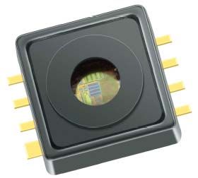
1.2 Package Description
Infineons PG-DSOF-8-16 package is a leaded SMD package where the leads are bent inside the molding
compound (Thermo set) with a lead surface finish of Ni/NiP/Pd/Au.
The PG-DSOF-8-16 package is supplied with a fixed lid, see Figure 1
Features:
• Green SMD package
• fulfills the conditions for lead-free board assembly
• optimized regarding mechanical stress influences
Figure 1 PG-PDSOF-8-16 with fixed lid
Application Note 7 Rev. 2.1, 2011-09-21PG-DSOF-8-16
Recommendations for Assembly
Package Handling
2 Package Handling
2.1 ESD Protective Measures
Semiconductor devices are normally Electrostatic Discharge Sensitive Devices (ESDS) requiring specific
precautionary measures regarding handling and processing. Discharging of electrostatically charged objects over
an IC, caused by human touch or processing tools may cause high current respectively high voltage pulses that
can damage or even destroy sensitive semiconductor structures. On the other hand, ICs may also be charged
during processing. If discharging takes place too quickly (hard discharge), it may cause load pulses and damages,
too. ESD protective measures must therefore prevent contact with charged parts as well as charging of the ICs.
Protective measures against ESD include handling, processing and packing of ESDS. A few hints are provided
below on handling and processing.
2.1.1 ESD Protective Measures in the Workplace
• Standard marking of ESD protected areas
• Access control with tester for footwear and wrist strap
• Air conditioning
• Dissipative and grounded floor
• Dissipative and grounded working and storage areas
• Dissipative chairs
• Earth (“ground”) bonding points for wrist straps
• Trolleys or carts with dissipative surfaces and wheels
• Suitable shipping and storage containers
• No sources of electrostatic fields
2.1.2 Equipment for personal
• Dissipative/conductive footwear or heal grounder
• Garments
• Wrist straps
• Gloves or finger coats which are ESD-proven
• Regular training of staff
2.1.3 Production Installation and Processing Tools
• Machine and toolparts made of dissipative or metallic materials
• No materials having thin insulating layers for sliding tracks
• All parts reliable connected to ground potential
• No potential difference between individual machine and tool parts
• No sources of electrostatic fields
Detailed information on ESD protective measures may be obtained from the ESD specialist through Area Sales
Offices. Our recommendations are based on the internally applicable standards IEC61340-5-1 and ANSI/ESD
S2020.
Application Note 8 Rev. 2.1, 2011-09-21PG-DSOF-8-16
Recommendations for Assembly
Package Handling
2.2 Packing of components
List of relevant standards which should be considered
Infineon packs according to the IEC 60286-* series (IEC 60286-3 is similar to the EIA 481-*).
IEC 60286-3 Packaging of components for automatic handling - Part 3:
Packaging of surface mount components on continuous tapes
IEC 60286-4 Packaging of components for automatic handling - Part 4:
Stick magazines for dual-in-line packages
IEC 60286-5 Packaging of components for automatic handling - Part 5:
Matrix trays
Moisture sensitive Surface Mount Devices are packed according to IPC/JEDEC J-STD-033*:
Handling, Packing, Shipping and Use of Moisture/Reflow Sensitive Surface Mount Devices
Other references:
ANSI/EIA-481-* EIA Standard
8 mm through 200 mm embossed Carrier Taping and
8 mm & 12 mm Punched Carrier Taping of Surface Mount Components for Automatic
Handling
PDSOF packages are supplied in tapes on reel for feeding in an automatic pick&place machine.
Detailed packing drawings: More information are available on www.infineon.com/package
Application Note 9 Rev. 2.1, 2011-09-21PG-DSOF-8-16
Recommendations for Assembly
Package Handling
2.3 Moisture Sensitive Components (MSL classification)
For moisture sensitive packages, it is necessary to control the moisture content of the components. Penetration
of moisture into the package molding compound is generally caused by expose to ambient air. In many cases,
moisture absorption leads to moisture concentrations in the component that are high enough to damage the
package during the reflow process. Thus it is necessary to dry moisture sensitive components, seal them in a
moisture-resistant bag, and only remove them immediately prior to board assembly. The permissible time (from
opening the moisture barrier bag until the final soldering process), which a component can remain outside the
moisture barrier bag, is a measure of the sensitivity of the component to ambient humidity (MSL). The most
commonly applied standard IPC/JEDEC J-STD-020C defines eight different MSLs, see Table 1.
The Moisture Sensitivity Level for PG-DSOF-8-16 is MSL1.
Table 1 Moisture Sensitivity Level
Level Floor Life Soak requirements
Time Conditions Time Conditions
1 Unlimited 30°C / 85% RH 168 hours 85°C / 85% RH
2 1 year 30°C / 60% RH 168 hours 85°C / 60% RH
2a 4 weeks 30°C / 60% RH 696 hours 30°C / 60% RH
3 168 hours 30°C / 60% RH 193 hours 30°C / 60% RH
4 72 hours 30°C / 60% RH 96 hours 30°C / 60% RH
5 48 hours 30°C / 60% RH 72 hours 30°C / 60% RH
5a 24 hours 30°C / 60% RH 48 hours 30°C / 60% RH
6 Time On Label (TOL) 30°C / 60% RH TOL 30°C / 60% RH
If moisture sensitive components have been exposed to ambient air for longer than the specified time according
to their MSL, or the humidity indicator card indicates to much moisture after opening a Moisture Barrier Bag (MBB),
the components have to be baked prior to the assembly process. Please refer to IPC/JEDEC J-STD-020C for
details [1]. Baking a package to often can cause solderability problems due to oxidation and/or intermetallic
growth. In addition, packing materials (tape and reel) may not withstand higher baking temperatures.
Application Note 10 Rev. 2.1, 2011-09-21PG-DSOF-8-16
Recommendations for Assembly
Package Handling
2.4 Storage and Transportation Conditions
Improper transportation and unsuitable storage of components can lead to a number of problems during
subsequent processing, such as poor solderability, delamination, and package cracks effects.
List of relevant standards which should be considered
IEC 60721-3-0 Classification of environmental conditions: Part3:
Classification of groups of environmental parameters and their severities; Introduction
IEC 60721-3-1 Classification of environmental conditions: Part3:
Classification of groups of environmental parameters and their severities; Storage
IEC 60721-3-2 Classification of environmental conditions: Part3:
Classification of groups of environmental parameters and their severities; Transportation
IEC 61760-2 Surface mounting technology - Part 2:
Transportation and Storage conditions of surface mounting devices (SMD) -
Application Guide
IEC 62258-3 Semiconductor Die Products - Part 3:
Recommendations for good practice in handling, packing and storage
ISO 14644-1 Clean rooms and associated controlled environments Part 1:
Classification of airborne particulates
Table 2 General Storage Conditions - Overview
Product Condition for Storing
Wafer/Die N2 or MBB1) (IEC 62258-3)
Component - moisture sensitive MBB (JEDEC J-STD-033*)
Component - not moisture sensitive 1K2 (IEC 60721-3-1)
1) MBB = Moisture Barrier Bag
Maximum Storage Time
The conditions to be complied with in order to ensure problem-free processing of active and passive components
are described in standard IEC 61760-2.
Internet links to Standards Institutes
American National Standards Institute (ANSI)
Electronics Industries Alliance (EIA)
Association Connecting Electronics Industries (IPC)
Application Note 11 Rev. 2.1, 2011-09-21PG-DSOF-8-16
Recommendations for Assembly
Package Handling
2.5 Handling Damage and Contamination
Automatic or manual handling of components in or out of the component packing may cause mechanical damage
to package leads and/or body
Generally the components in the packing are ready to use. The PG-DSOF-8-16 package is supplied with a fixed
plastic lid. The flat surface of this lid on top of the package allows handling with standard pick and place tools.
Care should be taken during handling to avoid damage to the gel and lid:
• the gel can be damaged due to access through the hole in the lid
• the lid can be damaged through bending with push/pull forces. Lid bending with pull forces >1N and push
forces >5N should be avoided.
Any contamination applied to the component or packing may cause or induce processes that may lead to device
damage. The most critical issues are:
• Solderability problems
• Corrosion
• Electrical shorts (due to conductive particles)
2.6 Component Solderability
The sufficiently thick and wettable metal surfaces (final plating) of the device pins ensure good solderability, even
after a long storage time.
Note that the cut edges of the pins should be ignored in any assessment of the solderability.
Suitable methods for the assessment of solderability can be derived from JESD22B 102 or IEC60068-2-58.
Application Note 12 Rev. 2.1, 2011-09-21PG-DSOF-8-16
Recommendations for Assembly
Assembly
3 Assembly
The PG-DSOF-8-16 package is qualified for Pb-free reflow soldering process.
3.1 Process flow for reflow soldering
Typical flow for mounting SMDs with reflow soldering process:
• Application of solder paste to the PCB
• Solder paste inspection
• Placement of component on PCB
• Inspection
• Reflow soldering
• Inspection
3.2 Solder Paste
Solder paste consists of solder alloy and a flux system. Normally the volume is split into about 50% alloy and 50%
flux and solvents. In term of mass, this means approximately 90 wt% alloy and 10 wt% flux system and solvents.
The flux system has to remove oxides and contaminants from the solder joints during soldering process. The
capability of removing oxides and contaminants depends on the activation level of the used flux.
The contained solvent adjusts the viscosity needed for the solder paste application process. The solvent has to
evaporate during reflow process.
3.3 Pick-and-Place
3.3.1 Component Placement
Although the self-alignment effect due to the surface tension of the liquid solder will support the formation of
reliable solder joints, the components have to be placed accurately according to the geometry. Positioning the
package manually is not recommended. For PG-DSOF-8-16 an automatic pick-and-place machine is
recommended to achieve reliable solder joints.
For PG-DSOF-8-16 package with a pad width of 0.4 mm (respectively 0.8 mm) and a pitch of 1.27 mm, an
automatic pick-and-place machine is recommended to achieve reliable solder joints.
Component placement accuracies of ±50 μm are obtained with modern automatic component placement
machines using vision systems. With these systems, both the PCB and the components are optically measured
and the components are placed on the PCB at their programmed positions. The fiducials on the PCB are located
either on the edge of the PCB for the entire PCB or additionally on individual mounting positions (local fiducials).
They are detected by a vision system. Recognition of the packages immediately before the mounting process is
performed by a special vision system, enabling the complete package to be correctly centered.
The PG-DSOF-8-16 device is delivered in tape and reel packing which is suitable for being used in pick-and-place
equipment.
Application Note 13 Rev. 2.1, 2011-09-21PG-DSOF-8-16
Recommendations for Assembly
Assembly
3.3.2 Nozzle
A pick-up nozzle suitable for the package body size should be used. Regarding the PG-DSOF package it is
recommended that the used nozzle seals on the package rim. If a smaller nozzle is used this may lead to increased
force in the package center, nozzle shape and size are more critical in this case.
For Pick and Place should be considered:
• a dynamic vacuum pressure puls of min. 10 kPa can be applied.
• the nozzle should be sealed on the package rim.
• if the nozzle is sealed on the lid, push/pull forces >5N should be avoided.
Recommendation for nozzle, sealed on the package rim:
Figure 2 Recommended pick-up nozzle for PG-DSOF package
3.4 Reflow Soldering
Reflow soldering is the most common technique to attach SMD components to a circuit board. The goal of the
reflow process is to melt the powder particles in the solder paste, thereby joining the appropriate surfaces, to
create a strong metallurgical bond after solidification of the solder.
During the reflow process, each solder joint has to be exposed to temperatures above the melting point of solder
for a sufficient time to get optimum solder joint quality, whereas overheating the PCB has to be avoided.
It is important that the maximum temperature of the package during reflow does not exceed the specified
peak temperature of the moisture level.
When using infrared (IR) ovens without convection, special care may be necessary to assure a sufficiently
homogeneous temperature profile for all solder joints on the PCB, especially on large, complex boards with
different thermal masses of the components. Using infrared soldering, the components are heated as a result of
absorbing IR radiation. Usually the heating is done with radiators positioned on either side in order to heat or
preheat the whole area surrounding of the solder joint, if possible. The temperature of the different components
may vary severely. Since the metallic terminals of the components exhibit only low absorption (because they
Application Note 14 Rev. 2.1, 2011-09-21PG-DSOF-8-16
Recommendations for Assembly
Assembly
reflect IR radiation), the heat has to be applied to the solder joints via the component itself, the heated PCB and
the ambient air.
Other ovens are based on heat transfer by infrared or vapor-phase.
Most reflow ovens use forced convection blowing hot air at different temperatures in different zones.
3.4.1 Forced Convection Reflow Process
The recommended reflow process is forced convection where the heat is transferred to the PCB in different zones
by heated air or nitrogen. The number of zones, volume of hot gas and oven design determine the capacity and
the ability to reproduce the optimum reflow profile, which is also influenced by:
• Board thickness and layout
• Differences in thermal mass of all components
• Maximum allowed component temperatures
A nitrogen atmosphere can generally improve solder joint quality, but is normally not necessary for soldering the
available package lead finishes. For the lead-free process with higher reflow temperatures, a nitrogen atmosphere
may reduce oxidation and improve solder joint quality.
3.4.2 Reflow Peak Temperature
Small volume SMD packages reach higher body temperature during reflow soldering to boards that have been
profiled for larger packages. Therefore, technical and/or business issues normally require thin, small volume SMD
packages to be classified at higher reflow temperatures, see IPC/JEDEC J-STD-020C. Table 3 shows the peak
reflow temperature for Pb-free soldering process related to the package thickness.
For PG-DSOF-8-16 package with a package thickness >2.5 mm and package volumePG-DSOF-8-16
Recommendations for Assembly
Assembly
3.4.4 PG-DSOF-8-16 Reflow Profile
Figure 3 shows the reflow profile classification acc. to IPC/JEDEC J-STD-020C for Pb-free assembly of SMD
packages.
300
tp
Tpeak
250
TL
Tsmax tL
200
temperature [°C]
Tsmin ts
150
100
50
0
0 100 200 300 400 500 600
time [sec]
Figure 3 Classification Reflow Profile
The PG-DSOF-8-16 package can be soldered using standard reflow processes and temperature profiles as per
IPC/JEDEC J-STD-020C, see Figure 3
Application Note 16 Rev. 2.1, 2011-09-21PG-DSOF-8-16
Recommendations for Assembly
Assembly
Figure 4 shows the recommended reflow profile and Table 4 the recommended reflow parameters for PG-DSOF-
8-16 with lid.
Figure 4 Recommended reflow temperature profile for PG-DSOF-8-16
Table 4 Reflow Profile Parameters
Profile Feature Value
TS min 150°C
TS max 200°C
Tpeak 250°C
TL 217°C
Average Ramp-up Rate (TS max to Tpeak) 3°C/sec max
Time ts (temperature from TS min to TS max) 60-180 sec min.
Time tL (temperature maintained above TL) 60 - 150 sec
Time tp (temperature maintained above Tpeak - 5°C) 20 - 40 sec
Ramp down rate 6°C/sec max.
Time 25°C to Tpeak 8 minutes max.
Application Note 17 Rev. 2.1, 2011-09-21PG-DSOF-8-16
Recommendations for Assembly
Assembly
3.5 Cleaning
After the soldering process, flux residues can be found around the solder joints. If a “no-clean” solder paste has
been used for printing, the flux residues usually do not have to be removed after the soldering process. However,
if the solder joints should be cleaned, the cleaning methods have to be selected by considering the package
requirements and environmental and safety aspects.
The PG-DSOF-8-16 package is compatible to standard PCB cleaning agents, for example VIGON™ A200 from
Zestron (www.zestron.com).
During the cleaning process, it should be ensured that there is no contamination inside the lid hole and no
mechanical damage to the gel (e.g. by applying a high pressure spray).
Application Note 18 Rev. 2.1, 2011-09-21PG-DSOF-8-16
Recommendations for Assembly
References
References
[1] IPC/JEDEC J-STD-020C (Moisture/Reflow Sensitivity Classification for Nonhermetic Solid State Surface
Mount Devices)
[2] JESD22-B102 (Test Method for Solderability)
[3] IEC 60068-2-58 (Test Methods for Solderability, resistance to dissolution of metallization and to soldering
heat of surface mounting devices)
Application Note 19 Rev. 2.1, 2011-09-21w w w . i n f i n e o n . c o m Published by Infineon Technologies AG
You can also read