Alternative Mazda Diagnostic Connection - Automotive Tech Info
←
→
Page content transcription
If your browser does not render page correctly, please read the page content below
July 2021

Alternative Mazda
Diagnostic Connection
Alternative Mazda Diagnostic Connection

With the Mazda platform, the most common scan             that wanted to be a Ford. If the Jag model used a Ford
equipment on the market would be the IDS, Snap-On,        network, you may have a scan tool with the ELM327.
MAC, Autel, Launch, etc.
                                                          Depending on the preference and what type of
Most, if not all, can read the entire network(s)          interface is being used, all have distinct benefits:
of the installed controllers and also include
                                                          (A) T
                                                               he ELM327 v1.4 or v1.5 is the most stable. The
bi-directional control(s).
                                                              “purchase” will need an internal update. It’s small
                                                              and portable. Those details will be in this article.
What about ELM327 devices - DIY
Years ago, these devices (or versions of them) came       (B) T
                                                               he OBDLink MX+ needs occasional updates and is
into the market as simplistic OBD II code readers that        just as portable.
connected to a PC three different ways:                   (C) T
                                                               he J2534-2 devices work as well and are very fast
    1. USB         2. Bluetooth           3. Wi-Fi            compared to the ELM devices. They are not the
                                                              “pocket size” but work well inside and outside the
All three personal versions are in use and we have            service bay.
been working with them over many years but prefer
the Bluetooth version. Bluetooth is far simpler.          What is the update?
                                                          The general purpose, well designed ELM327 device
Most Android and Apple devices connect in                 has communication lines that meet anything that is
the same fashion—USB needing adapters                     OBD II model compliant.
and software if required.
                                                          Ford and Mazda models use two networks:
OBD II has been talked about to death but there           High Speed CAN and Medium Speed CAN.
are some new, interesting applications that are
eye opening. Keeping it simple but understanding
the modes OBD II offers, is a reliable and simplistic
diagnostic approach.

Let’s change the rules
and dive into FORScan
This application comes in two flavors. One for the PC
(this one is on steroids) and another for the smart
phone or tablet version.

The PC version has the most options with bi-
directional control.

There are multiple flavors of ELM327 devices that “just
about everyone under the sun sells.” Many are not
very effective. There are however, very good OBD II
applications working with Android or a PC.
                                                           Figure 1: Tools used
Personal preferences that work
 • ELM327 v1.4b (BAFX versions are flawless)
 • OBDLink MX+ (STN1100 family with                       Tools Used
   firmware updates)                                      FORScan
 • J2534-2 CarDAQ Plus (WiFi) and Plus2 (USB)             CarDAQ Plus attached to WiFi
                                                          And or ELM327 - OBDLink MX+
Added is a 1 meter OBD extension cable (never lose        OBD extension cable
that OBD tool again).                                     90 amp floating power supply
                                                          Manometer with test cap
This application (FORScan) works on Ford and Mazda
models. Honorably mentioned are the Jag models            Camera, pen, paper and screen-capturing software

Import Service                                                                                       July 2021       2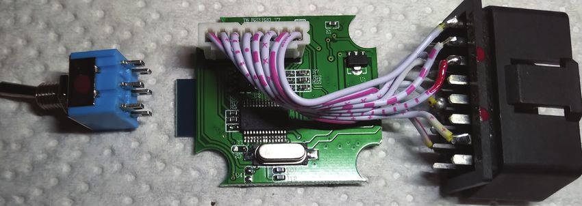
Alternative Mazda Diagnostic Connection

The simple update is a switch (Double Pole, Double            The paint mark on the pin 14 original wire of the DLC
Throw [DPDT]) that is easily installed into the               is to be de-soldered and will be soldered to the red
ELM327. FORScan requests a connection if the switch           side of the switch (center contact leg).
is installed that will access the networks and the
attached controllers.                                         The opposite pin 6 of the DLC will also be de-soldered
                                                              and soldered to the opposite side of the center
A non switching ELM device would have the illustrated         contact leg of the DPDT switch.
green and red wires connected to the High Speed
CAN High and CAN Low connections at Pins 6 and 14
on the DLC. This will be the standard connection for
                                                               Note 1
the ELM328 device.                                             Toggle the switch and the layout of the pins is
                                                               evident with the shop multimeter.
Using the diagram, Pins 6 and 14 are
removed from the DLC and connected
to the DPDT center terminals.

The updated ELM and DPDT switch will                                          1 2 3 4 5 6 7 8
connect Pins 3 and 11 (Medium Speed
CAN) or Pins 6 and 14 (High Speed CAN).
                                                                              9 10 11 12 13 14 15 16
NOTE
Not all ELM 327 pin layouts on the circuit
board are identical; use the hand made
Photoshop illustration and notes.

With care, razor off the label and place
it aside, remove the four screws and
open the shell.                              Figure 2: Ford DLC Connection       16    2    7    15    6    14   10     4/5

With the device opened and laying the        Red Pin 14 original connection		         Green Pin 6 original connection
DPDT switch in line with the ELM, some       Move connection to DPDT micro switch.
paint marks in red identified pin 14 and     Pin 1:                                     Pin 9:
the blank pin 11 of the DLC. The switch      Pin 2: J1850 BUS +                         Pin 10: J1850 BUS -
was also identified with a red dot.          Pin 3: CAN Hi Med Speed                    Pin 11: CAN Lo Med Speed
                                             Pin 4: Chassis Ground                      Pin 12:
An old computer ribbon was used to           Pin 5: Signal Ground                       Pin 13:
make up a harness and attach the             Pin 6: CAN Hi High Speed                   Pin 14: CAN Lo High Speed
extra CAN wires from the DPDT switch         Pin 7: ISO 9141-2 K Line                   Pin 15: ISO 9141-2 L Line
to the DLC.                                  Pin 8:                                     Pin 16: Battery 12V Fused

 Figure 3: Opened ELM

Import Service                                                                                             July 2021      3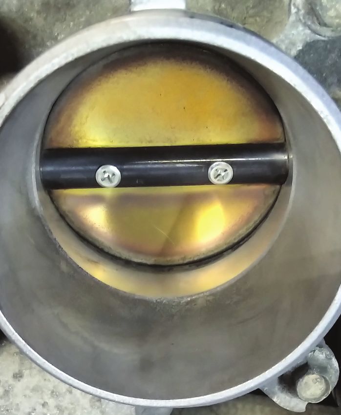
Alternative Mazda Diagnostic Connection
A switched network is now created.
Note 2
The added 1 meter DLC extension cable brings the Simply, the painted marks are a reference and directly
ELM or OBDLink to the operator for control or left fit the diagram.
on the dash. Reaching under the dash and fumbling
with a switch becomes a... distraction.
A few have been made for close associates, friends
Four wires of the ribbon cable must be manipulated. and acquaintances. With a high degree of care, all
At the red side, mark the CAN High pin 14 and solder have survived to this day.
it next to one leg at the end of the switch. With that
wire, solder it to DLC pin 14. On the opposite side of Some, but not all ELM devices, will fit the switch on
the switch, solder one wire to the switch for pin 6 and the end and, in some cases; the switch is mounted on
that opposite end to pin 6 of the DLC. the side. In either case, the cover of the ELM should be
identified as HI and LO relative to the switch position.
Circuit board Pins 6 and 14 are now reconnected to
the middle portion of the DPDT switch with Pins 6 and The HI position is the standard position when
14 of the DLC. diagnosing in OBD II mode.
Pin 11 of the DLC has a sacrificed wire soldered to The FORScan software can be downloaded here:
it. Paint it red. The opposite end is soldered to the forscan.org/download.html
opposite end of the switch on the red side.
It’s free to use all day long.
Pin 3 has the last wire soldered to the DLC and its
opposite end is soldered to the remaining pin of the Pick the flavor and again, the PC version has much
DPDT switch. more to it.
Read about the license and choose
the immediate needs.
Sign up at the FORScan web site to
access a license.
Without a license, no adaptations or
bi-directional controls are available.
What about the
2011 Mazda 3?
It just so happened, the facility had
a slight struggle with this model
Figure 4: Computer ribbon
and got dragged into the “mystery.”
Their first order of business was
Figure 5: to solve a MAF and misfire set of
Connected Switch faults. The MAF fault constantly
returned and the engine tended
to struggle up to idle speed and
seemed like a long crank condition.
Unfortunately, the primary faults
were never saved.
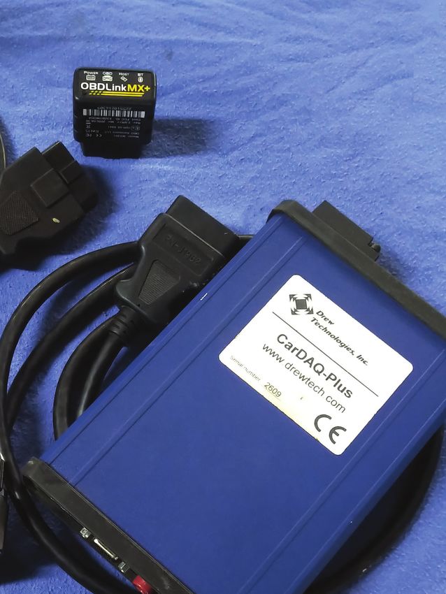
The setup: In this case, the J2534-2
was used.
Since this version is licensed, the
setup is by no means difficult for
Import Service July 2021 4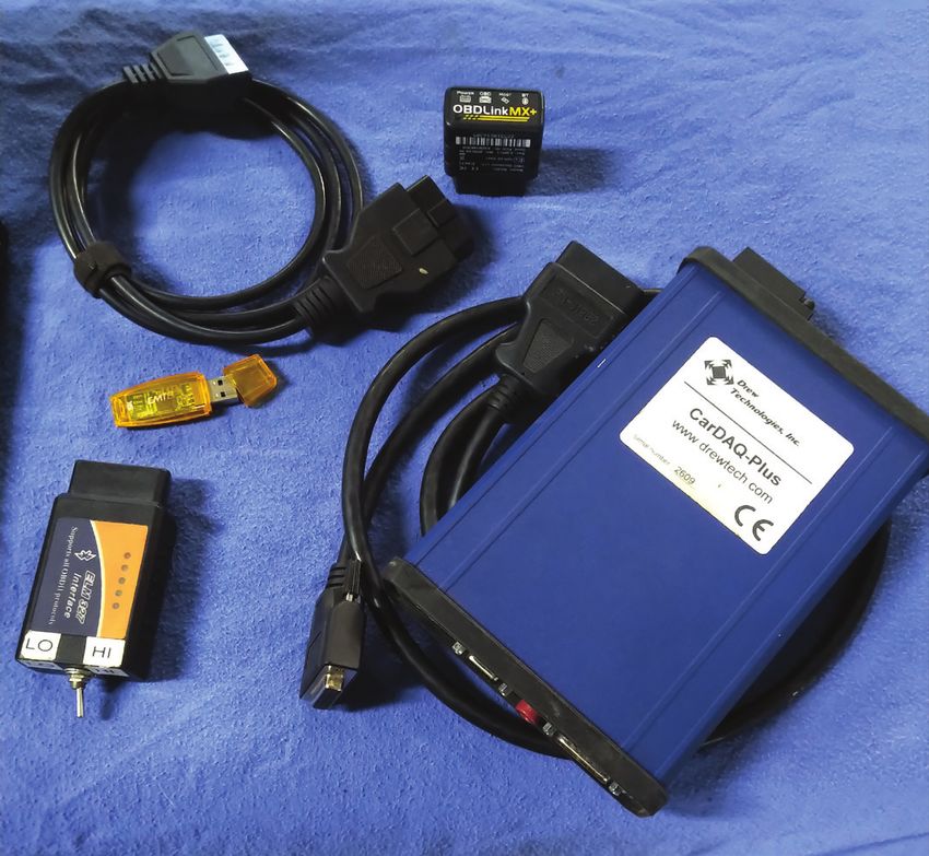
Alternative Mazda Diagnostic Connection

the ELM327 or OBDLink
MX+. Use the pairing code
that came with the device.

Codes can be: 1234
or 6789. Read the
documentation with
the device(s).

The J2534-2 can be a
direct USB connection
or in this case, a WiFi (ad
hoc) connection to the
laptop. If any or all devices    Figure 6: Shared with HS CAN
have been paired or set
up previously, they will
automatically connect.
                                          [13:52:08.340] Checking J2534 CarDAQ PLUS...

Remember to set the DPDT                  [13:52:08.966] Connection to adapter has been established: J2534 CarDAQ PLUS

switch to HI first.                       [13:52:08.967] Adapter: CarDAQ PLUS
                                          [13:52:09.068] Connection to vehicle has been established
If using a J2534-2                        [13:52:09.406] Vehicle: Mazda Axela/Mazda3 LF 2.0L 2011, VIN: JM1*******67689
device, there is one                      [13:54:08.334] Found MOdule: TCM - Transmission Control Module
task to complete.                         [13:54:11.661] Found module: PCM - Powertrain Control Module
                                          [13:54:18.156] DTCs in PCM: P0101:00-EC
That one option has to be
                                          [13:54:18.198] Found Module: OBDII - On Board Diagnostic II
set the first time. J2534-2
                                          [13:54:18.312] DTCs in OBDII: P0101-C
devices will communicate
with High Speed and                       [13:54:20.363] Found module: ABS - Antilock braking system
Medium Speed CAN                          [13:54:21.209] DTCs in ABS: U0428:62-60
networks because MS                       [13:54:23.088] Found module: BCM/GEM - Body Control Module/Generic Electronic Module
CAN support is shared                     [13:54:24.432] Found module: IC - Instrumetn Cluster
with HS CAN.                              [13:55:06.527] Found module: RCM - Restraint Control Module
                                          [13:55:07.639] Found module: EPS - Electronic-Controlled Power Steering
A J2534-1 device can not
                                          [13:55:09.867] Found module: ACU - Audio Control Unit
access the Medium
                                          [13:55:10.313] Found module: MID - Multi-Information Display
Speed Network.

FORScan will connect
                                 Figure 7: First Connection
to both networks and
access the name of the
controller(s) with the faults                                     The Module’s tab indicates both networks the J2534-2
associated to that controller.                                    device has access to. The ELM327 device will “ask and
                                                                  confirm” the network switch; follow the guide on the
The switched ELM device and the software will request             screen and activate the switch in the correct position.
the required switch position warnings on the screen.
                                                                  FORScan logs can be saved and found
The top line (Figure 7) indicates the device that                 in “My Documents\FORScan.”
accessed the Mazda with the recognized VIN and
software version.                                                 The software displays a well organized view of all
                                                                  faults by clicking them individually. Saving the logs
The top tabs access:                                              and numbering them will help towards a path and
Log – Configuration – Modules – Profiles                          final solution when those faults are corrected.

Import Service                                                                                                      July 2021    5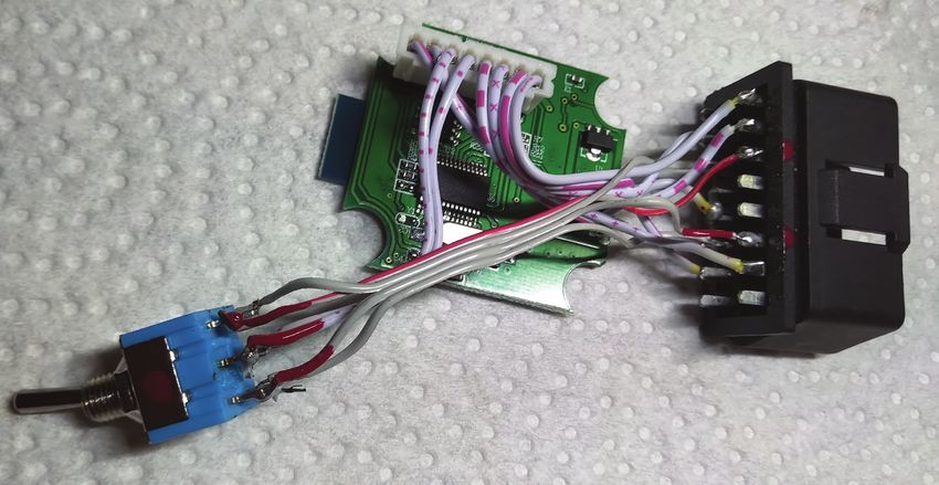
Alternative Mazda Diagnostic Connection

Clicking the OBD II at the left gives up the
generic fault:                                                - Mazda Axela/Mazda3 LF 2.0L
 • Code: P0101 - Mass or Volume Air Flow                         - HSCAN
   Sensor A Circuit Range/Performance                                    PCM - Powertrain Control Module
 • Status - Confirmed - malfunction                                      TCM - Transmission Control Module
   is confirmed                                                          OBDII - On Board Diagnostic II
 • Module: On Board Diagnostic II
                                                                         ABS - Antilock braking system
                                                                         BCM/GEM - Body Control Module / Generic Electronic Module
One more attention to add.                                               IC - Instrument Cluster
The vehicle owner or someone decided to
                                                                         RCM - Restraint Control Module
also replace the battery. Unfortunately it was
                                                                         EPS - Electronic-Controlled Power Steering
the incorrect size (dimensions) and the posts
were at the opposite side. It did fit but we
made sure the customer was aware of that                           - MSCAN
purchase and possible update.                                            ACU - Audio Control Unit
                                                                         MID - Multi-Information Display
The battery became the reason for the
next fault.
                                                       Figure 8: Network layout
U0428 - Invalid
Data Received From
Steering Angle                                        Code: P0101 - Mass or Volume Air Flow Sensor A Circuit Range/Performance
                              TCM       None
Sensor Module                                         Status:
                              PCM       P0101:00-EC
                                                      - DTC Maturing - Intermittent at Time of Request
Most notably -                OBDII     P0101-C       - Malfunction Indicator Lamp is On for this DTC
                                                      - Test not complete
Test not complete             ABS       U0428:62-60
                              BCM/...   None          Module: Powertrain Control Module
The suspicion                 IC`       None           Freeze Frame:
was either a                  RCM       None
                                                      -DTC: --- - DTC That Caused REquired Snapshot Data Storage
dead battery or                                       -FUELSYS: Closed Loop - Fuel System Status (Open/Closed Loop)
                              EPS       None          -LOAD: 26.27% - Calculated Load Value
jump starting it.                                     -ECT: 33°C - Engine collant temperature
Disconnecting the             ACU       None          -SHRTFT1: -10.94% - Short term fuel trim 1
battery may have              MID       None          LONGFT1: -2.34% - Long term fuel trim 1
                                                      -MAP: 29.0 kPa - Manifold absolute pressure sensor
also lost the ABS                                     -RPM: 1943 1/min - Engine Revolutions Per Minute
Steering Angle                                        -VSS: 0.0 km/h - Vehicle Speed
Sensor calibration.                                   -SPARKADV: 30.50° - Spark Advance
                                                      -IAT: 19°C - Intake Air Temperature
                                                      -MAF: 7.57 g/s - Mass Air Flow
The day before, the                                   -TP: 18.82% - Throttle Position
                                                      -RUNTM: 18s - Time Since Engine Start
facility replaced                                     -EGR_PCT: 0.00% - Commanded EGR
spark plugs and                                       -EVAP_PCT: 0.00% - Commanded Evaporative Purge
ordered a MAF                                         -FLI: 34.51% - Fuel Level
                                                      -WARM_UPS: 0 - Number Of Warm-ups Since DTCs Cleared
sensor for the                                        -CLR_DIST: 0.0 km - Distance since diagnostic trouble codes cleared
following day. The                                    -FTP: 0.0 kPa - Fuel Tank Pressure Transducer
repeating fault                                       -BARO: 100.0 kPa - Barometric pressure
                                                      -CATEMP11: 461°C - Catalyst Temperature Bank 1, Sensor 1
may have been the                                     -VPWR: 14.14 V - Control Module Voltage
reasoning for the                                     -LOAD_ABS: 20.00% - Absolute Load Value
shop to order a                                       -EQRAT11_CMD: 14.520 :1 - Commanded Equivalence Ratio (Air to Fuel Mixture) Bank 1
                                                      -TP_REL: 9.02% - Relative Throttle Position
MAF sensor. Let’s                                     -AAT: 19°C - Ambient Air Temperature
see what live data                                    -TP_B: 18.82% - Throttle Position Sensor 2
                                                      -APP_D: 11.76% - Accelerator Pedal Position D
the PCM displays.                                     -APP_E: 12.16% - Accelerator Pedal Position E
                                                      -TAC_PCT: 10.59% - Commanded Throttle Actuator Control
                                                      -ECT2_SUP: Yes - Engine Coolant Temperature Sensor 1 supported
Access the PCM                                        -ECT1_SUP: Yes - Engine Coolant Temperature Sensor 1 supported
To access live data
for any controller,
use the icon that       Figure 9: Freeze frame

Import Service                                                                                                          July 2021          6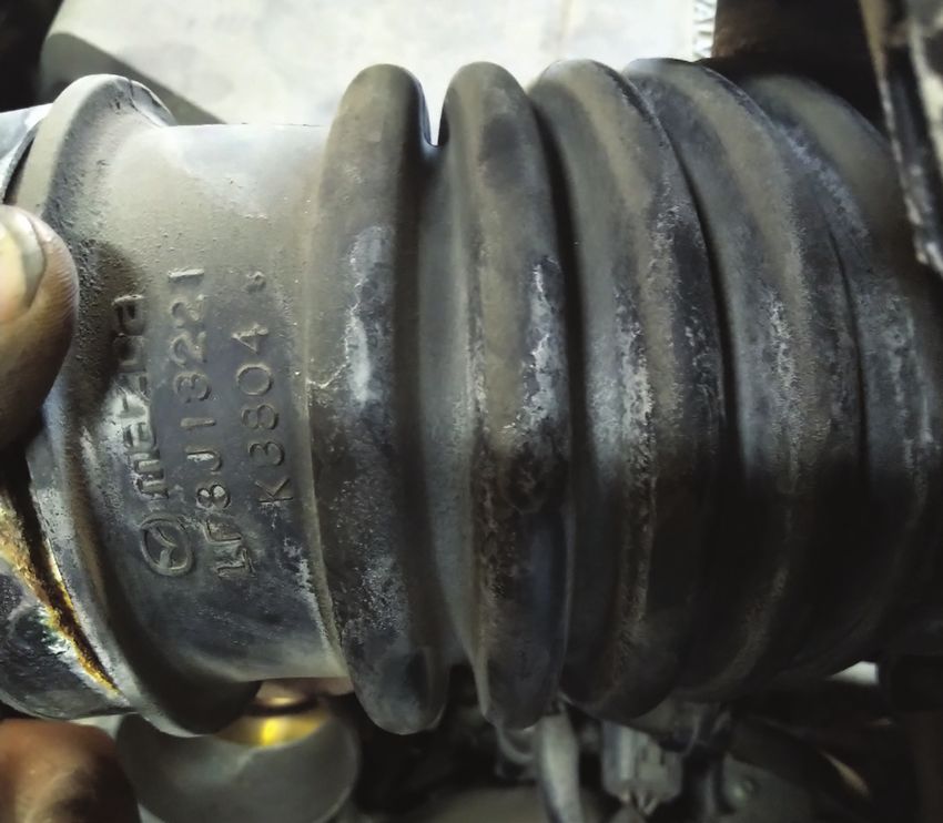
Alternative Mazda Diagnostic Connection

resembles a sine wave.
The next window will                      TCM       None
                                                                   Code: U0428 - Invalid Data received From Steering Angle Sensor Module
open the next choice
                                          PCM       P0101:00-EC
to click the PCM.                                                  Additional Fault Symptom:
                                          OBDII     P0101-C        -Signal Compared Failure
                                          ABS       U0428:62-60
Another window follows                                             Status:
                                          BCM/...   None
with all the PIDs the scan                                         -Malfunction Indicator Lamp is Off for this DTC
                                          IC`       None           -Test not complete
tool has access to.
                                          RCM       None
                                                                   Module: Antilock braking system
                                          EPS       None
The best and quickest
                                          ACU       None
method is to scroll the page,
use the Ctrl and Enter key                MID       None
combinations to choose
(highlight) the set of PIDs.
Once the selections are            Figure 10: ABS Fault
made, click or touch the
right arrow to send the
selection to the right screen.
                                    Module:       PCM           Type:    Read               Filter:

Using the up or down                 Name                  Description                                                 Selected PIDs:
arrows can arrange the                                                                                                 AAT (°C)
                                     AAT                Ambient Air Temperature
data in any order.                   ACCS               Air Conditioning compressor cycling switch                     ALTF (%)
                                     AC_REQ             A/C Request Signal                                             ALTT V (V)
If the choices are correct           AFR                Air fuel reatio                                                ARPMDES (1/min)
                                     AFR_ACT            Actual AFR
and needed PIDs set is a live                                                                                          ECT (°C)
                                     ALTF               Generator field current control duty signal
test, click the check mark at        ALTT V             generator output voltage                                       MAF (g/s)
the bottom of the window.            APP                Accelerator Pedal Position                                     MAF(V (V)
                                     APP1               Accelerator pedal position sensor 1                            MAP (kPa)
                                     APP2               Accelerator pedal position sensor 2
The image “Data Screen”                                                                                                MAP_V (V)
                                     APP_D              Accelerator Pedal Position D
(next page) has a                    APP_E              Accelerator Pedal Position E
Play icon. Click it and the          ARPMDES            Desired RPM
screen will populate                 BARO               Barometric pressure
with the PID choices.                BARO               Barometric pressure
                                     BOO                Brake ON/OFF
                                     BPA                Brake Pressure Applied switch
Be aware with any scan               CATEMP11           Catalyst Temperature Bank 1, Sensor 1
tool. All selected PIDs              CHRGLP             Generator Warning Light
are subjected to:                    CLR_DIST           Distance since diagnostic trouble codes cleared
(a) Request      (b) Read          Figure 11: Data Configuration
(c) Write        (d) Display

All this takes place one PID at a time, dependent on PC
and scan tool processing speed.
                                                                                  AAT, °C             ARPMDES, 1/min       MAF_V, V

                                                                                    23                   1191               1.47
And the process begins again at the first PID.
                                                                                  ALTF, %                 ECT, °C          MAP, kPa

The top of the screen has three tabs. The image                                   32.15                    41               30.0
named “Data Screen” (next page) is associated with                               ALTTV, V                MAF, g/s          MAP_V, V
the Dashboard Tab. This screen indicates a cold start.
                                                                                 14.88                    4.12              1.22
The image “Oscilloscope” (next page) begins to look
more like other related software.

The next tab is Table. This is likely going to appear
quicker in refresh rate and similar to the primary
Dashboard. The MAF values appeared normal.                          Figure 12: Data screen

Import Service                                                                                                           July 2021         7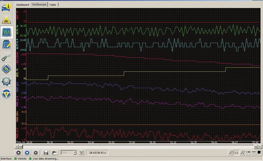
Alternative Mazda Diagnostic Connection
Figure 13: Oscilloscope
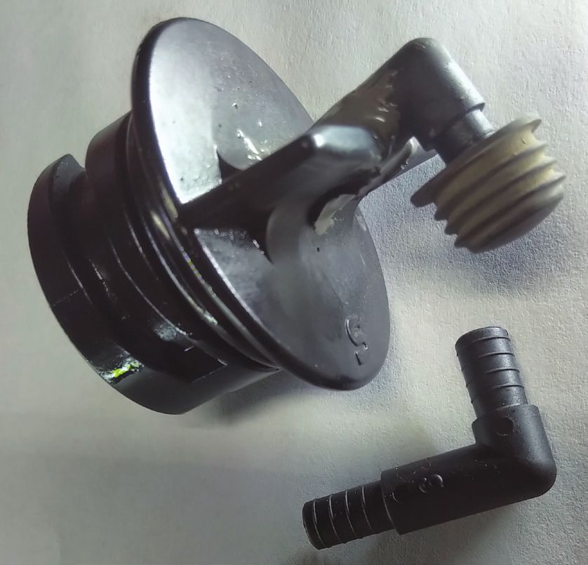
Figure 15: PCV test
Name Value Description
AAT 21°C Ambient Air Temperature
ALTF 36.55% Generator Field Current Control Duty Signal
ALTT V 14.50 V generator output voltage
ARPMDES 970 1/min Desired RPM
ECT 53°C Engine coolant temperature
MAF 3.04 g/s Mass Air Flow
MAF_V 1.33 V Mass Air Flow
MAP 29.0 kPa Manifold absolute pressure sensor
MAP_V 1.15 V Manifold absolute pressure sensor
Figure 16: Test Cap
Figure 14: Table
The Dashboard, Oscilloscope and Table tabs do work Instructions: Attach one end only from the test cap to
quickly together but great to monitor, especially with the manometer. The other end of the manometer is
Screen Recording software for playback. open to atmosphere. Cap the tool when finished with
the test.
Starting the engine was interesting – Long crank –
Repeating MAF Fault.
Test 2
Disconnecting and stretching the air tube connecting
With the Dashboard or Table view, the data for the
to the throttle body reveals no tears and contains a
MAF looked reasonable but two more tests were
attempted, just to make sure. new air filter. (See Figure 17, next page.)
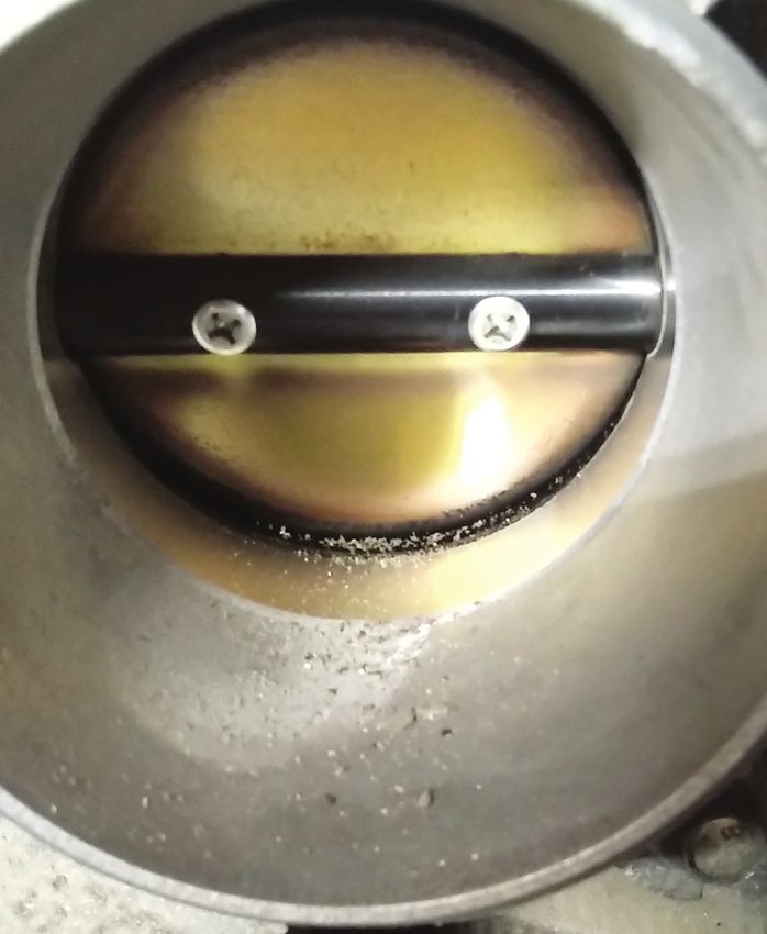
A deeper inspection revealed the reason for the long
Test 1
Two images side by side: The left image has the crank and MAF repeating faults. The throttle body was
dipstick inserted in place and the right image has the sticking from all the oil and debris stuck to the back
dipstick removed. This is a valid test with no apparent side of the throttle blade. With a light, there appears
PCV leaks. This test cap is a DIY from an aftermarket to be more oil than normal puddling within the
store and a battery vent tube glued into place. bottom floor of the intake manifold. This Mazda was
Consider this test as normal. due for an oil change within a month.
Import Service July 2021 8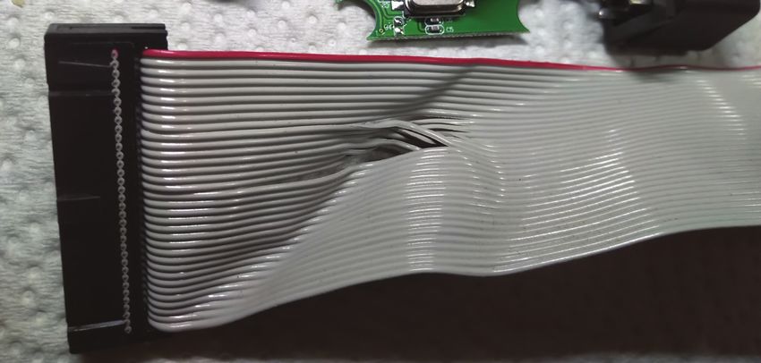
Alternative Mazda Diagnostic Connection

Figure 17: Air Tube

Did the shop installing the MAF sensor address the
starting problem? NO!

What the cleaning did accomplish was the immediate
starting rpm increase and much faster startup. The
starting rpm increase and drop to normal rpm was           Figure 18: Dirty Throttle Body
noticeable with the MAF fault not returning.

If the fault was evident, the MAF fault would have
been recorded immediately without cleaning the
throttle body.

The PCM had an expectation of a MAF value during
cranking and startup. A contaminated throttle body
decreased airflow during the cranking and eventual
startup. A thorough brush and chemical cleaning was
the solution.

What about the ABS fault with
the Steering Angle Sensor?
The Steering Angle Sensor fault returned with every
key cycle.

This is where FORScan accomplished and immediately
reset the fault.

With a power supply attached, click the Wrench icon
and choose the ABS control module. Click on the
module reset option and wait until the time has expired.
Heed all of the software warnings with any reset.

When looking at the layout and functions of this
software, it is a reminder of other scan tool functions
available on the market.                                   Figure 19: Clean Throttle Body

Import Service                                                                              July 2021   9
Alternative Mazda Diagnostic Connection

                                                                    Action needed!
       [14:27:56.571] Module Reset has been started
       [14:28:11.042] Please wait... 10 seconds                                   Please turn the ignition ON,
                                                                                  but don’t start the engine.

                                                                                    Ok                     Cancel

                                                                 Figure 21: Warning

                                                                                               Successful DTC reading,
                                                                       TCM        None
                                                                                               no error codes found
                                                                       PCM        None
                                                                                               Module: Transmission
                                                                       OBDII      None
                                                                                               Control Module
Figure 20: Module Reset                                                ABS        None
                                                                       BCM/...    None
With this model, the inclination was to leave the
                                                                       IC`        None
driver’s window open and reach into the passenger
                                                                       RCM        None
compartment to cycle the ignition key. During this test,
there was no intervention, no one sat in the vehicle,                  EPS        None

the steering was not moved (dead ahead position),                      ACU        None
doors not opened and no brakes were applied.                           MID        None

After the completion of the reset, no faults returned.
A quick road test also confirmed that no faults were             Figure 22: Clear Scan
recorded and the ABS functioned properly.                        ABS monitor the “G” yaw-rate force, longitudinal and
                                                                 acceleration sensors, including the Steering Angle Sensor.
Side note: Another quick test is to perform figure 8’s
safely in a large parking area at slow speeds with one           FORScan can monitor the installed sensors, and
straight ahead stop without applying the ABS. This is            the graphing feature is an advantage with a second
dependent on the model.                                          technician or by capturing a screen recording.

Another test with models that have stability control             This how the Mazda 3 was repaired and keeping
is to be a little rough on the vehicle and to have the           it simple. |

                                                      Publisher: Tamra Ayers Banz
                                                                                                    CAUTION: VEHICLE SERVICING PERFORMED
                                                      Editorial Director: Dick Moritz               BY UNTRAINED PERSONS COULD RESULT
                                                                                                    IN SERIOUS INJURY TO THOSE PERSONS
                                                      Technical Writers:                            OR OTHERS. INFORMATION CONTAINED IN
                                                      Mike Bavaro, Peter Caro,                      THIS NEWSLETTER IS INTENDED FOR USE
                                                      Agostino (Augie) Ferron, Tim Pott,            BY TRAINED, PROFESSIONAL AUTO REPAIR
                                                      Gary Smith, Frank Walker                      TECHNICIANS ONLY. THIS INFORMATION IS
                                                                                                    PROVIDED TO INFORM THESE TECHNICIANS
          Import Service is a                         Group Publisher:                              OF CONDITIONS WHICH MAY OCCUR
          publication of Automotive                                                                 IN SOME VEHICLES OR TO PROVIDE
                                                      Christopher M. Ayers, Jr.                     INFORMATION WHICH COULD ASSIST THEM
          Tech Info, LLC. No part                                                                   IN PROPER SERVICING OF THESE VEHICLES.
          of this newsletter may be                   Creative Director:                            PROPERLY TRAINED TECHNICIANS HAVE THE
          reproduced without the                      Christopher M. Ayers III                      EQUIPMENT, TOOLS, SAFETY INSTRUCTIONS,
          express written permission                                                                AND KNOW-HOW TO PERFORM REPAIRS
                                                      Circulation Manager: Joann Turner             CORRECTLY AND SAFELY. IF A CONDITION IS
          of Automotive Tech Info.
                                                                                                    DESCRIBED, DO NOT ASSUME THAT A TOPIC
                                                      Import Service®                               COVERED IN THESE PAGES AUTOMATICALLY
                                                      134B River Rd., Montague, NJ 07827            APPLIES TO YOUR VEHICLE OR THAT YOUR
                                                      importservicemag.com                          VEHICLE HAS THAT CONDITION.
                                                      Contact@AutomotiveTechInfo.com

Import Service                                                                                                          July 2021             10
You can also read