Simple wave-field rendering for photorealistic reconstruction in polygonbased high-definition computer holography
←
→
Page content transcription
If your browser does not render page correctly, please read the page content below
Simple wave-field rendering for
                 photorealistic reconstruction in polygon-
                 based high-definition computer
                 holography

                 Kyoji Matsushima
                 Hirohito Nishi
                 Sumio Nakahara

Downloaded From: https://www.spiedigitallibrary.org/journals/Journal-of-Electronic-Imaging on 04 Jul 2021
Terms of Use: https://www.spiedigitallibrary.org/terms-of-use
Journal of Electronic Imaging 21(2), 023002 (Apr–Jun 2012)

                Simple wave-field rendering for photorealistic reconstruction
                  in polygon-based high-definition computer holography
                                                                              Kyoji Matsushima
                                                                                Hirohito Nishi
                                                                               Kansai University
                                                               Department of Electrical and Electronic Engineering
                                                                3-3-35 Yamate-cho, Suita, Osaka 564-8680, Japan
                                                                         E-mail: matsu@kansai-u.ac.jp

                                                                               Sumio Nakahara
                                                                               Kansai University
                                                                     Department of Mechanical Engineering
                                                                3-3-35 Yamate-cho, Suita, Osaka 564-8680, Japan

                                                                                                     can exceed 4 billion pixels, optically reconstruct true spatial
                Abstract. A simple and practical technique is presented for creating
                fine three-dimensional (3D) images with polygon-based computer-                      images that give continuous motion parallax both in horizon-
                generated holograms. The polygon-based method is a technique                         tal and vertical directions without any additional equipment
                for computing the optical wave-field of virtual 3D scenes given by                   such as polarizing eyeglasses. The reconstructed spatial
                a numerical model. The presented method takes less computation                       images provide almost all depth cues such as dispersion,
                time than common point-source methods and produces fine spatial                      accommodation, occlusion, and convergence. Thus, the
                3D images of deep 3D scenes that convey a strong sensation of
                depth, unlike conventional 3D systems providing only binocular dis-
                                                                                                     computer holograms give viewers a strong sensation of
                parity. However, smooth surfaces cannot be reconstructed using the                   depth that has not been possible for conventional 3D systems
                presented method because the surfaces are approximated by planar                     providing only binocular disparity. Unfortunately, these
                polygons. This problem is resolved by introducing a simple rendering                 computer holograms cannot be reconstructed by current
                technique that is almost the same as that in common computer gra-                    video devices such as liquid crystal displays because of
                phics, since the polygon-based method has similarity to rendering                    their extremely high definition. However, the high-definition
                techniques in computer graphics. Two actual computer holograms
                are presented to verify and demonstrate the proposed technique.
                                                                                                     holograms presage the great future of holographic 3D
                One is a hologram of a live face whose shape is measured using                       displays beyond Super Hi-Vision.
                a 3D laser scanner that outputs polygon-mesh data. The other is                          The synthetic fringe of a high-definition computer holo-
                for a scene including the moon. Both are created employing the                       gram is computed using a new algorithm referred to as the
                proposed rendering techniques of the texture mapping of real photo-                  polygon-based method7 instead of using conventional point-
                graphs and smooth shading. © 2012 SPIE and IS&T. [DOI: 10.1117/1
                                                                                                     based methods.8,9 In point-based methods, object surfaces
                .JEI.21.2.023002]
                                                                                                     are regarded as being covered with many point sources of
                                                                                                     light, whereas object surfaces are approximated by planar
                                                                                                     polygons regarded as surface sources of light in the poly-
                1 Introduction                                                                       gon-based method. The point-based methods are simple
                In classical holography, the object wave of a real object is                         but commonly time-consuming. It is almost impossible to
                recorded on light-sensitive films employing optical interfer-                        create full-parallax high-definition computer holograms
                ence with a reference wave. The object wave is optically                             of occluded 3D scenes using point-based methods, even
                reconstructed through diffraction by the fringe pattern.                             though many techniques have been proposed to accelerate
                Therefore, real existing objects are required to create a three-                     computation.10–15. The polygon-based method remarkably
                dimensional (3D) image in classical holography. For a long                           speeds up the computation of the synthetic fringe because
                time, it was not possible to create fine synthetic holograms                         far fewer polygons than point sources are needed to form
                for virtual 3D scenes such as those in modern computer                               a surface. Thus, some variations of the polygon-based
                graphics (CG).                                                                       method have been proposed for computing the fringe pattern
                   Recently, the development of computer technologies and                            even more quickly.16,17 In polygon-based computer hologra-
                new algorithms have made it possible to create brilliant syn-                        phy, the silhouette method is also used for light-shielding
                thetic holograms.1–6 These holograms, whose dimensions                               behind an object.1,18,19
                                                                                                         A disadvantage of the polygon-based method is that
                                                                                                     techniques have not been established for photorealistic
                Paper 11282 received Sep. 30, 2011; revised manuscript received Mar. 6,              reconstruction in high-definition holography. Some early
                2012; accepted for publication Mar. 12, 2012; published online Apr. 26,
                2012.
                                                                                                     high-definition holograms were created employing a basic
                                                                                                     diffuser model that simply corresponds to the flat shading
                0091-3286/2012/$25.00 © 2012 SPIE and IS&T                                           of CG. As a result, the reconstructed surface is not a smooth

                Journal of Electronic Imaging                                               023002-1                                         Apr–Jun 2012/Vol. 21(2)

Downloaded From: https://www.spiedigitallibrary.org/journals/Journal-of-Electronic-Imaging on 04 Jul 2021
Terms of Use: https://www.spiedigitallibrary.org/terms-of-use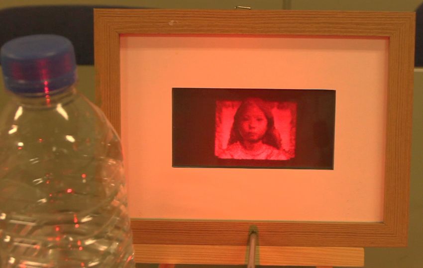
Matsushima, Nishi, and Nakahara: Simple wave-field rendering : : :

                curved surface but an angular faceted surface, and the                               computation time is proportional to the product of the
                borders of polygons are clearly perceived in the reconstruc-                         number of point sources and the number of pixels in the
                tion. This problem is peculiar to polygon-based methods. In                          hologram. Since this product is gigantic number for high-
                the early development of CG, the rendering of polygon-mesh                           definition holograms, the computation commonly takes
                objects suffered the same problem, but they have been                                a ridiculously long time. The polygon-based method is
                resolved with simple techniques.                                                     illustrated in Fig. 1(b). Object surfaces are composed of
                    Photorealistic reconstruction of computer holograms has                          many polygons in this method. Each polygon is regarded
                been discussed using a generic theoretical model in the lit-                         as a surface source of light whose shape is polygonal.
                erature.20 However, although the discussion is based on a                            Wave-fields emitted from the slanted polygons are computed
                generic model, fringe patterns are eventually computed                               by numerical methods based on wave optics. Even though
                with the point-based method. In addition, the surface patches                        the individual computation time for a polygon is longer than
                used in the study are assumed to be parallel to the hologram.                        that for a point source, the total computation time using the
                Thus, it is difficult to apply this model to our polygon-based                       polygon-based method is remarkably shorter than that using
                holograms in that the objects are composed of slanted                                point-based methods, because far fewer polygons than point
                patches. In this paper, we present a simple technique for the                        sources are required to form a surface.
                photorealistic reconstruction of a diffuse surface in high-
                definition computer holography. The technique makes use of                           2.1 Theoretical Model of Surface Sources of Light
                the similarity of the polygon-based method to conventional
                CG. The similarity means that the proposed technique is sim-                         We can see real objects illuminated by a light source because
                ple, fast and practical. Here, we use the term “rendering” to                        the object surfaces scatter the light, as shown in Fig. 2(a). If
                express computation of the fringe pattern and creation of 3D                         we suppose that the surface is composed of polygons and we
                images by computer holograms because of the similarity to                            focus on one of the polygons, the polygon can be regarded as
                CG. Since the polygon-based method is also a wave-oriented                           a planar distribution of optical intensity in 3D space. This
                method unlike the point-based method, the rendering tech-                            distribution of light is similar to that in a slanted aperture
                nique is referred to as “wave-field rendering” in this paper.                        irradiated by a plane wave, as in (b). The aperture has the
                    Two actual high-definition holograms are created to ver-                         same shape and slant as the polygon. However, a simple
                ify the techniques proposed in this paper. One is a 3D por-                          polygonal aperture may not behave as if it is a surface source
                trait; i.e., a hologram that reconstructs the live face of a girl.                   of light, because the aperture size is usually too large to dif-
                The polygon-mesh of the live face is measured using a 3D                             fract the incident light. As a result, the light passing through
                laser scanner. A photograph of the face is texture-mapped on                         the aperture does not sufficiently diffuse and spread over the
                the polygon-mesh with smooth shading. The other is for a                             whole viewing zone of the hologram. Obviously, the poly-
                scene of the moon floating in a starry sky. A real astropho-                         gonal surface source should be imitated by a diffuser
                tograph of the moon is mapped onto a polygon-mesh sphere.                            mounted in the aperture and having shape and tilt angle cor-
                Both holograms comprise more than 8 billion pixels and give                          responding to the polygon. Figure 2(b) shows the theoretical
                a viewing angle of more than 45° in the horizontal and 36° in                        model of a surface source of light for wave-field rendering.
                the vertical, and thus reconstruct almost all depth cues. As a
                result, these holograms can reconstruct fine true spatial 3D                         2.2 Surface Function
                images that give a strong sensation of depth to viewers.                             To compute the wave-field diffracted by the diffuser with
                                                                                                     polygonal shape, a surface function is defined for each indi-
                2 Summary of the Principle of the Polygon-Based                                      vidual polygon in a local coordinate system that is also spe-
                   Method                                                                            cific to the individual polygon. An example of the surface
                The polygon-based method is briefly summarized for conve-                            function is shown in Fig. 3, where the surface function of
                nience of explanation in this section. In the point-based                            polygon 2 of a cubic object in (a) is shown in (b). The surface
                method, spherical waves emitted from point sources are                               function hn ðxn ; yn Þ for polygon n is generally given in the
                computed and superposed in the hologram plane, as illu-                              form
                strated in Fig. 1(a). Considerably high surface density
                of the point sources, such as 103 ∼ 104 points∕mm2 , is                                          hn ðxn ; yn Þ ¼ an ðxn ; yn Þ exp½iϕðxn ; yn Þ;      (1)
                required to create a smooth surface with this method. The
                                                                                                     where an ðxn ; yn Þ and ϕðxn ; yn Þ are the real-valued amplitude
                                                                                                     and phase distribution defined in local coordinates ðxn ; yn ; 0Þ.
                                                                                                     The phase pattern ϕðxn ; yn Þ is not visible in principle,
                                                                                                     because all image sensors including the human retina can
                                                                                                     detect only the intensity of light, whereas the amplitude pat-
                                                                                                     tern an ðxn ; yn Þ directly determines the appearance of the
                                                                                                     polygon. Therefore, the diffuser should be applied using
                                                                                                     the phase pattern, while the shape of the polygon should
                                                                                                     be provided by the amplitude pattern.
                                                                                                        Since this paper discusses the rendering of diffuse sur-
                                                                                                     faces, the phase pattern used for rendering should have a
                                                                                                     wideband spectrum. In this case, a given single phase pattern
                                                                                                     can be used for all polygons. Note that if a specular surface is
                Fig. 1 Schematic comparison of the point-based method (a) and                        rendered, the spectral bandwidth should be restricted to limit
                polygon-based method (b).                                                            the direction of reflection. Furthermore, the center of the

                Journal of Electronic Imaging                                               023002-2                                                Apr–Jun 2012/Vol. 21(2)

Downloaded From: https://www.spiedigitallibrary.org/journals/Journal-of-Electronic-Imaging on 04 Jul 2021
Terms of Use: https://www.spiedigitallibrary.org/terms-of-use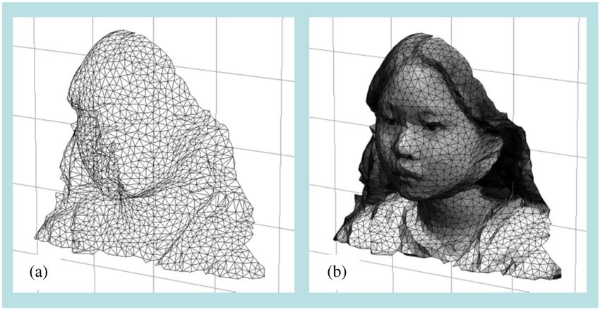
Matsushima, Nishi, and Nakahara: Simple wave-field rendering : : :

                                     Fig. 2 Theoretical model of polygonal surface sources of light (b) that imitate the surface of an object (a).

                Fig. 3 An example of surface functions (b) for polygon 2 of a cubic object (a). The amplitude image of the polygon field (c) after rotational transform
                agrees with the shape of the original polygon.

                spectrum should be shifted depending on the direction of the                         diffraction. Therefore, the rotational transform of light23,24
                polygon.5,21,22                                                                      is employed to calculate the polygon field in a plane parallel
                                                                                                     to the hologram. The resultant wave-field is shown in
                2.3 Computation of Polygon Fields                                                    Fig. 3(c). The polygon field after the rotational transform
                                                                                                     is then propagated over a short distance employing the
                The numerical procedure for computing polygon fields is                              angular spectrum method25 (AS) or band-limited angular
                shown in Fig. 4. The surface function of a polygon yielded
                                                                                                     spectrum method26 (BL-AS) to gather and integrate all poly-
                from vertex data of the polygon can be regarded as the dis-
                                                                                                     gon fields composing the object in a given single plane. This
                tribution of complex amplitudes; i.e., the wave-field of the
                                                                                                     plane is called the object plane. Here, note that the object
                surface source of light. However, the surface function is
                                                                                                     plane is not the hologram plane. The object plane should
                usually given in a plane not parallel to the hologram. This
                means that the polygon field cannot be computed in the                               not be placed far from the object, because polygon fields
                hologram plane using conventional techniques for field                               spread more in a farther plane, and thus, the computation
                                                                                                     takes longer. Therefore, the best solution is most likely to
                                                                                                     place the object plane so that the plane crosses the object.1
                                          Polygon mesh of object                                         The polygon fields gathered in the object plane propagate
                                                                                                     to the hologram or the next object plane closer to the holo-
                                      Field synthesis for each polygon                               gram to shield the light behind the object using the silhouette
                                                                                                     method.18,19 However, the frame buffer for the whole field in
                                       Generation of surface function
                                                                                                     the object plane is commonly too large to be simultaneously
                                                                                                     stored in the memory of a computer. Therefore, the field is
                                           Rotational transform                                      segmented and propagated segment by segment, using off-
                                            of surface function
                                                                                                     axis numerical propagation such as the shifted Fresnel
                                        Propagation of polygon field                                 method1,27 (Shift-FR) or shifted angular spectrum method2,28
                                             by AS or BL-AS                                          (Shift-AS).

                                          Addition of polygon field
                                              to frame buffer                                        3 Wave-Field Rendering for the Smooth Shading
                                                                                                       and Texture-Mapping of Diffuse Surfaces
                                      Propagation of whole object field
                                          by Shift-FR or Shift-AS                                    3.1 Basic Formulation
                                                                                                     In the polygon-based method, polygon fields are emitted
                                                Object field                                         toward the hologram along the optical axis. The brightness
                                                                                                     of the surface observed by viewers is estimated by radio-
                    Fig. 4 Numerical procedure for computing entire object fields.                   metric analysis7:

                Journal of Electronic Imaging                                               023002-3                                         Apr–Jun 2012/Vol. 21(2)

Downloaded From: https://www.spiedigitallibrary.org/journals/Journal-of-Electronic-Imaging on 04 Jul 2021
Terms of Use: https://www.spiedigitallibrary.org/terms-of-use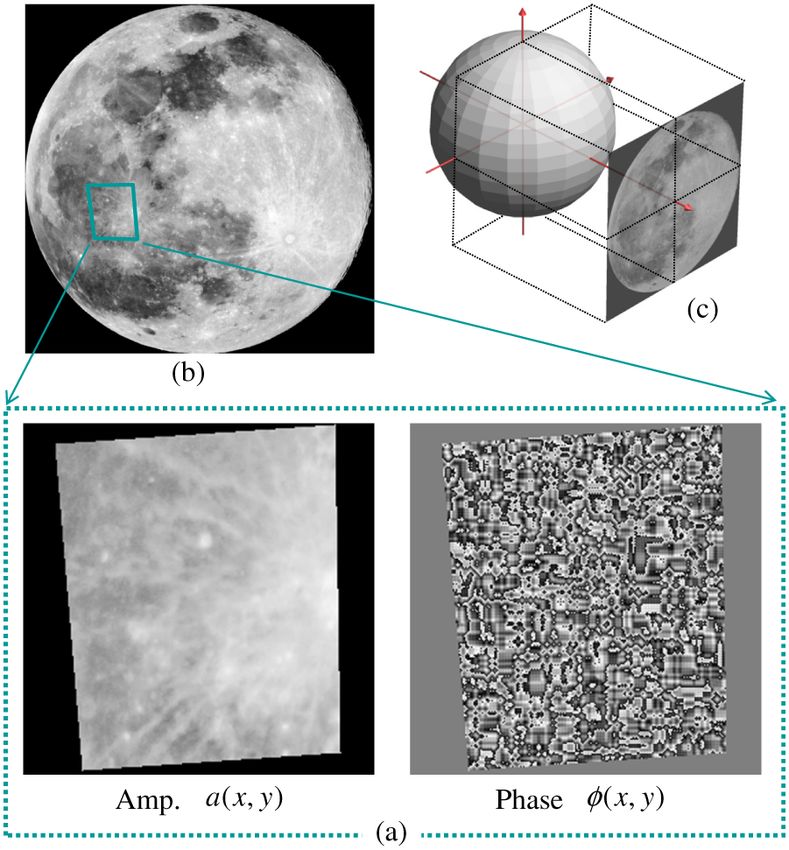
Matsushima, Nishi, and Nakahara: Simple wave-field rendering : : :

                                          Normal
                 Object surface           vector

                                            θn

                                           ψd

                                                                     Hologram

                    Fig. 5 Radiometric model of reconstructed polygon surfaces.

                                                         σa2n ðxn ; yn Þ
                                    Ln ðxn ; yn Þ ≃                      ;               (2)
                                                      π tan2 ψ d cos θn

                where an ðxn ; yn Þ is again the amplitude distribution of the
                surface function whose sampling density is given by σ.
                The normal vector of the polygon n forms the angle θn                                Fig. 7 Examples of the surface function for flat shading (a) and
                                                                                                     Gouraud shading (b).
                with the optical axis as shown in Fig. 5. Here, we assume
                that the polygon field is approximately spread over the
                solid angle π tan2 ψ d by the wide band phase distribu-                              process of the fringe pattern; it is fitted to the optical recon-
                tion ϕðxn ; yn Þ.                                                                    struction of the fabricated hologram.
                   The surface brightness given by relation (2) becomes infi-                           As a result, the wave-field rendering of diffused surfaces
                nite in the limit θn → π∕2; i.e., the brightness diverges                            is given by
                because it is assumed in the analysis that the hologram
                can reconstruct light in an unlimited dynamic range. How-                            an ðxn ;yn Þ
                ever, the dynamic range of the reconstructed light is actually                            s ffiffiffiffiffiffiffiffiffiffiffiffiffiffiffiffiffiffiffiffiffiffiffiffiffiffiffiffiffiffiffiffiffiffiffiffiffiffiffiffiffiffiffiffiffiffiffiffiffiffiffiffiffiffiffiffiffiffiffiffiffiffiffiffiffiffiffiffiffiffiffiffiffiffiffiffiffiffiffiffiffiffiffiffiffiffiffiffiffiffiffiffiffiffiffiffiffiffiffi
                                                                                                                                                                                                              ffi
                limited in real holograms because the fringe patterns are                                        cos θn þ γ
                                                                                                      ¼                                I shape;n ðxn ;yn ÞI shade;n ðxn ;yn ÞI tex;n ðxn ;yn Þ;
                never printed in full contrast of transmittance or reflectance                                       1þγ
                and are commonly quantized; e.g., the fringe pattern is binar-
                                                                                                                                                                                                           (5)
                ized in our case. Therefore, we adopt the following simpli-
                fied and non-divergent formula to estimate the brightness.                           where L0 ≡ 1 and the brightness I n ðxn ; yn Þ of Eq. (3) is
                                                                                                   replaced by the product of three distributions,
                                                    1þγ                                              I shape;n ðxn ; yn Þ, I shade;n ðxn ; yn Þ and I tex;n ðxn ; yn Þ, which are
                            I n ðxn ; yn Þ ¼ L0              a2 ðx ; y Þ;  (3)
                                                  cos θn þ γ n n n                                   given in local coordinates for each polygon and perform
                                                                                                     the roles of shaping polygons and shading and texture-
                                                          σ                                          mapping surfaces, respectively.
                                             L0 ¼                ;                       (4)
                                                      π tan2 ψ d
                                                                                                     3.2 Shaping and Shading
                where both L0 and γ are constants. The constant γ is intro-                          The shape of a polygon is given by the amplitude pattern of
                duced a priori to avoid the divergence of brightness. This                           the surface function of Eq. (1). Thus, the distribution that
                constant should be determined depending on the printing                              provides shape to the polygon is given by

                                           (a) near                                                (b) far

                Fig. 6 Photographs of the optical reconstruction of a polygon-based high-definition computer hologram named “Moai II”.2 The camera is focused on
                the near moai (a) and far moai (b).

                Journal of Electronic Imaging                                               023002-4                                                                      Apr–Jun 2012/Vol. 21(2)

Downloaded From: https://www.spiedigitallibrary.org/journals/Journal-of-Electronic-Imaging on 04 Jul 2021
Terms of Use: https://www.spiedigitallibrary.org/terms-of-use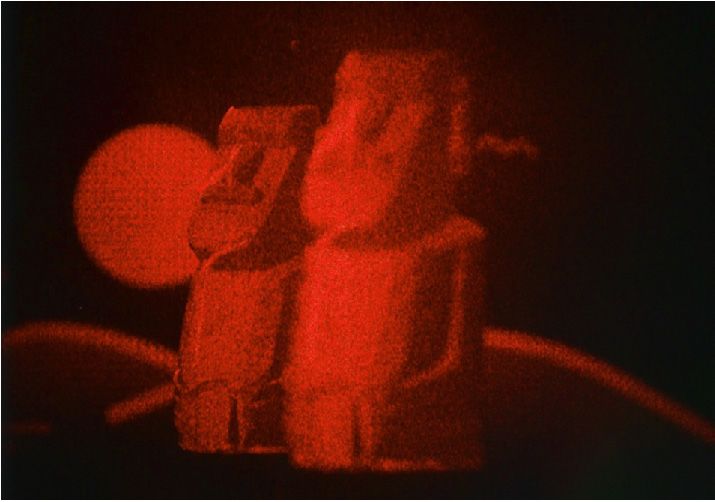
Matsushima, Nishi, and Nakahara: Simple wave-field rendering : : :


                                                      1   :::      inside polygon                    3.3 Texture Mapping
                         I shape;n ðxn ; yn Þ ¼                                   :       (6)
                                                      0   :::     outside polygon                    Texture mapping is carried out in the polygon-based method
                                                                                                     simply to provide the distribution I tex;n ðxn ; yn Þ using some
                In the polygon-based method, the shading technique for the                           projection of the texture image onto the polygon. An exam-
                object surface is essentially the same as that of CG. The dis-                       ple of the surface function for texture mapping is shown in
                tribution for shading is given by                                                    Fig. 9(a). Here, the object is a sphere and the mapping image
                                                                                                     is an astrophotograph of the real moon shown in (b). The
                                 I shade;n ðxn ; yn Þ ¼ I s;n ðxn ; yn Þ þ I env ;        (7)        distribution I tex;n ðxn ; yn Þ of the polygon n is provided by sim-
                                                                                                     ple orthogonal projection and interpolation of the astropho-
                                                                                                     tographic image as in (c).
                where I env gives the degree of ambient light. When flat-
                shading is used, the distribution I s;n ðxn ; yn Þ is a constant
                and given by Lambert’s cosine law:                                                   4 Creation of Computer Holograms
                                                                                                     Two high-definition computer holograms named “The
                                          I s;n ðxn ; yn Þ ≡ Nn · Li ;                    (8)        Moon” and “Shion” were created using the proposed tech-
                                                                                                     niques. The two holograms have the same number of pixels;
                                                                                                     that is, approximately nine billion pixels. The parameters
                where Nn and Li are the normal vector of the polygon n and a                         used in creating these holograms are summarized in Table 1.
                unit vector pointing from the surface to the virtual light                               The fringe patterns of the holograms were printed on
                source of the 3D scene.                                                              photoresist coated on ordinary photomask blanks by employ-
                    Our previous computer holograms such as “The Venus”1                             ing DWL-66 laser lithography system made by Heidelberg
                or “Moai I/II”2 were created by flat shading; i.e., using                            Instruments GmbH. After developing the photoresist, the
                the amplitude pattern given by Eqs. (5) to (8). As a result,                         chromium thin film was etched by using the ordinary process
                the borders of the polygons are visible in the optical                               for fabricating photomasks and formed the binary transmit-
                reconstruction as shown in Fig. 6. This problem is attributed                        tance pattern. As a result, the fabricated holograms have
                to the shading technique used.                                                       fringes of binary amplitudes.
                    Well-known smooth shading techniques of CG, such as
                Gouraud and Phong shading, are also applicable to wave-
                field rendering. The distribution I s;n ðxn ; yn Þ is not a constant                 4.1 The Moon
                but a function of the local coordinates ðxn ; yn Þ in these cases.                   The Moon is a computer hologram created using the techni-
                For example, Gouraud shading determines the local bright-                            ques of texture mapping and flat shading. The 3D scene is
                ness within a polygon through linear interpolation of the                            shown in Fig. 10. The main object is a sphere composed of
                brightness values at vertexes of the polygon. Thus, the                              1600 polygons. The diameter of the sphere is 55 mm. The
                local brightness is the same either side of the border of                            mapping image is again an astrophotograph of the real moon
                two polygons.                                                                        shown in Fig. 9(b). The background of this hologram is not a
                    Figure 7 compares surface functions for flat and smooth                          2D image but 300 point sources of light. Since the intention
                shading. The phase distribution of smooth shading in (b) is                          is that this background is to appear as stars in space, the
                the same as that of flat shading in (a), but the amplitude dis-
                tribution in (b) is given by the same technique as used in
                Gouraud shading in CG. Figure 8 shows the simulated recon-
                struction of a computer hologram of twin semi-spheres cre-
                ated with flat and Gouraud shading. Here, each semi-sphere
                is composed of 200 polygons and is 23 mm in diameter. The
                hologram dimensions are 65;536 × 32;768 pixels. The tech-
                nique of numerical image formation29 based on wave-optics
                was used for the simulated reconstruction. It is verified that
                the seams of polygons are no longer visible for the left sphere
                (a) created using the same technique as used in Gouraud
                shading.

                             (a) Smooth                                (b) Flat
                                                                                                     Fig. 9 (a) Example of the surface function for texture mapping. An
                Fig. 8 Simulated reconstruction of spheres rendered by Gouraud                       astrophotograph (b) is mapped onto the polygon-mesh sphere by
                shading (a) and flat shading (b).                                                    orthogonal projection of the mapping image (c).

                Journal of Electronic Imaging                                               023002-5                                            Apr–Jun 2012/Vol. 21(2)

Downloaded From: https://www.spiedigitallibrary.org/journals/Journal-of-Electronic-Imaging on 04 Jul 2021
Terms of Use: https://www.spiedigitallibrary.org/terms-of-use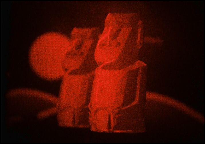
Matsushima, Nishi, and Nakahara: Simple wave-field rendering : : :
Table 1 Summary of parameters used in creating computer holograms “The Moon” and “Shion”.
The Moon Shion
Total number of pixels 8.6 × 10⁹ (131; 072 × 65; 536)
Number of segments 4×2
Reconstruction wavelength 632.8 nm
Pixel pitches 0.8 μm × 1.0 μm 0.8 μm × 0.8 μm
Size of hologram 104.8 × 65.5 mm2 104.8 × 52.4 mm2
Size of main object (W × H × D) 55 mm in diameter 60 × 49 × 28 mm3
Number of polygons (front face only) 776 2702
Background object 300 point sources of light 2356 × 1571 pixel image
Size of background object (W × H × D) 300 × 180 × 150 mm3 84 × 56 mm2
Rendering parameters (γ, I env ) 0.3, 0.2 0.01, 0.3
of polygons are noticed slightly because of the flat shading
of the sphere.
4.2 Shion
Shion is a hologram that reconstructs the live face of a girl.
However, the recording of the light emitted from the live face
does not have the same meaning as in classical holography.
Instead of recording the wave field of the face, the 3D shape
of the face was measured using a 3D laser scanner. The poly-
gon mesh measured using a Konica Minolta Vivid 910
device is shown in Fig. 12(a). The photograph simulta-
neously taken by the 3D scanner was texture-mapped to
the polygon-mesh surface, as shown in (b). The object is
Fig. 10 3D scene of “The Moon”. also shaded using Gouraud shading and placed 10 cm behind
the hologram. In addition, a digital illustration is arranged
12 cm behind the face object to make the background.
position and amplitude of these point sources are given by a The optical reconstruction of Shion is shown in Fig. 13
random-number generator. (Video 2) and Fig. 14 (Video 3). The seams of polygons are
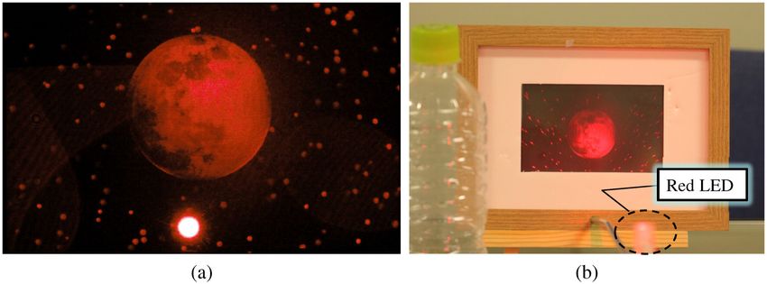
The optical reconstruction of The Moon is shown in no longer perceived because of the implementation of
Fig. 11 and Video 1. Since the light of the background smooth shading. However, there is occlusion error at the
stars is shielded by the silhouette of the moon object, the edge of the face object. This is most likely attributed to
hologram produces a strong perspective sensation. Seams the use of a silhouette to mask the field behind the object.
Fig. 11 Optical reconstruction of “The Moon” by using transmitted illumination of a He-Ne laser (a) and reflected illumination of an ordinary red LED
(b) (Video 1, WMV, 7.8 MB). The sphere object is rendered using texture mapping and flat shading.
Journal of Electronic Imaging 023002-6 Apr–Jun 2012/Vol. 21(2)
Downloaded From: https://www.spiedigitallibrary.org/journals/Journal-of-Electronic-Imaging on 04 Jul 2021
Terms of Use: https://www.spiedigitallibrary.org/terms-of-use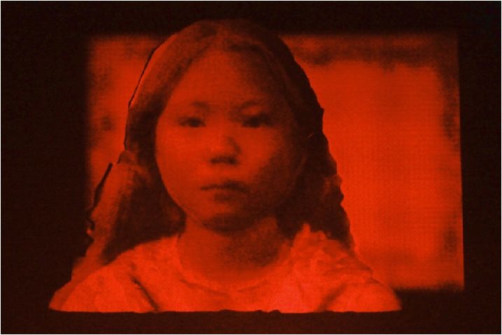
Matsushima, Nishi, and Nakahara: Simple wave-field rendering : : :

                Fig. 12 Polygon mesh of a live face whose shape is measured using a 3D laser scanner (a), and its rendering with CG using texture mapping.

                                            (a) left                                                 (b) right

                 Fig. 13 Optical reconstruction of the polygon-based high-definition computer hologram named “Shion” by using transmitted illumination of a He-Ne
                 laser (Video 2, WMV, 8.8 MB). The polygon-modeled object is rendered by texture mapping and Gouraud shading. Photographs (a) and (b) are
                 taken from different viewpoints.

                                                                                                     billions of pixels and reconstruct true fine 3D images that
                                                                                                     convey a strong sensation of depth. These 3D images are pro-
                                                                                                     duced only as still images at this stage, because current video
                                                                                                     display devices do not have sufficient display resolution
                                                                                                     for optical reconstruction. However, the results presented
                                                                                                     indicate what 3D images may be realized beyond Super
                                                                                                     Hi-Vision.

                                                                                                     Acknowledgments
                                                                                                     The authors thank Prof. Kanaya of Osaka University for his
                                                                                                     assistance in the 3D scan of live faces. The mesh data for the
                                                                                                     moai objects were provided courtesy of Yutaka_Ohtake by
                                                                                                     the AIM@SHAPE Shape Repository. This work was sup-
                                                                                                     ported in part by research grants from the JSPS (KAKENHI,
                Fig. 14 Optical reconstruction of “Shion” by using an ordinary red
                LED (Video 3, WMV, 10.8 MB).                                                         21500114) and Kansai University (Grant-in-aid for Joint
                                                                                                     Research 2011–2012).

                Since the object shape is complicated, the simple silhouette                         References
                does not work well for light-shielding.
                                                                                                      1. K. Matsushima and S. Nakahara, “Extremely high-definition full-
                                                                                                         parallax computer-generated hologram created by the polygon-based
                5 Conclusion                                                                             method,” Appl. Opt. 48(34), H54–H63 (2009).
                                                                                                      2. K. Matsushima and S. Nakahara, “High-definition full-parallax CGHs
                Simple rendering techniques were proposed for photorealis-                               created by using the polygon-based method and the shifted angular
                tic reconstruction in polygon-based high-definition computer                             spectrum method,” in Proc. SPIE 7619, 761913 (2010).
                holography. The polygon-based method has similarities with                            3. K. Matsushima, M. Nakamura, and S. Nakahara, “Novel techniques
                                                                                                         introduced into polygon-based high-definition CGHs,” in OSA Topical
                common techniques used in CG. Exploiting this similarity,                                Meeting on Digital Holography and Three-Dimensional Imaging, Opti-
                smooth shading and texture mapping are applicable to ren-                                cal Society of America, JMA10 (2010).
                                                                                                      4. K. Matsusima et al., “Computational holography: real 3D by fast wave-
                dering surface objects in almost the same manner as in CG.                               field rendering in ultra-high resolution,” in Proc. SIGGRAPH Posters’
                The created high-definition holograms are composed of                                    2010, Association for Computer Machinery (2010).

                Journal of Electronic Imaging                                               023002-7                                                Apr–Jun 2012/Vol. 21(2)

Downloaded From: https://www.spiedigitallibrary.org/journals/Journal-of-Electronic-Imaging on 04 Jul 2021
Terms of Use: https://www.spiedigitallibrary.org/terms-of-use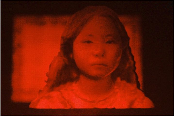
Matsushima, Nishi, and Nakahara: Simple wave-field rendering : : :

                 5. H. Nishi et al., “New techniques for wave-field rendering of polygon-            27. R. P. Muffoletto, J. M. Tyler, and J. E. Tohline, “Shifted Fresnel dif-
                    based high-definition CGHs,” in Proc. SPIE 7957, 79571A (2011).                      fraction for computational holography,” Opt. Express 15(9),
                 6. DigInfo., “Computer-synthesized holograms—the ultimate in 3D                         5631–5640 (2007).
                    images” http://www.diginfo.tv/2010/07/22/10-0130-r-en.php.                       28. K. Matsushima, “Shifted angular spectrum method for off-axis numer-
                 7. K. Matsushima, “Computer-generated holograms for three-dimensional                   ical propagation,” Opt. Express 18(17), 18453–18463 (2010).
                    surface objects with shade and texture,” Appl. Opt. 44(22), 4607–4614            29. K. Matsushima and K. Murakami, “Numrical image formation and their
                    (2005).
                 8. J. P. Waters, “Holographic image synthesis utilizing theoretical meth-               application to digital holography and computer holography,” to be sub-
                                                                                                         mitted to Opt. Express.
                    ods,” Appl. Phys. Lett. 9(11), 405–407 (1966).
                 9. A. D. Stein, Z. Wang, and J. J. S. Leigh, “Computer-generated holo-
                    grams: a simplified ray-tracing approach,” Comput. Phys. 6(4),
                    389–392 (1992).
                10. M. Lucente, “Interactive computation of holograms using a look-up                                          Kyoji Matsushima received his BE, ME and
                    table,” J. Electronic Imaging 2(1), 28–34 (1993).                                                          PhD degree of applied physics from Osaka
                11. A. Ritter et al., “Hardware-based rendering of full-parallax synthetic                                     City University (Japan). Matsushima joined
                    holograms,” Appl. Opt. 38(8), 1364–1369 (1999).                                                            Department of Electrical Engineering and
                12. K. Matsushima and M. Takai, “Recurrence formulas for fast creation of                                      Computer Science at Kansai University as a
                    synthetic three-dimensional holograms,” Appl. Opt. 39(35), 6587–6594                                       research assistant in 1990. He is currently a
                    (2000).                                                                                                    professor in the Department of Electrical and
                13. H. Yoshikawa, S. Iwase, and T. Oneda, “Fast computation of Fresnel                                         Electronic Engineering in the same university.
                    holograms employing difference,” in Proc. SPIE 3956, 48–55 (2000).                                         His research interests include 3D imaging
                14. N. Masuda et al., “Computer generated holography using a graphics
                    processing unit,” Opt. Express 14(2), 603–608 (2006).                                                      based on computer-generated holograms
                15. Y. Ichihashi et al., “HORN-6 special-purpose clustered computing                                           and digital holography, and numerical simula-
                    system for electroholography,” Opt. Express 17(16), 13895–13903                  tions in wave optics.
                    (2009).
                16. L. Ahrenberg et al., “Computer generated holograms from three dimen-
                    sional meshes using an analytic light transport model,” Appl. Opt.
                    47(10), 1567–1574 (2008).                                                                                  Hirohito Nishi received his BE in electrical
                17. H. Kim, J. Hahn, and B. Lee, “Mathematical modeling of triangle-                                           engineering and computer science and ME
                    mesh-modeled three-dimensional surface objects for digital hologra-                                        in electrical and electronic engineering from
                    phy,” Appl. Opt. 47(19), D117–D127 (2008).                                                                 Kansai University. He is currently a graduate
                18. K. Matsushima and A. Kondoh, “A wave-optical algorithm for hidden-                                         student of Kansai University. His current inter-
                    surface removal in digitally synthetic full-parallax holograms for three-
                    dimensional objects,” in Proc. SPIE 5290(6), 90–97 (2004).                                                 ests include 3D imaging based on computer-
                19. A. Kondoh and K. Matsushima, “Hidden surface removal in full-                                              generated holograms.
                    parallax CGHs by silhouette approximation,” Syst. Comput. Jpn. 38(6),
                    53–61 (2007).
                20. M. Janda, I. Hanák, and L. Onural, “Hologram synthesis for photorea-
                    listic reconstruction,” J. Opt. Soc. Am. A 25(12), 3083–3096 (2008).
                21. H. Nishi, K. Matsushima, and S. Nakahara, “A novel method for ren-
                    dering specular and smooth surfaces in polygon-based high-definition
                    CGH,” in OSA Topical Meeting on Digital Holography and Three-
                    Dimensional Imaging 2011, Optical Society of America, JDWC29
                    (2011).                                                                                                Sumio Nakahara is an associate professor
                22. H. Nishi, K. Matsushima, and S. Nakahara, “Rendering of specular
                    surfaces in polygon-based computer-generated holograms,” Appl. Opt.                                    in the Department of Mechanical Engineering
                    50(34), H245–H252 (2011).                                                                              in Kansai University (Japan). His PhD degree
                23. K. Matsushima, H. Schimmel, and F. Wyrowski, “Fast calculation                                         is from Osaka University in 1987. He joined
                    method for optical diffraction on tilted planes by use of the angular                                  Department of Mechanical Engineering at
                    spectrum of plane waves,” J. Opt. Soc. Am. A20(9), 1755–1762 (2003).                                   Kansai University as a research assistant
                24. K. Matsushima, “Formulation of the rotational transformation of wave                                   in 1974. He was adjunct professor position
                    fields and their application to digital holography,” Appl. Opt. 47(19),                                at Washington State University, Pullman,
                    D110–D116 (2008).                                                                                      Washington, in 1993–1994. His current
                25. J. W. Goodman, Introduction to Fourier Optics, 2nd ed., Chapter 3.10,
                    McGraw-Hill, New York (1996).                                                                          research interests are in the development
                26. K. Matsushima and T. Shimobaba, “Band-limited angular spectrum                                         of laser direct-write lithography technology
                    method for numerical simulation of free-space propagation in far                 for computer-generated holograms, laser micro processing and
                    and near fields,” Opt. Express 17(22), 19662–19673 (2009).                       MEMS technology.

                Journal of Electronic Imaging                                               023002-8                                                 Apr–Jun 2012/Vol. 21(2)

Downloaded From: https://www.spiedigitallibrary.org/journals/Journal-of-Electronic-Imaging on 04 Jul 2021
Terms of Use: https://www.spiedigitallibrary.org/terms-of-use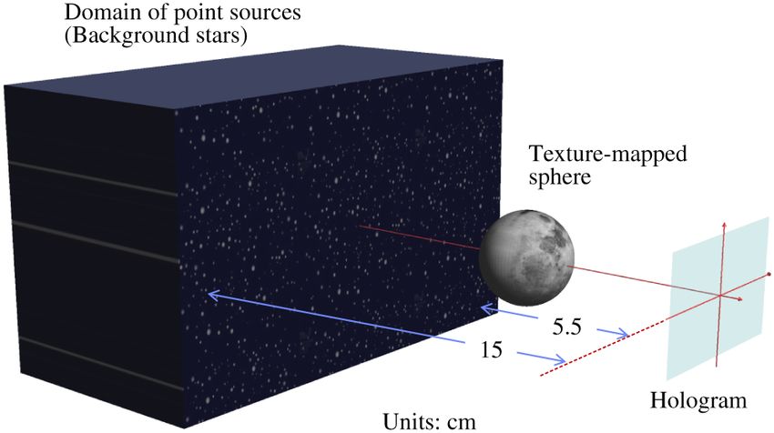
You can also read