A Seamless Model-Based Development Process for Automotive Systems
←
→
Page content transcription
If your browser does not render page correctly, please read the page content below
A Seamless Model-Based Development Process for
                     Automotive Systems∗

                          Jörg Holtmann, Jan Meyer, Matthias Meyer
                 s-lab – Software Quality Lab, Software Engineering Group,
                       Heinz Nixdorf Institute, University of Paderborn
                       Warburger Str. 100, 33098 Paderborn, Germany
                           [jholtmann|jmeyer|mmeyer]@s-lab.upb.de

       Abstract: Safety critical functions for embedded systems are increasingly realized
       with software. Current and future standards and maturity models impose high accu-
       racy and quality for the development process of such software-intensive, embedded
       systems. But nowadays, there are process and tooling gaps between different model-
       ing aspects for the system under development (SUD). Furthermore, the SUD is usually
       verified and validated not until it is completely implemented, which leads to expensive
       corrections. In this paper we present a seamless, model-based development process,
       which is intended for the automotive supplier domain and conforms to the process
       reference model of Automotive SPICE R 1 . The development process addresses the
       issues mentioned above by using systematic transitions between different modeling
       aspects and simulations in early development stages.

1    Introduction

It is no longer possible to imagine our daily lifes without embedded systems. They can be
found in different products ranging from home appliances to complex transport systems.
The part of functionality realized by software steadily increases in these systems. Conse-
quently, also the number of safety critical functions realized by software grows, especially
in the automotive sector.
To achieve high-quality software components realizing such functions, specific procedures
are necessary. On the one hand, in addition to functional requirements there are safety
requirements that must be fulfilled by a safety-critical component. These safety require-
ments can be derived from international standards like the IEC 61508 or, for the automo-
tive industry, the upcoming standard ISO 26262. For example, for a component with a
high automotive safety integrity level (ASIL), the data exchange via its interfaces has to
be secured using CRC-checksums. Such safety requirements are, however, not restricted
to the system under development (SUD) but also concern the development process. The
fulfillment of the safety standards is mandatory by law.
  ∗ This work was partially funded by the German Federal Ministry of Education and Research (BMBF), grant

“SPES2020, 01IS08045H”.
   1 Automotive SPICE R is a registered trademark of the Verband der Automobilindustrie e.V. (VDA).
On the other hand, the conformity to maturity models is a competitive advantage. In the automotive domain, the original equipment manufacturer (OEM) often requests a certain level of the Automotive SPICE R maturity model for their suppliers. In addition to the requirements imposed by safety standards, the process reference model of Automotive SPICE R [Aut10] demands properties like traceability and defines development stages as well as resulting artifacts. But since standards and process reference models have to be generally applicable to a broad range of organizations, they do not specify how the realization of the properties or artifacts can be achieved. Models have found their way into current development processes of embedded systems, also in the automotive sector. However, often different specialized models for specific as- pects are used at different development stages with varying abstraction levels in a fractal way [TRS+ 10, Bro06]. This leads to several problems. First of all, there are process and tooling gaps between these models. It is unclear how to move from, for example, tex- tual requirements to model-based design [WW03] and from the system architecture to the software architecture [DN08]. Thus, there is a need for integrated model chains [Bro06]. Second, traceability between different models and between models and requirements is nowadays established by manually linking the individual model elements and require- ments. As the amount of requirements and hence the size of the models grow, the lack of automation for this task is increasingly a problem. Third, there is no guidance which mod- els have to be used at a specific development stage [TRS+ 10]. Process reference models are too general to help on this problem, so a concrete development process is necessary. In this paper, we address these problems by defining a seamless, model-based develop- ment process conforming to Automotive SPICE R , which uses systematic and partially automated transitions between different modeling perspectives. Since embedded systems consist of hardware and software parts, the interaction between these diverse elements is often not tested until the end of the development process when all software and hardware components are available. If there are errors in the SUD, their correction is very expensive. Thus, a verification and validation (V&V) of the design deci- sions in early development stages is necessary. We will show, how the system architecture can be extended to include all necessary information for simulations of the SUD already in early stages of our development process. As an ongoing example for an embedded system we are using a comfort control unit. This electronic control unit (ECU) is responsible for the control of the interior light, the central locking, and the adjustment of windows, mirrors, and seats. The comfort control unit is not a high-grade safety-critical system, but it is in connection with other systems that have a high safety level. Thus, it also contains some functions to check the interior whether persons are aboard. This information is necessary for the airbag system. Since this is a high-grade safety-critical system, the comfort control unit (as it is a data provider) has also a classification as a safety-critical system. In the next section we present a systematic development process for the automotive sup- plier domain and show the different artifacts, extensions, techniques, and their usage in the development process. In Section 3 the related work is discussed. At the end of the paper a conclusion and an outlook is presented.
2     Seamless Model-Based Development of Automotive Systems

We base our systematic development process for automotive systems on the Automotive
SPICE R process reference model (PRM), which defines ten so-called engineering pro-
cesses (ENG). Figure 1 depicts those processes organized in a V-Model. In the following
three subsections we present techniques supporting the engineering processes in the left
part of the V-Model. Additionally, these techniques will be associated with modeling
              Entwicklungsprozess
perspectives similar to the ones defined in [TRS+ 10]. These perspectives cover different
modeling aspects of the SUD and thus serve as means to achieve separation of concerns.

                ENG.1/2 System Requirem. Analysis                                                   ENG.10 System Testing

                    ENG.3 System Architect. Design                                           ENG.9 System Integration Test

                        ENG.4               ENG.4                                       ENG.8                 ENG.8
                         HW-Requirem.        SW-Requirem.                             Software               Hardware
                          A l i
                          Analysis            A l i
                                              Analysis                               T ti
                                                                                     Testing               Testing
                                                                                                           T  ti

                                  ENG.5              ENG.5                         ENG.7                 ENG.7
                                   Hardware           Software                Software              Hardware
                                    Design             Design             Integration Test      Integration Test

                                                                           Module Test
                                                                 ENG.6                       Module Test
                                                            Software Construction
                                                                                                                             Software focus
                                                         ENG 6 Hardware Construction
                                                         ENG.6                                                               Hardware focus

Figure 1: A development process from the automotive supplier domain following the Automotive
SPICE R process reference model

The development starts with informal textual requirements on OEM side                  Quelle: (ENG.1).
                                                                                               Hella      Our
     © Softwarestarts
approach        Quality Lab (s-lab) the manual creation of formalized, textual requirements, their
                          with                                                                       7 valida-
tion, and the transition to the model-based system architectural design (cf. Subsection 2.1).
Thus, this subsection covers the engineering process ENG.2 and the transition to ENG.3.
In ENG.3 the system architecture including a first specification of the operating system
(OS) is done. It can be simulated wrt. real-time and resource requirements (cf. Subsection
2.2). Later it is enriched with further details like a first estimation for software resource
consumption (ENG.4 and ENG.5). Finally, the transition from the architecture model to
the software design specified with the the architecture framework and standard AUTOSAR
[AUT09] is ensured by using model transformation and code synthesis techniques (ENG.5
and ENG.6), which is presented in Subsection 2.3. Furthermore, we present a simulation
for the AUTOSAR model additional to the simulation in 2.2.

2.1   Formalization of requirements and transition to model-based design

As stated in the introduction, model-based design is applied in current development pro-
cesses for automotive systems. In contrast, requirements for them are nowadays mainly
specified in unrestricted natural language. This is due to the fact that natural language is
easy to use, because it does not require training or dedicated tools [Poh10], so all stake-
holders can understand requirements formulated in this way. But since unrestricted natural
language is informal and ambiguous, such requirements cannot be automatically processed
without resolving the ambiguity by hand. Thus, all further tasks like the validation of the
requirements, the transition to the model-based design, and the maintenance of traceability
have to be done manually, which is time-consuming, error-prone, and often repetitive.
Figure 2 sketches the requirements engineering within our development process. In the
automotive domain mostly informal customer requirements (e.g., unrestricted natural text,
drawings) as well as a communication matrix containing the communication bus signals
to the surrounding systems are delivered by the OEM. The customer requirements specify
behavior that is observable by the end users (i.e., the car passengers), and thus reside in
the user perspective. From the viewpoint of the supplier, this is the Automotive SPICE R
engineering process ENG.1 (requirements elicitation, cf. Figure 1). In the process of sys-
tem requirements analysis (ENG.2), these customer requirements are manually analyzed
by the supplier and system requirements are created, which propose a possible solution
offering the required system functionality. Thus, this process belongs to the functional
perspective. The system requirements analysis is one of the most important engineering
processes, since the system requirements serve as basis for all further engineering pro-
cesses [HMDZ08].
User Perspective Functional Perspective
(OEM)
Automated Architectural Model
Customer Requirements
Validation
System Requirements System Analysis Model
Requirement Patterns
bdd Comfort Control Unit
• The system “Comfort Control
Unit” consists of the following Req2Sys
«block» «block» ...
A comfort control unit has to subsystems: Central Locking, Central Locking Comfort Control Unit
be created that interconnects Interior Light Control, … .
the functionalities of the • The system “Interior Light
central locking system, the Control” processes the Doors_Unlocked
«block»
Request_Switch_Reading_Light_F
interior light control, … . following signals: Request_Switch_Reading_Light_R
Interior Light Control
Doors_Unlocked, …
System
Requirements
Analysis
Figure 2: Requirements engineering using requirement patterns
To overcome the problems caused by the use of natural language for the formulation of
requirements, we propose a controlled natural language (CNL) approach for the specifica-
tion of functional system requirements in the automotive domain. The CNL restricts the
expressiveness of natural language and disambiguates it, enabling automatic processing
of the requirements while having textual requirements understandable for all stakehold-
ers at the same time. We use a slightly extended CNL called requirement patterns that
is already successfully used in the automotive industry [KK06]. Requirements specified
with this CNL describe a subsystem and function hierarchy including required inputs and
provided outputs for the subsystems and functions. For example, the system requirements
in Figure 2 specify that the Comfort Control Unit contains the subsystem Interior Light Con-
trol (among others), which reacts to the signal Doors Unlocked. Furthermore, a manual
mapping of such logical signals to the technical signals of the communication matrix iscreated. By this means it is checked whether all required information is delivered by the surrounding systems. Firstly, the possibility of automatically processing the system requirements formulated with the requirement patterns enables to use an automated requirements validation. The validation detects requirements that violate rules for the function hierarchy (like unused signals, a not-well-formed function hierarchy, overlapping (de-)activation conditions for functions, range violations) and proposes corrections [HMvD11]. Secondly, by using pars- ing and model transformation techniques, we can transfer the information already con- tained by the system requirements to an initial system analysis model (cf. Req2Sys in Figure 2). This is the starting point of the model-based design and subject of further man- ual refinement. For example, the subsystems have been translated to SysML blocks whose hierarchical relationships are shown by a block definition diagram. The model transforma- tions are realized in a research prototype and base on bidirectional Triple Graph Grammars (TGGs) [Sch95], which allow—besides the transformation to SysML—synchronization of system requirements and system analysis model as well as a translation to the text back again, if combined with code synthesis techniques. Additionally, since the transforma- tion relates the requirements with the model elements, we automatically gain traceability. Further details are given in [Hol10]. 2.2 Modeling and simulation of the system architecture The next step in the development process according to Automotive SPICE R is the creation of the system architecture design. This corresponds to the engineering process ENG.3 of the Automotive SPICE R PRM (see Figure 1). We use the systems modeling language (SysML) to specify the hardware and software subsystems including their interrelations. Additionally, in this engineering step the decision has to be made which functions will be implemented in hardware and which will be implemented in software [HMDZ08]. As in- put the system requirements and the system analysis model from the system requirements analysis are used and refined in a manual way to get the system architecture design. Figure 3 depicts our view on the system architecture design as part of the architecture model. In the example, the Interior Light Control subsystem has been refined to contain three parts with the stereotype AtomicSWC (necessary for the model transformation described in the next subsection), as shown by the internal block diagram (ibd Interior Light Control). Besides the structural view of the system, its behavior has to be specified, too. For em- bedded systems, the behavior is often characterized by timing requirements. Since SysML is lacking appropriate means to specify timed behavior, we extended SysML by Real- Time Statecharts (RTSCs) [HMSN10]. RTSCs extend the UML/SysML State Machines on the basis of Timed Automata, which facilitates to model reactive and timed behavior in a formal way. Additionally, RTSCs can be formally verified on fulfillment of timing requirements. One example for a timing requirement of the comfort control ECU is: “The interior light has to be on for 3000 ms after the doors are unlocked.” The RTSC repre- senting this informal requirement is shown in Figure 3. It contains two states representing Light on and Light off. Upon receiving a Doors Unlocked event, the light is switched on or
Functional Perspective Logical/Technical Perspective
Architectural Model
System Architecture Design
System Analysis Model
bdd Comfort Control Unit
ibd Interior Light Control Real-Time Statecharts
Doors_Unlocked/
Request_Switch_
«block» «block» ... Request_Switch_ Reading_Light_F
Central Locking Comfort Control Unit Reading_Light_F «AtomicSWC»
Doors_Unlocked lcf: Light_Control_Front Light on
Light off
t0 ≥ 3000
entry: {t0} Doors_Unlocked/ entry: {t0}
Doors_Unlocked
«block»
Request_Switch_Reading_Light_F Doors_Unlocked «AtomicSWC»
Interior Light Control
Request_Switch_Reading_Light_R lct: Light_Control_Trunk OS Properties
Doors_Unlocked
updateStatus()
Doors_Unlocked
System «AtomicSWC»
[1]
InteriorLight_Task
Request_Switch_ lcr: Light_Control_Rear
Architectural Design Reading_Light_R Request_Switch_ 10 ms [2]
switchOnOff()
Reading_Light_R 50 ms
Synthesis
Software Design
System Simulation Model
Application Software
Model
Transformation
AUTOSAR Simulation
uses
Runtime Environment
Basic Software
Synthesis
Figure 3: The system architecture design and its extensions, the transition to the software design,
and the usage of simulations
stays on. The clock variable t0 is used to express the timing: Light on may only be left
after 3000 ms (specified by the time invariant t0 ≥ 3000) and t0 is reset to 0 upon entering
one of the states (specified by entry : {t0 } in both states).
Since we want to allow an early verification of the system and the architectural deci-
sions taken so far, we include a system simulation already in this engineering process
(ENG.3), which allows to check, for example, whether the bus or CPU load is acceptable
and whether timing requirements are satisfied. The architectural model already contains
most of the information required for such a simulation. However, it requires additional
information concerning the configuration of the OS running on the ECUs.
In the automotive domain, the OS have no dynamic parts (e.g., OSEK OS). This means
that all OS settings are static and can be specified during the development phase. This
enables the modeling of OS properties in the architecture model. However, since the
SysML has no elements for the specification of OS properties, we extended it with a profile
to specify, for example, tasks with their priority and duration, the mapping of functions to
tasks, and their activation policies. The profile also supports the specification of resources,
alarms and interrupts. As an example, Figure 3 depicts a specification of the cyclic task
InteriorLight Task, which is triggered every 50 ms. Each time the task may run at most 10
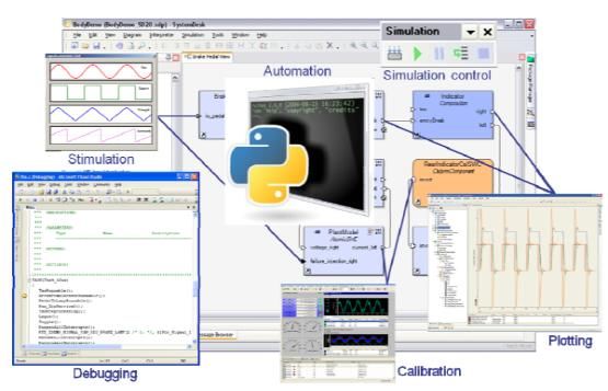
ms. During each run, it first executes the function updateStatus(), which checks the doorstatus and generates events upon a status change. Afterwards, the function switchOnOff() is called, which executes the RTSC depicted above. For the simulation, we use the real-time simulation tool chronSIM2 . The tool needs a dedicated simulation model, which contains information about the hardware architecture, the software components, the deployment of software to hardware, and the OS settings; that is, the information we specify in the extended architecture model. Thus, we use a model to text transformation to generate the necessary System Simulation Model for chronSIM as indicated in Figure 3. A detailed description of the transformation and how the simulation output looks like can be found in [NMK10]. The system architecture design covers different aspects of information and changes during the development process. In an early development stage (i.e., the beginning of ENG.3), the system architecture design is defined by a network of interacting logical components and thus belongs to the logical perspective. In later development stages (i.e., the end of ENG.3 to ENG.5), the system architecture design is enriched with technical information like hardware, deployment, and OS details and thus is covered by the technical perspective. 2.3 Transition from the system architecture to AUTOSAR A further gap in the development process exists between the system architectural design (ENG.3) and the software design (ENG.5). Automotive SPICE R demands another pro- cess between ENG.3 and ENG.5, namely the software requirements analysis (ENG.4). In ENG.4 the system requirements that are relevant for software elements are assigned to the individual software items and afterwards analyzed and refined, if required [HMDZ08]. Therefore, the system analysis model (cf. Figures 2 and 3) is refined with, for example, Activity, Sequence or (Real-Time) Statechart Diagrams. These requirements are used as an input for the software design (ENG.5), which we describe with AUTOSAR [AUT09]. An AUTOSAR architecture consists of three major layers. The first one contains the ap- plication software; that is, the application software components and their algorithms, it- self. The second layer is the so called Runtime Environment (RTE), which serves as a middleware for the communication of software components potentially located on differ- ent ECUs. The RTE is automatically created by code generators. The third layer is the so-called basic software, which contains partially hardware-dependent software providing basic services to the application software. Examples for the basic software are the OS or the communication stack, which is responsible for the communication to other ECUs. In order to establish a seamless development from the requirements via the architectural model to the software design, a further model transformation from the architectural model to AUTOSAR is necessary. Our transformation consists of two parts. In the first part, the structural elements like components with ports and connectors are transformed to AU- TOSAR [GHN10]. In Figure 3 this is shown with the arrow Model Transformation: the three parts lcf:Light Control Front, lct:Light Control Trunk, and lcr:Light Control Rear are transformed into atomic software components in AUTOSAR. Like the model transforma- 2 http://www.inchron.com/chronsim.html
tions between system requirements and system analysis model, the model transformations
between SysML and AUTOSAR application components base on TGGs. Their bidirec-
tional nature enables synchronization of both models and round-trip capabilities. This is
one of the major advantages over approaches using SysML and AUTOSAR in a comple-
mentary but manual way: if changes on one model occur, they can be transferred to the
other model automatically in order to reestablish consistency.
The second part is responsible for the configuration of the RTE and the basic software. The
functions like updateStatus() or switchOnOff() specified in the architectural model, can be
translated to so-called runnables in AUTOSAR. Those runnables are used in turn for the
RTE generation. This can also be done for further elements of the RTE like exclusive
areas, interrunnable variables, and so on. The configuration of the basic software can be
described by transforming the OS properties specified in the architectural model. In the
transformation step, the tasks from the architectural model are transformed to AUTOSAR
OS tasks. In the same way, more parts of the AUTOSAR basic software can be configured,
for example, the communication stack or parts of the memory stack. The transformation
closes the gap to the software design (ENG.5). The transition to software construction
(ENG.6) is done with the help of AUTOSAR code generators and by using the RTE API.
However, besides the automated model transformation, some manual refinements of the
AUTOSAR software architecture are still necessary, for example, the decision whether
implicit or explicit communication is used. Furthermore, the generated RTE has a big in-
fluence on the AUTOSAR software architecture. This is an additional layer that has to be
verified and validated in interaction with the application components and the basic soft-
ware. Consequently, another simulation is necessary to verify the AUTOSAR architecture.
For this purpose, we use the AUTOSAR authoring and simulation tool SystemDesk3 . This
simulation shows, whether the RTE is configured correctly and timing requirements are
still fulfilled. For example, it is verified whether the RTE can handle the application data
as fast as it is necessary to switch on the lights after a door is unlocked.

3   Related Work

There are some other approaches that deal with improving the development process in
the automotive domain and close the process gaps. In [Kor07] and [Bol09] a systematic
modeling with SysML and AUTOSAR is presented. The approaches suggest to use the
SysML and AUTOSAR in a systematic development process, like we do in our approach.
The gap between the two modeling languages is not closed by means of automatic model
transformations, but by manually establishing traceability. Therefore, the developer has to
manually model both architectures and afterwards create traceability links. This fulfills the
requirements of Automotive SPICE R , but it does not speed up the development process.
The tool platform EDONA [OT10] aims at integrating the architecture description lan-
guage EAST-ADL2 [ATE10] (also based on SysML and UML) and AUTOSAR by using
  3 http://www.dspace.com/en/pub/home/products/sw/system_architecture_

software/systemdesk.cfm
model transformations. A further aim related to our work is a simulation of generated
code including the OS properties. In contrast to our approach, EDONA focuses only on
techniques and tools but does not consider any process reference model. Furthermore,
the transition from textual requirements to the model-based design and the traceability be-
tween them is not addressed. Finally, the transition from the system model to AUTOSAR
encompasses only the component descriptions on the application layer. Thus, the genera-
tion of parts of the basic software configuration is not supported.

4   Conclusion and Outlook

In this paper we presented a seamless and systematic model-based development process
for automotive systems. We explained how system requirements written in natural lan-
guage can be formalized. This way, we enable an automated processing of the require-
ments; that is, a validation and the extraction of information into an initial system analysis
model, while all stakeholders are still able to understand them. Furthermore, we extended
the modeling languages with notations to specify timed behavior and OS properties. On
the one hand, this facilitates the generation of simulation models for V&V of the system
in early design stages. On the other hand, the extended architectural model enables the
transformation of architectural elements to an AUTOSAR model.
As explained in the introduction, Automotive SPICE R does not provide any guidelines
which modeling language shall be used in an engineering process for the creation of an
artifact. Thus, our development process can be seen as a possible instance of the Automo-
tive SPICE R PRM, which additionally provides guidance for the developers on moving
from the system requirements via the system architecture design and the software design
to the implementation. Furthermore, the presented simulation techniques allow the V&V
of the SUD at early design stages instead of implementing and afterwards verifying and
validating a complete prototype consisting of software and hardware. Thus, since errors
are detected earlier, this leads to less expensive corrections.
One of our further research goals is a tighter connection between the requirement patterns
and the system real-time simulation, so that the requirements can be used as direct input
for the simulation. Secondly, the requirement patterns describe a function hierarchy, but
currently we do not specify how a function shall work. When we extended the CNL in such
a way, it would be possible to check whether there is an already implemented component
that realizes the function—and hence boosting reuse of components. As we mentioned
the upcoming standard ISO 26262, another goal is to enhance our development process to
easily integrate techniques for ensuring functional safety. Finally, we want to extend our
current demonstrator models for a more extensive evaluation of the overall process.

References

[ATE10] ATESST2. EAST-ADL Domain Model Specification. Version 2.1 RC3, 2010.
[AUT09] AUTOSAR GbR. AUTOSAR Specification, 2009.
[Aut10]   Automotive Special Interest Group (SIG).      Automotive SPICE R : Process Refer-
          ence Model. Release v4.5, 2010.
[Bol09]   Richard F. Bolt. Modeling AUTOSAR systems with a UML/SysML profile. Technical
          report, IBM Software Group, Rational, 2009.
[Bro06]   Manfred Broy. Challenges in Automotive Software Engineering. International Confer-
          ence on Software Engineering (ICSE), 2006.
[DN08]    Marco Di Natale. Design and Development of Component-Based Embedded Systems for
          Automotive Applications. In Reliable Software Technologies – Ada-Europe 2008, volume
          5026 of LNCS, pages 15–29. Springer, 2008.
[GHN10] Holger Giese, Stephan Hildebrandt, and Stefan Neumann. Model Synchronization at
        Work: Keeping SysML and AUTOSAR Models Consistent. In Graph Transformations
        and Model-Driven Engineering, volume 5765 of LNCS, pages 555–579. Springer, 2010.
[HMDZ08] Klaus Hörmann, Markus Müller, Lars Dittmann, and Jörg Zimmer. Automotive SPICE
       in Practice: Surviving Implementation and Assessment. Rocky Nook, 2008.
[HMSN10] Jörg Holtmann, Jan Meyer, Wilhelm Schäfer, and Ulrich Nickel. Eine erweiterte Sys-
       temmodellierung zur Entwicklung von softwareintensiven Anwendungen in der Automo-
       bilindustrie. In Software Engineering 2010 – Workshopband, volume 160 of LNI, pages
       149–158. Bonner Köllen Verlag, 2010.
[HMvD11] Jörg Holtmann, Jan Meyer, and Markus von Detten. Automatic Validation and Correc-
       tion of Formalized, Textual Requirements. In Proceedings of the ICST Workshop Require-
       ments and Validation, Verification & Testing (ReVVerT 2011), 2011. Accepted.
[Hol10]   Jörg Holtmann. Mit Satzmustern von textuellen Anforderungen zu Modellen. OBJEKT-
          spektrum, RE/2010 (Online Themenspecial Requirements Engineering), 2010.
[KK06]    Roland Kapeller and Stefan Krause. So natürlich wie Sprechen - Embedded Systeme
          modellieren. Design & Elektronik, 08:64–67, 2006.
[Kor07]   Andreas Korff. AUTOSAR und UML – das passt. Automobil Elektronik, 2007.
[NMK10] Ulrich Nickel, Jan Meyer, and Tapio Kramer. Wie hoch ist die Performance? Automobil-
       Elektronik, 03:36 – 38, 2010.
[OT10]    François Ougier and François Terrier. Eclipse based architecture of the EDONA plat-
          form for automotive system development. In Proceedings of the European Congress on
          Embedded Real-Time Software and Systems (ERTS2 2010), 2010.
[Poh10]   Klaus Pohl. Requirements Engineering: Fundamentals, Principles, and Techniques.
          Springer, 2010.
[Sch95]   Andy Schürr. Specification of Graph Translators with Triple Graph Grammars. In Graph-
          Theoretic Concepts in Computer Science, volume 903 of LNCS, pages 151–163. Springer,
          1995.
[TRS+ 10] Judith Thyssen, Daniel Ratiu, Wolfgang Schwitzer, Alexander Harhurin, Martin Feilkas,
         and Eike Thaden. A System for Seamless Abstraction Layers for Model-based Develop-
         ment of Embedded Software. In Software Engineering 2010 – Workshopband, volume
         160 of LNI, pages 137–147. Bonner Köllen Verlag, 2010.
[WW03] Matthias Weber and Joachim Weisbrod. Requirements Engineering in Automotive Devel-
       opment: Experiences and Challenges. IEEE Software, 20:16–24, 2003.
You can also read