PLICSCOM Operating Instructions - Display and adjustment module - Document ID: 36433 - VEGA
←
→
Page content transcription
If your browser does not render page correctly, please read the page content below
Operating Instructions
Display and adjustment module

PLICSCOM

Document ID: 36433
Contents

Contents
1    About this document................................................................................................................ 4
     1.1 Function............................................................................................................................ 4
     1.2 Target group...................................................................................................................... 4
     1.3 Symbols used................................................................................................................... 4
2    For your safety.......................................................................................................................... 5
     2.1 Authorised personnel........................................................................................................ 5
     2.2 Appropriate use................................................................................................................. 5
     2.3 Warning about incorrect use.............................................................................................. 5
     2.4 General safety instructions................................................................................................ 5
     2.5 EU conformity.................................................................................................................... 6
     2.6 NAMUR recommendations............................................................................................... 6
     2.7 Security concept, Bluetooth operation............................................................................... 6
     2.8 Radio licenses................................................................................................................... 6
     2.9 Environmental instructions................................................................................................ 7
3    Product description.................................................................................................................. 8
     3.1 Configuration..................................................................................................................... 8
     3.2 Principle of operation........................................................................................................ 9
     3.3 Packaging, transport and storage.................................................................................... 10
4    Prepare setup.......................................................................................................................... 12
     4.1 Insert display and adjustment module............................................................................. 12
     4.2 Adjustment system.......................................................................................................... 13
5    Parallel operation of display and adjustment modules...................................................... 15
     5.1 Sensors of the older generations..................................................................................... 15
     5.2 Sensors of the newer generation..................................................................................... 15
6    Set up Bluetooth connection with smartphone/tablet........................................................ 17
     6.1 Preparations.................................................................................................................... 17
     6.2 Connecting...................................................................................................................... 18
     6.3 Sensor parameter adjustment......................................................................................... 19
7    Set up Bluetooth connection with PC/notebook................................................................. 20
     7.1 Preparations.................................................................................................................... 20
     7.2 Connecting...................................................................................................................... 21
     7.3 Sensor parameter adjustment......................................................................................... 21
8    Maintenance and fault rectification....................................................................................... 23
     8.1 Maintenance................................................................................................................... 23
     8.2 How to proceed if a repair is necessary........................................................................... 23
9    Dismount................................................................................................................................. 24
     9.1 Dismounting steps.......................................................................................................... 24
     9.2 Disposal.......................................................................................................................... 24
10 Supplement............................................................................................................................. 25
                                                                                                                                                    36433-EN-210811

   10.1 Technical data................................................................................................................. 25
   10.2 Dimensions..................................................................................................................... 26
   10.3 Industrial property rights.................................................................................................. 27
   10.4 License information for Open Source Software............................................................... 27
   10.5 Trademark....................................................................................................................... 27

2                                                                                                                              PLICSCOM •
Contents
36433-EN-210811

                               Safety instructions for Ex areas
                               Take note of the Ex specific safety instructions for Ex applications.
                               These instructions are attached as documents to each instrument
                               with Ex approval and are part of the operating instructions.
                               Editing status: 2021-08-11

                  PLICSCOM •                                                                           3
1 About this document

                            1     About this document
                            1.1    Function
                            This instruction provides all the information you need for mounting,
                            connection and setup as well as important instructions for mainte-
                            nance, fault rectification, the exchange of parts and the safety of the
                            user. Please read this information before putting the instrument into
                            operation and keep this manual accessible in the immediate vicinity
                            of the device.

                            1.2    Target group
                            This operating instructions manual is directed to trained personnel.
                            The contents of this manual must be made available to the qualified
                            personnel and implemented.

                            1.3    Symbols used
                            Document ID
                            This symbol on the front page of this instruction refers to the Docu-
                            ment ID. By entering the Document ID on www.vega.com you will
                            reach the document download.
                            Information, note, tip: This symbol indicates helpful additional infor-
                            mation and tips for successful work.
                            Note: This symbol indicates notes to prevent failures, malfunctions,
                            damage to devices or plants.
                            Caution: Non-observance of the information marked with this symbol
                            may result in personal injury.
                            Warning: Non-observance of the information marked with this symbol
                            may result in serious or fatal personal injury.
                            Danger: Non-observance of the information marked with this symbol
                            results in serious or fatal personal injury.
                            Ex applications
                            This symbol indicates special instructions for Ex applications.
                        •   List
                            The dot set in front indicates a list with no implied sequence.
                        1   Sequence of actions
                            Numbers set in front indicate successive steps in a procedure.
                            Battery disposal
                            This symbol indicates special information about the disposal of bat-
                            teries and accumulators.
                                                                                                      36433-EN-210811

4                                                                                       PLICSCOM •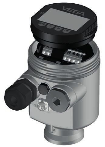
2 For your safety

                               2     For your safety
                               2.1    Authorised personnel
                               All operations described in this documentation must be carried out
                               only by trained, qualified personnel authorised by the plant operator.
                               During work on and with the device, the required personal protective
                               equipment must always be worn.

                               2.2    Appropriate use
                               The pluggable display and adjustment module is used for measured
                               value indication, adjustment and diagnoses with continuously meas-
                               uring sensors.
                               You can find detailed information about the area of application in
                               chapter " Product description".
                               Operational reliability is ensured only if the instrument is properly
                               used according to the specifications in the operating instructions
                               manual as well as possible supplementary instructions.

                               2.3    Warning about incorrect use
                               Inappropriate or incorrect use of this product can give rise to applica-
                               tion-specific hazards, e.g. vessel overfill through incorrect mounting
                               or adjustment. Damage to property and persons or environmental
                               contamination can result. Also, the protective characteristics of the
                               instrument can be impaired.

                               2.4    General safety instructions
                               This is a state-of-the-art instrument complying with all prevailing
                               regulations and directives. The instrument must only be operated in a
                               technically flawless and reliable condition. The operator is responsi-
                               ble for the trouble-free operation of the instrument. When measuring
                               aggressive or corrosive media that can cause a dangerous situation
                               if the instrument malfunctions, the operator has to implement suitable
                               measures to make sure the instrument is functioning properly.
                               During the entire duration of use, the user is obliged to determine the
                               compliance of the necessary occupational safety measures with the
                               current valid rules and regulations and also take note of new regula-
                               tions.
                               The safety instructions in this operating instructions manual, the na-
                               tional installation standards as well as the valid safety regulations and
                               accident prevention rules must be observed by the user.
                               For safety and warranty reasons, any invasive work on the device
                               beyond that described in the operating instructions manual may be
                               carried out only by personnel authorised by the manufacturer. Arbi-
36433-EN-210811

                               trary conversions or modifications are explicitly forbidden. For safety
                               reasons, only the accessory specified by the manufacturer must be
                               used.
                               To avoid any danger, the safety approval markings and safety tips on
                               the device must also be observed.

                  PLICSCOM •                                                                             5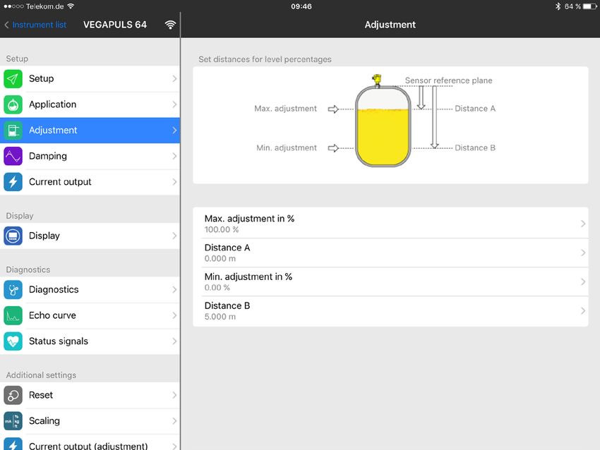
2 For your safety

                    2.5     EU conformity
                    The device fulfils the legal requirements of the applicable EU direc-
                    tives. By affixing the CE marking, we confirm the conformity of the
                    instrument with these directives.
                    The EU conformity declaration can be found on our homepage.

                    2.6     NAMUR recommendations
                    NAMUR is the automation technology user association in the process
                    industry in Germany. The published NAMUR recommendations are
                    accepted as the standard in field instrumentation.
                    The device fulfils the requirements of the following NAMUR recom-
                    mendations:
                    •   NE 21 – Electromagnetic compatibility of equipment
                    •   NE 53 – Compatibility of field devices and display/adjustment
                        components
                    For further information see www.namur.de.

                    2.7     Security concept, Bluetooth operation
                    Sensor adjustment via Bluetooth is based on a multi-stage security
                    concept.

                    Authentication
                    When starting Bluetooth communication, an authentication is carried
                    out between sensor and adjustment device by means of the sensor
                    PIN. The sensor PIN is part of the respective sensor and must be
                    entered in the adjustment device (smartphone/tablet). To increase
                    adjustment convenience, this PIN is stored in the adjustment device.
                    This process is secured via an algorithm acc. to standard SHA 256.

                    Protection against incorrect entries
                    In case of multiple incorrect PIN entries in the adjustment device,
                    further entries are possible only after a certain amount of time has
                    passed.

                    Encrypted Bluetooth communication
                    The sensor PIN as well as the sensor data are transmitted encrypted
                    between sensor and adjustment device according to Bluetooth
                    standard 4.0.

                    Modification of the default sensor PIN
                    Authentication by means of the sensor PIN is only possible after the
                    default sensor PIN " 0000" has been changed in the sensor by the
                    user.

                    2.8     Radio licenses
                                                                                            36433-EN-210811

                    The radio module used in the instrument for wireless Bluetooth com-
                    munication is approved for use in countries of the EU and EFTA. It
                    was tested by the manufacturer according to the latest edition of the
                    following standard:
                    •   EN 300 328 - Wideband transmission systems

6                                                                              PLICSCOM •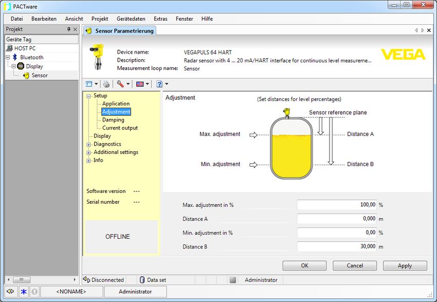
2 For your safety

                               The radio module used in the instrument for wireless Bluetooth com-
                               munication has also radio licenses for the the following countries
                               applied for by the manufacturer:
                               •   Canada - IC: 1931B-BL600
                               •   Morocco - AGREE PAR L’ANRT MAROC Numéro d’agrément:
                                   MR00028725ANRT2021 Date d’agrément: 17/05/2021
                               •   South Korea - R-R-VGG-PLICSCOM
                               •   USA - FCC ID: P14BL600

                               2.9    Environmental instructions
                               Protection of the environment is one of our most important duties.
                               That is why we have introduced an environment management system
                               with the goal of continuously improving company environmental pro-
                               tection. The environment management system is certified according
                               to DIN EN ISO 14001.
                               Please help us fulfil this obligation by observing the environmental
                               instructions in this manual:
                               •   Chapter " Packaging, transport and storage"
                               •   Chapter " Disposal"
36433-EN-210811

                  PLICSCOM •                                                                          7
3 Product description
3 Product description
3.1 Configuration
Scope of delivery The scope of delivery encompasses:
• Display and adjustment module
• Magnetic pen (with Bluetooth version)
• Documentation
–– This operating instructions manual
Note:
Optional instrument features are also described in this operating
instructions manual. The respective scope of delivery results from the
order specification.
Scope of this operating This operating instructions manual applies to the following hardware
instructions and software versions of the display and adjustment module with
Bluetooth:
• Hardware from 1.12.0
• Software from 1.14.0
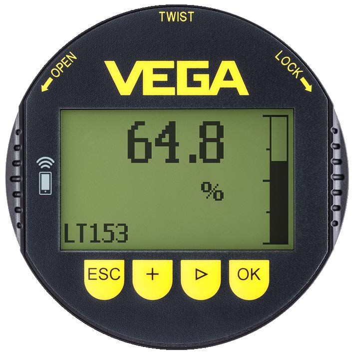
Instrument versions The indicating/adjustment module consists of a display with full dot
matrix as well as four keys for adjustment.
An LED background lighting is integrated in the display. It can be
switched off or on via the adjustment menu.
The instrument is optionally equipped with Bluetooth functionality.
This version allows wireless adjustment of the sensor via smartphone/
tablet or PC/notebook. Furthermore, the keys of this version can also
be operated with a magnetic pen right through the closed housing lid
with inspection window.
Type label The type label contains the most important data for identification and
use of the instrument:
1
7
2
6
3
5
4
Fig. 1: Layout of the type label (example)
1 Instrument type/Product code
2 Data matrix code for VEGA Tools app
36433-EN-210811
3 Serial number of the instrument
4 Field for approvals
5 Switch position for Bluetooth function
8 PLICSCOM •3 Product description
3.2 Principle of operation
Application area The pluggable display and adjustment module PLICSCOM is used for
measured value indication, adjustment and diagnosis for the following
VEGA instruments:
• VEGAPULS series 60
• VEGAFLEX series 60 and 80
• VEGASON series 60
• VEGACAL series 60
• PROTRAC series
• VEGABAR series 50, 60 and 80
• VEGADIF 65
• VEGADIS 61, 81
• VEGADIS 82 1)
Wireless connection The display and adjustment module PLICSCOM with integrated
Bluetooth functionality allows wireless connection to smartphones/
tablets or PCs/notebooks.
1
3
2
5
4
Fig. 2: Wireless connection to standard operating devices
1 Display and adjustment module
2 Sensor
3 Smartphone/Tablet
4 PC/Notebook
36433-EN-210811
Installation in the sensor The display and adjustment module is mounted into the respective
housing sensor housing.
1)
The operation of a display and adjustment module with integrated Bluetooth
function is not supported by VEGADIS 82.
PLICSCOM • 93 Product description
The electrical connection is carried out via spring contacts in the
sensor and contact surfaces in the display and adjustment module.
After mounting, the sensor and display and adjustment module are
splash-water protected even without housing lid.
Mounting in the external The external display and adjustment unit is another installation option.
display and adjustment
unit
Range of functions The range of functions of the display and adjustment module is deter-
mined by the sensor and depends on the respective software version
of the sensor.
Voltage supply Power is supplied directly via the respective sensor or the external
display and adjustment unit. An additional connection is not required.
The backlight is also powered by the sensor or the external display
and adjustment unit. Prerequisite for this is a supply voltage at a
certain level. The exact voltage specifications can be found in the
operating instructions manual of the respective sensor.
Heating
The optional heating requires its own operating voltage. You can find
further details in the supplementary instructions manual " Heating for
display and adjustment module".
3.3 Packaging, transport and storage
Packaging Your instrument was protected by packaging during transport. Its
capacity to handle normal loads during transport is assured by a test
based on ISO 4180.
The packaging consists of environment-friendly, recyclable card-
board. For special versions, PE foam or PE foil is also used. Dispose
of the packaging material via specialised recycling companies.
Transport Transport must be carried out in due consideration of the notes on the
transport packaging. Nonobservance of these instructions can cause
damage to the device.
Transport inspection The delivery must be checked for completeness and possible transit
damage immediately at receipt. Ascertained transit damage or con-
cealed defects must be appropriately dealt with.
Storage Up to the time of installation, the packages must be left closed and
stored according to the orientation and storage markings on the
outside.
Unless otherwise indicated, the packages must be stored only under
the following conditions:
• Not in the open
• Dry and dust free
36433-EN-210811
• Not exposed to corrosive media
• Protected against solar radiation
• Avoiding mechanical shock and vibration
10 PLICSCOM •3 Product description
Storage and transport • Storage and transport temperature see chapter " Supplement -
temperature Technical data - Ambient conditions"
• Relative humidity 20 … 85 %
36433-EN-210811
PLICSCOM • 114 Prepare setup
4 Prepare setup
4.1 Insert display and adjustment module
The display and adjustment module can be inserted into the sensor
and removed again at any time. You can choose any one of four differ-
ent positions - each displaced by 90°. It is not necessary to interrupt
the power supply.
Proceed as follows:
1. Unscrew the housing lid
2. Place the display and adjustment module on the electronics in the
desired position and turn it to the right until it snaps in.
3. Screw housing lid with inspection window tightly back on
Disassembly is carried out in reverse order.
The display and adjustment module is powered by the sensor, an ad-
ditional connection is not necessary.
Fig. 3: Installing the display and adjustment module in the electronics compart-
ment of the single chamber housing
36433-EN-210811
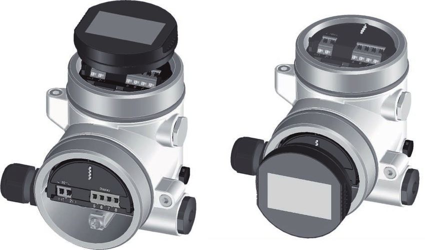
12 PLICSCOM •4 Prepare setup
1 2
Fig. 4: Installing the display and adjustment module in the double chamber
housing
1 In the electronics compartment
2 In the connection compartment
Note:
If you intend to retrofit the instrument with a display and adjustment
module for continuous measured value indication, a higher lid with an
inspection glass is required.
4.2 Adjustment system
1
2
Fig. 5: Display and adjustment elements
1 LC display
2 Adjustment keys
Key functions • [OK] key:
–– Move to the menu overview
–– Confirm selected menu
–– Edit parameter
–– Save value
• [->] key:
–– Change measured value presentation
36433-EN-210811
–– Select list entry
–– Select menu items
–– Select editing position
• [+] key:
PLICSCOM • 134 Prepare setup
–– Change value of the parameter
• [ESC] key:
–– Interrupt input
–– Jump to next higher menu
Operating system - Keys The instrument is operated via the four keys of the display and
direct adjustment module. The individual menu items are shown on the LC
display. You can find the function of the individual keys in the previous
illustration.
Adjustment system - keys With the Bluetooth version of the display and adjustment module you
via magnetic pen can also adjust the instrument with the magnetic pen. The pen oper-
ates the four keys of the display and adjustment module right through
the closed lid (with inspection window) of the sensor housing.
1
2
4 3
Fig. 6: Display and adjustment elements - with adjustment via magnetic pen
1 LC display
2 Magnetic pen
3 Adjustment keys
4 Lid with inspection window
Time functions When the [+] and [->] keys are pressed quickly, the edited value,
or the cursor, changes one value or position at a time. If the key is
pressed longer than 1 s, the value or position changes continuously.
When the [OK] and [ESC] keys are pressed simultaneously for more
than 5 s, the display returns to the main menu. The menu language is
then switched over to " English".
Approx. 60 minutes after the last pressing of a key, an automatic reset
to measured value indication is triggered. Any values not confirmed
with [OK] will not be saved.
36433-EN-210811
14 PLICSCOM •5 Parallel operation of display and adjustment modules
5 Parallel operation of display and
adjustment modules
Depending on the generation as well as hardware version (HW) and
software version (SW) of the respective sensor, parallel operation of
the display and adjustment modules in the sensor and in the external
display and adjustment unit is possible.
You can recognize the instrument generation by looking at the termi-
nals. The differences are described below:
5.1 Sensors of the older generations
With the following hardware and software versions of the sensor,
parallel operation of several display and adjustment modules is not
possible:
• HW < 2.0.0, SW < 3.99
On these instruments, the interfaces for the integrated display and
adjustment module and the external display and adjustment unit are
connected internally. The terminals are shown in the following graphic:
1
Display
I²C
1 2 5 6 7 8 2
Fig. 7: Interfaces for display and adjustment
1 Spring contacts for display and adjustment module
2 Terminals for external display and adjustment unit
5.2 Sensors of the newer generation
With the following hardware and software versions of the sensors,
parallel operation of several display and adjustment modules is pos-
sible:
• Radar sensors VEGAPULS 61, 62, 63, 65, 66, 67, SR68 and 68
with HW ≥ 2.0.0, SW ≥ 4.0.0 as well as VEGAPULS 64, 69
• Sensors with guided radar with HW ≥ 1.0.0, SW ≥ 1.1.0
• Pressure transmitter with HW ≥ 1.0.0, SW ≥ 1.1.0
On these instruments, the interfaces for the display and adjustment
module and the external display and adjustment unit are separate:
36433-EN-210811
PLICSCOM • 155 Parallel operation of display and adjustment modules
1
2
(+)1 2(-) 5 6 7 8
Fig. 8: Interfaces for display and adjustment
1 Spring contacts for display and adjustment module
2 Terminals for external display and adjustment unit
If the sensor is operated via the one display and adjustment module,
the message " Adjustment blocked" appears on the other one. Simul-
taneous adjustment is thus impossible.
Connection of more than one display and adjustment module on one
interface, or a total of more than two display and adjustment modules,
however, is not supported.
36433-EN-210811
16 PLICSCOM •6 Set up Bluetooth connection with smartphone/tablet
6 Set up Bluetooth connection with
smartphone/tablet
6.1 Preparations
System requirements Make sure that your smartphone/tablet meets the following system
requirements:
• Operating system: iOS 8 or newer
• Operating system: Android 5.1 or newer
• Bluetooth 4.0 LE or newer
Download the VEGA Tools app from the " Apple App Store", " Goog-
le Play Store" or " Baidu Store" to your smartphone or tablet.
Activate Bluetooth Make sure that the Bluetooth function of the display and adjustment
module is activated. For this, the switch on the bottom side must be
set to " On".
Factory setting is " On".
1
On
Off
Fig. 9: Activate Bluetooth
1 Switch
On = Bluetooth active
Off = Bluetooth not active
Change sensor PIN The security concept of Bluetooth operation absolutely requires that
the default setting of the sensor PIN be changed. This prevents unau-
thorized access to the sensor.
The default setting of the sensor PIN is " 0000". First of all you have
to change the sensor PIN in the adjustment menu of the respective
sensor, e.g. to " 1111".
After the sensor PIN has been changed, sensor adjustment can be
enabled again. For access (authentication) with Bluetooth, the PIN is
still effective.
36433-EN-210811
In the case of newer generation sensors, for example, this looks as
follows:
PLICSCOM • 176 Set up Bluetooth connection with smartphone/tablet
Information:
Bluetooth communication functions only if the actual sensor PIN dif-
fers from the default setting " 0000".
6.2 Connecting
Connecting Start the adjustment app and select the function "Setup". The smart-
phone/tablet searches automatically for Bluetooth-capable instru-
ments in the area.
The message " Searching …" is displayed.
All found instruments will be listed in the adjustment window. The
search is continued automatically.
Select the requested instrument in the device list.
The message " Connecting …" is displayed.
Authenticate For the first connection, the operating device and the sensor must
authenticate each other. After successful authentication, the next con-
nection functions without authentication.
For authentication, enter in the next menu window the 4-digit PIN
which is used to Lock/Unlock the sensor (sensor PIN).
Note:
If an incorrect sensor PIN is entered, the PIN can only be entered
again after a delay time. This time gets longer after each incorrect
entry.
Connected After connection, the sensor adjustment menu appears on the
respective operating device. The display of the display and adjust-
ment module shows the Bluetooth symbol and " connected". Sensor
adjustment via the keys of the display and adjustment module itself is
not possible in this mode.
Note:
With devices of the older generation, the display remains unchanged,
sensor adjustment via the keys of the display and adjustment module
is possible.
If the Bluetooth connection is interrupted, e.g. due to a too large
36433-EN-210811
distance between the two devices, this is displayed on the operating
device. The message disappears when the connection is restored.
18 PLICSCOM •6 Set up Bluetooth connection with smartphone/tablet
6.3 Sensor parameter adjustment
Enter parameters The sensor adjustment menu is divided into two halves:
On the left you'll find the navigation section with the menus " Setup", "
Display", " Diagnosis" and others.
The selected menu item, recognisable by the colour change, is dis-
played in the right half.
Fig. 10: Example of an app view - Setup measured values
Enter the requested parameters and confirm via the keyboard or the
editing field. The settings are then active in the sensor.
Close the app to terminate connection.
36433-EN-210811
PLICSCOM • 197 Set up Bluetooth connection with PC/notebook
7 Set up Bluetooth connection with PC/
notebook
7.1 Preparations
System requirements Make sure that your PC meets the following system requirements:
• Operating system Windows
• DTM Collection 03/2016 or higher
• USB 2.0 interface
• Bluetooth USB adapter
Activate Bluetooth USB Activate the Bluetooth USB adapter via the DTM. Sensors with
adapter Bluetooth-capable display and adjustment module are found and cre-
ated in the project tree.
Activate Bluetooth Make sure that the Bluetooth function of the display and adjustment
module is activated. For this, the switch on the bottom side must be
set to " On".
Factory setting is " On".
1
On
Off
Fig. 11: Activate Bluetooth
1 Switch
on Bluetooth active
off Bluetooth not active
Change sensor PIN The security concept of Bluetooth operation absolutely requires that
the default setting of the sensor PIN be changed. This prevents unau-
thorized access to the sensor.
The default setting of the sensor PIN is " 0000". First of all you have
to change the sensor PIN in the adjustment menu of the respective
sensor, e.g. to " 1111".
After the sensor PIN has been changed, sensor adjustment can be
36433-EN-210811
enabled again. For access (authentication) with Bluetooth, the PIN is
still effective.
In the case of newer generation sensors, for example, this looks as
follows:
20 PLICSCOM •7 Set up Bluetooth connection with PC/notebook
Information:
Bluetooth communication functions only if the actual sensor PIN dif-
fers from the default setting " 0000".
7.2 Connecting
Connecting Select the requested device for the online parameter adjustment in
the project tree.
Authenticate The window " Authentication" is displayed. For the first connection,
the operating device and the device must authenticate each other.
After successful authentication, the next connection functions without
authentication.
For authentication, enter the 4-digit PIN used to lock/unlock the
device (sensor PIN).
Note:
If an incorrect sensor PIN is entered, the PIN can only be entered
again after a delay time. This time gets longer after each incorrect
entry.
Connected After connection, the sensor DTM appears. With devices of the newer
generation, the display of the display and adjustment module shows
the Bluetooth symbol and " connected". Sensor adjustment via the
keys of the display and adjustment module itself is not possible in this
mode.
Note:
With devices of the older generation, the display remains unchanged,
sensor adjustment via the keys of the display and adjustment module
is possible.
If the connection is interrupted, e.g. due to a too large distance
between device and PC/notebook, the message " Communication
failure" is displayed. The message disappears when the connection
is restored.
7.3 Sensor parameter adjustment
36433-EN-210811
Prerequisites For parameter adjustment of the sensor via a Windows PC, the con-
figuration software PACTware and a suitable instrument driver (DTM)
according to FDT standard are required. The up-to-date PACTware
version as well as all available DTMs are compiled in a DTM Collec-
PLICSCOM • 217 Set up Bluetooth connection with PC/notebook
tion. The DTMs can also be integrated into other frame applications
according to FDT standard.
Fig. 12: Example of a DTM view - Setup, sensor adjustment
36433-EN-210811
22 PLICSCOM •8 Maintenance and fault rectification
8 Maintenance and fault rectification
8.1 Maintenance
Maintenance If the device is used properly, no special maintenance is required in
normal operation.
Cleaning The cleaning helps that the type label and markings on the instrument
are visible.
Take note of the following:
• Use only cleaning agents which do not corrode the housings, type
label and seals
• Use only cleaning methods corresponding to the housing protec-
tion rating
8.2 How to proceed if a repair is necessary
You can find an instrument return form as well as detailed information
about the procedure in the download area of our homepage. By doing
this you help us carry out the repair quickly and without having to call
back for needed information.
In case of repair, proceed as follows:
• Print and fill out one form per instrument
• Clean the instrument and pack it damage-proof
• Attach the completed form and, if need be, also a safety data
sheet outside on the packaging
• Ask the agency serving you to get the address for the return ship-
ment. You can find the agency on our homepage.
36433-EN-210811
PLICSCOM • 239 Dismount
9 Dismount
9.1 Dismounting steps
Warning:
Before dismounting, be aware of dangerous process conditions such
as e.g. pressure in the vessel or pipeline, high temperatures, cor-
rosive or toxic media etc.
Take note of chapters " Mounting" and " Connecting to voltage sup-
ply" and carry out the listed steps in reverse order.
9.2 Disposal
The instrument consists of materials which can be recycled by spe-
cialised recycling companies. We use recyclable materials and have
designed the electronics to be easily separable.
WEEE directive
The instrument does not fall in the scope of the EU WEEE directive.
Article 2 of this Directive exempts electrical and electronic equipment
from this requirement if it is part of another instrument that does not
fall in the scope of the Directive. These include stationary industrial
plants.
Pass the instrument directly on to a specialised recycling company
and do not use the municipal collecting points.
If you have no way to dispose of the old instrument properly, please
contact us concerning return and disposal.
36433-EN-210811
24 PLICSCOM •10 Supplement
10 Supplement
10.1 Technical data
General data
Weight approx. 150 g (0.33 lbs)
Display and adjustment module
Display element Display with backlight
Measured value indication
ƲƲ Number of digits 5
Adjustment elements
ƲƲ 4 keys [OK], [->], [+], [ESC]
ƲƲ Switch Bluetooth On/Off
Protection rating
ƲƲ unassembled IP20
ƲƲ Mounted in the housing without lid IP40
Materials
ƲƲ Housing ABS
ƲƲ Inspection window Polyester foil
Functional safety SIL non-reactive
Bluetooth interface
Bluetooth standard Bluetooth LE 4.1
Max. participants 1
Effective range typ. 2) 25 m (82 ft)
Ambient conditions
Ambient temperature -20 … +70 °C (-4 … +158 °F)
Storage and transport temperature -40 … +80 °C (-40 … +176 °F)
36433-EN-210811
2)
Depending on the local conditions
PLICSCOM • 2510 Supplement
10.2 Dimensions
45,1mm
(1.78")
ø 66,3mm
27,6mm
(1.09")
(2.61")
9,7mm
(0.38")
Fig. 13: Dimensions of display and adjustment module
36433-EN-210811
26 PLICSCOM •10 Supplement
10.3 Industrial property rights
VEGA product lines are global protected by industrial property rights. Further information see
www.vega.com.
VEGA Produktfamilien sind weltweit geschützt durch gewerbliche Schutzrechte.
Nähere Informationen unter www.vega.com.
Les lignes de produits VEGA sont globalement protégées par des droits de propriété intellec-
tuelle. Pour plus d'informations, on pourra se référer au site www.vega.com.
VEGA lineas de productos están protegidas por los derechos en el campo de la propiedad indus-
trial. Para mayor información revise la pagina web www.vega.com.
Линии продукции фирмы ВЕГА защищаются по всему миру правами на интеллектуальную
собственность. Дальнейшую информацию смотрите на сайте www.vega.com.
VEGA系列产品在全球享有知识产权保护。
进一步信息请参见网站< www.vega.com。
10.4 License information for Open Source Software
Hashfunction acc. to mbed TLS: Copyright (C) 2006-2015, ARM Limited, All Rights Reserved
SPDX-License-Identifier: Apache-2.0
Licensed under the Apache License, Version 2.0 (the "License"); you may not use this
file except in compliance with the License. You may obtain a copy of the License at
http://www.apache.org/licenses/LICENSE-2.0.
Unless required by applicable law or agreed to in writing, software distributed under the License is
distributed on an "AS IS" BASIS, WITHOUT WARRANTIES OR CONDITIONS OF ANY KIND, either
express or implied. See the License for the specific language governing permissions and limitations
under the License.
10.5 Trademark
All the brands as well as trade and company names used are property of their lawful proprietor/
originator.
36433-EN-210811
PLICSCOM • 27Printing date:
36433-EN-210811
All statements concerning scope of delivery, application, practical use and operat-
ing conditions of the sensors and processing systems correspond to the information
available at the time of printing.
Subject to change without prior notice
© VEGA Grieshaber KG, Schiltach/Germany 2021
VEGA Grieshaber KG
Am Hohenstein 113 Phone +49 7836 50-0
77761 Schiltach E-mail: info.de@vega.com
Germany www.vega.comYou can also read