READING DATA FROM A DIGITAL MULTIMETER USING A RASPBERRY PI
←
→
Page content transcription
If your browser does not render page correctly, please read the page content below
Bachelor's thesis (UAS)

Information Technology

Networking

2013

             Ranjam Alee

             READING DATA FROM A
             DIGITAL MULTIMETER USING A
             RASPBERRY PI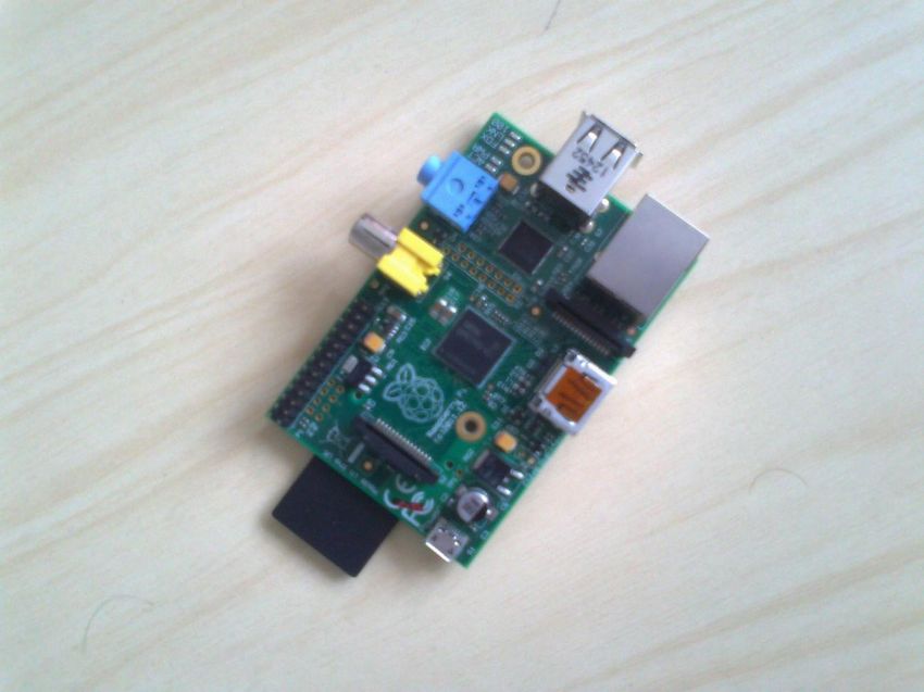
BACHELOR´S THESIS | ABSTRACT
TURKU UNIVERSITY OF APPLIED SCIENCES

Degree programme | Information technology

December 2013| 36

Instructor : Patric Granholm

Ranjam Alee

READING DATA FROM A DIGITAL
MULTIMETER USING A RASPBERRY
PI
The primary objective of this thesis was to read the data signal from a digital
multimeter on a Raspberry Pi. This thesis aims to analyze how a
communication process takes place between two devices.

This thesis was conducted using a Raspberry Pi and a Fluke digital multimeter.
The digital multimeter was connected with the Raspberry Pi using an USB-
Serial cable that comes with the multimeter. To access the data from the
multimeter, the Python programming language was used. The data obtained
using the Python program in a digital method was also tested with an analog
method simultaneously. One of the goals of this thesis was also to understand
the communication protocol that is used by the two devices for talking to each
other.

On the basis of the tests and the results obtained, it was concluded that the
data thus received using the python program was genuine. Therefore, reading
data from the digital multimeter in Raspberry Pi was successfully carried out.

KEYWORDS:

(Ras pberry-Pi, digit al multimeter, Python)

FOREWORD

I would like to thank and express my sincere gratitude to my supervisor, Mr.
Patric Granholm for supporting me with everything throughout this thesis. His
advice, guidance and motivation have been really helpful to me.

I thank and offer my heartily appreciation to my teacher and language instructor
Mrs. Poppy Skarli for her guidance and support throughout my studies.

In addition, I also want to thank all my teachers (Balsam, Hazem al-Bermanei,
Osseo and Visa Slotted) whose knowledge and advice have been a great help
for me during my studies.
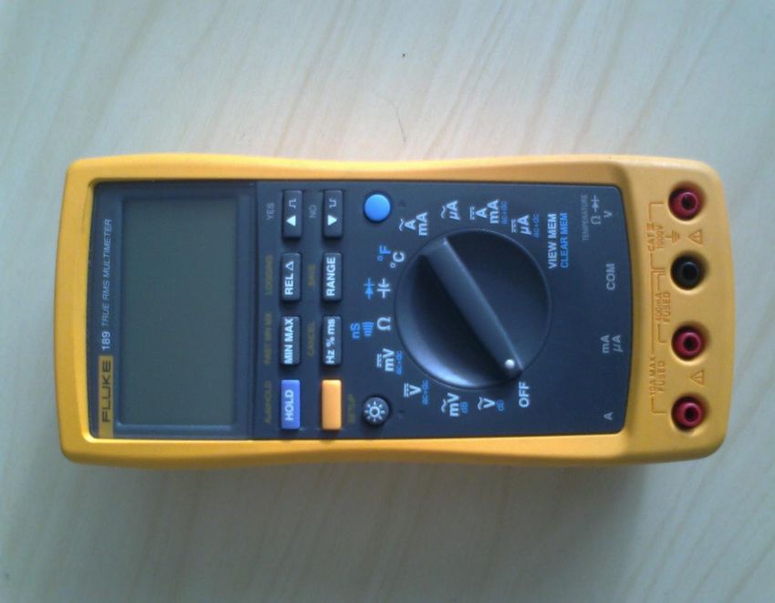
TABLE OF CONTENTS

LIST OF ABBREVIATIONS (OR) SYMBOLS                         5
1 INTRODUCTION                                             7
2 RASPBERRY PI                                             8
2.1 History of Raspberry Pi                               8
2.2 Hardware and Specification                            9
3 FLUKE DIGITAL MULTIMETER                                11
4 DAT A COMMUNICATION                                     12
4.1 Synchronous Data Transmission                         14
4.2 Asynchronous Data Transmission                        14
4.3 Serial Ports                                          17
4.3.1 TTY driver                                          18
5 METHODOLOGY                                             20
5.1 Setting up Raspberry Pi                               20
5.2 USB-Serial Interface                                  21
5.3 Connecting Digital multimeter to Raspberry Pi         23
5.4 Programming                                           26
5.4.1 Pyserial                                            27
5.4.2 Program Overview                                    28
6 TESTING AND RESULTS                                     29
7 CONCLUSION                                              32
7.1 Future Work                                           32
REFERENCES                                                33

APPENDIX

PICTURES

Picture 1. A Raspberry Pi                                 8

Picture 2. A digital multimeter                           12

Picture 3. The multimeter and Raspberry Pi's connection   23

Picture 4. Testing                                        30
FIGURES

Figure 1. Raspberry Pi‟s hardware                           9

Figure 2. Types of communication channels                   13

Figure 3. Data flow of synchronous transmission             14

Figure 4. UART                                              15

Figure 5. Asynchronous frame                                16

Figure 6. TTY driver                                        19

Figure 7. lsusb screenshot                                  21

Figure 8. Data flow                                         24

Figure 9. lsmode screenshot                                 24

Figure 10. Dmesg screenshot                                 25

Figure 11. ls /dev screenshot                               26

Figure 12. Program flowchart                                28

Figure 13. Logged data                                      32

TABLES

Table 1. Raspberry Pi‟s specifications                      10

LIST OF ABBREVIATIONS (OR) SYMBOLS

Raspberry Pi                 Raspberry Pi

DMM                          Digital Multimeter

RCA                          Radio Cooperation of America

SD                           Secure Digital

SDIO                         Secure Digital Input Output

MMC                          Multimedia Card

GPIO                         General Purpose Input Output
HDMI     High Definition Multimedia Interface

USB      Universal Serial Bus

CPU      Central Processing Unit

GPU      Graphics Processing Unit

SoC      System on Chip

SDRAM    Synchronous Dynamic Random Access Memory

UART     Universal Asynchronous Receiver and Transmitter

I2C      Inter-Integrated Circuit

SPI      Serial Peripheral Interface

NTSC     National Television System Committee

PAL      Phase Alternating Line

DC       Direct Current

Pty      Pseudo teletypewriter

EEPROM   Electrically Erasable Programmable Read Only Memory

I/O      Input Output

MCU      Microcontroller Unit

FPGA     Field-Programmable Gate Array

VCP      Virtual Com Port

LED      Light Emitting Diode

BSD      Berkeley Software Distribution

POSIX    Portable Operating System Interface

API      Application Programming Interface

CR/LF    Carriage return/ Line feed
1 INTRODUCTION

In today‟s world, where computers are becoming more powerful and advanced,
a Raspberry Pi looks like a tiny open circuit board. Since its introduction in the
computer field, Raspberry Pi is gradually becoming popular among the
students. The Raspberry Pi was developed with an intention that every student
can have their own affordable computer. It connects into a TV and a keyboard,
and thus a cheap computer is ready. This cheap tiny computer has the ability to
perform many tasks such as word processing, playing games, programming
and so on. There are many projects that can be performed using this single
board computer.

This thesis shows one of the experiments that can be carried out using a
Raspberry Pi and a digital multimeter. Although this kind of experiments have
been carried out on Linux and Windows systems, this thesis provides more
information on what goes behind the communication between the two electronic
instruments. A digital multimeter was chosen for this thesis because it is one of
the commonly found useful testing devices in laboratories. The thesis focuses
on how the test readings from the digital multimeter can be read via Raspberry
Pi and possibly be logged in some text files . This thesis includes some
information about a Raspberry Pi, Fluke multimeter along with the RS-232
communication protocol. This thesis does not include information on how to
write a device driver.

This thesis study starts with some introduction of Raspberry Pi and fluke digital
multimeter. It also focuses on what is a serial communication protocol. Further,
it deals with development of program, testing of the program and finally the
conclusion of the thesis.
2 RASPBERRY PI

A Raspberry Pi is a small, credit-card sized micro computer developed by
Raspberry Pi Foundation, UK. This single boarded computer was developed
with aim of teaching the basics of computer science and programming to school
students all around the world. Although a microcontroller, like Arduino, is trendy
for prototyping projects, a Raspberry Pi is quite different from the popular
microcontroller. Actually, it is more like a computer than an Arduino.

            Picture 1. A Raspberry Pi

2.1 History of Raspberry Pi
The history of development of Raspberry Pi dates back to 2006. Realizing the
decline of interests in computer sciences, some scientists (Eben Upton, Jack
Lang and Alan Mycroft) from the Computer Laboratory in University of
Cambridge decided to develop something cheap and small which would help
students gain computer skills. Although many prototypes of their concept of
small and cheap computers were designed from 2006 to 2008, it was only in
2012 when they finally created a credit card-sized, low-priced, tiny computer
called Raspberry Pi. (Raspberry Pi Foundation 2013)
2.2 Hardware and specifications
Raspberry Pi is found in two versions. Model A and Model B. Although Model A
is cheaper than Model B, there are some other differences in these two versions
of Raspberry Pi. Model A has a 256MB memory, comes with a single USB port
and does not have any Ethernet port whereas model B has a 512MB memory, 2
USB ports, and an Ethernet port as well.
Figure1. Raspberry Pi‟s hardware (Raspberry Pi 2013)
A Raspberry Pi consists of many important hardware parts with some useful
functions. The main part of a Raspberry Pi is its Processor. Every Raspberry Pi
has a Broadcom BCM2835 chip which embodies an ARM1176JZF-S CPU core.The chip has a clock speed of 700MHz and it is a 32-bit System. A Raspberry
Pi has a SD card slot for a SD card which acts as the storage media for it.
Everything including the operating system and other files are stored in the SD
card. The HDMI port is used as audio and video output. A HDMI to DVI (Digital
Visual Interface) converter can be used to convert the HDMI signals to DVI
which is normally used by monitors. The Raspberry Pi has the Status LED
which provides the visual information. For instance, the first green light (marked
as ACT on Raspberry Pi board) indicates that the SD card is accessed, the
second green LED (marked as FDX) indicates the full duplex network and the
third green LED (marked as LNK) indicates the link activity. Similarly, the red
light (marked as PWR) announces the power of 3.3v and the yellow LED
(marked as 100) hints the 100Mbps network connection. The 5v DC through a
micro USB powers up the Raspberry Pi. This device also has a RCA composite
video connector for video output as well as a 3.5mm stereo jack for audio
output. The Raspberry Pi has 26 GPIO pins which help to connect to low level
peripherals and expansion boards. (Richardson & Wallace 2012)
Raspberry Pi’s specifications
Table1. Raspberry Pi‟s specifications (Raspberry Pi Model A & Model B
Comparison 2013)
Technical Features Model A Model B
SoC (System on Chip) Broadcom BCM2835
CPU 700 MHz Low power ARM1176JZ-F
GPU Dual Core VideoCore IV multimedia Co-processor
Memory 256MB SDRAM 512MB SDRAM
USB 2.0 1 2
Video Out Composite RCA(PAL and NTSC), HDMI
Audio Out 3.5mm jack, HDMI
Storage SD/MMC/SDIO card slot
Network No port RJ45 Ethernet
2
Peripheral Connectors 8xGPIO, UART, I C bus, SPI bus
Power Source 5Volt DC via MicroUSB or GIOP headersThe Raspberry Pi used for this thesis study uses Raspbian Wheezy as an operating system. Raspbian is a Debian based free OS ( operating system) for Raspberry Pi. 3 FLUKE DIGITAL MULTIMETER The digital multimeter used for this thesis was Fluke 189 true RMS. There is a difference between a true RMS multimeters and non-true RMS or averaging multimeters. A non-true RMS multimeter measures the average amount of current or voltage whereas a true RMS multimeters uses root mean square to accurately measure AC voltage or current. This Fluke 189 true RMS multimeter possesses built-in data logging capabilities. This special multimeter can monitor temperature also along with many other electrical functions like measuring voltage, continuity, capacitance, resistances, etc. It is one of the most accurate and dependabale digital multimeter. It comes with a USB interface which is a kind of RS-232C interface that can be connected to a PC for data acquisition.
Picture2. A digital multimeter

4 DATA COMMUNICATION

The process of transferring data or information between two devices connected
with a communicating media is called data communication. A communicating
media is a pathway or a channel over which the data or information is
transmitted or received. This media can be a physical wire, radio signals or
lasers. Basically, there are two kinds of channels for communication. The
simplest communication channel is one way channel, also, known as simplex.
In this type of communication channel, data or signals are transmitted only in
one direction. For example, a TV station or a radio station is a kind of simplex
channel. The other type of communication channel is a two-way communication
channel. Further, it has got two forms, namely, full-duplex and half duplex. Full
duplex is a form of two way communication where data are transmitted
simultaneously in both directions, for instance, mobile phones, landline phones,
etc. Whereas, in half duplex, data can be transmitted in both directions but not
at the same time, for example, a walkie-talkie.

            Figure 2. Types of communication channel

In the computer world, data communication mainly takes place in two ways:

            -   Parallel communication: It is one of the ways of communication
                where large blocks of data are transmitted at a time.
            -   Serial Communication: It is the way of communication where
                data are transmitted a bit at a time.

There are two modes of serial data transmission:

            -   Synchronous data transmission, and
            -   Asynchronous data transmission
4.1 Synchronous data transmission
Synchronous data transmission is the continuous and steady transfer of data.
This mode of transmission uses clock signals to synchronize the data transfer.
Since the synchronous mode is steady or consistent, it is used for transferring
long streams of data. Like asynchronous, this mode does not use any start bit
or stop bits which make it faster in data transfer. Due to the higher probability of
clocks being out of sync, this might result in more data loss or errors. (pSeries
and AIX Information Center 2013)
Figure 3. Data flow of synchronous transmission
When the receiver receives the syn characters, it becomes ready to
synchronize with the transmitter. As the synchronization betwee n transmitter
and receiver take place, now the synchronous data transmission process
begins.
4.2 Asynchronous data transmission
The main part of any electronic device is its processor. A processor has a chip
called UART (Universal Asynchronous Receiver and Transmitter) in it. This
microchip or UART is responsible for controlling serial communication between
a computer and serial devices. Basically, this UART prepares the computer with
talking environment to its connected serial devices. UART converts received
data bytes from a computer or a device and sends out bit streams for
transmission. These bit streams are some sets of 0s and 1s. This process ofsending a bit of data at a time is called serial communication. Unlike parallel
ports, serial ports use a single physical cable for the data transmission.
Figure 4.UART
The asynchronous transmission mode is the process of data transfer where
transmission is not synchronized by clock signals. Unlike synchronous
transmission, asynchronous is rather periodical. In other words, the data are not
transmitted continously. The data frames are bounded by a start bit and stop
bits. Although RS232 ports are considered as asynchronous, they still possess
an external clock and they are not used so often.Figure 5. Asynchronous frame There are a number of parameters that should be preagreed upon between the communicating devices in order to establish a good communication. These include: Baud rate The baud rate is symbols per second. Therefore, it is also known as symbol rate. The symbol rate can also be described as the number of times a signal changes its states. The Baud rate can be as low as 110 baud to as high as 921600. For example: 2400, 4800, 9600, 19200, etc are some of the standard baud rates. Data bits Data bits are the number of bits sent in a single frame. Data bits could range from 5 bits to 8 or 9 bits. The old system used 5 or 6 data bits. However, most of the applications today use 8 data bits. Data bits follow the start bit. Parity The parity bit is the extra bit that is added after the data bits for error checking. It is a simple bit that informs the receiver that it has received the accurate bit of
data. For a RS-232, it can be considered as an optional parameter. Parity can
be even, odd, or none.
Stop bit
The stop bit can be a bit or 2-bit long. Infact, it can be understood as a stop
period. The stop bit or bits indicate the end of the data bits. Start bits and stop
bits are used in asynchronous communication as timers.
To establish a communication between two devices, the number of data bits,
parity check (odd, even or none), baud rate and stop bits should be agreed prior
to communication. Otherwise, the signals might become corrupt or no
communication takes place. (Bies 2013)
Flow control
As the name suggests, it is used to control the flow of data. When two devices
are communicating with each other, the data processing of one device might be
less compared to the other. So, to establish a handshaking environment, data
flow controls are used. Flowcontrol is of two types:
Hardware flowcontrol
o RTS/CTS (request to send/clear to send) hardware
o DTR/DSR (data terminal ready/data set ready)
Software flowcontrol
o XON/XOFF
4.3 Serial ports
Serial ports are the physical interfaces used in computers to transmit and
receive data stream, one bit at a time. In earlier computers, serial ports were the
important external connectors to other peripherals. Although serial ports arebecoming less common in today‟s computer, they need serial ports for USB converters to connect to RS-232 devices. Any application cannot talk directly to USB-Serial cable. There has to be some kind of device driver (either provided by the operating system or installed by the user) for the communication. A device driver has a special part in a Linux kernel. These drivers enable a certain hardware piece to talk or to react to applications. Each device driver varies from another as they have to perform tasks according to the type of device/hardware they are dealing with. 4.3.1 TTY drivers TTY is an acronym for older teletypewriter. Today TTY is also associated with any serial port kind of device. Serial ports, USB to serial converters, are some of the TTY devices. In Linux, the TTY driver core lies just below char (short form for character) drivers level. The TTY driver core controls the data flow and data format across TTY devices. The TTY line discipline drivers in the driver help to control data flow.
Figure 6.TTY driver

When the TTY core receives data from the user space, it sends data to the TTY
line discipline. The line discipline driver then sends the data to TTY driver where
data conversion takes place. The data are converted to the particular format
that is understood by the TTY device. In a similar manner, the data from the
TTY device is transferred to the TTY driver and to the line discipline and
eventually reaches to user. The TTY driver can sometimes talk to TTY core
straightaway and vice versa. However, the TTY driver does not have any power
to talk to the line discipline directly. The TTY line discipline does the formatting
of the information from the TTY devices or from the user space in a certain
format, whereas the TTY driver converts the information to a certain format for
hardware or TTY devices and receives information from the TTY devices. TTY
drivers are of 3 types. They are serial port, PTY and console. (Corbet, Rubini &
Kroah-Hartman 2005)

5 METHODOLOGY

5.1 Setting up a Raspberry Pi

Requirements:

            1. An empty SD card ( minimum size of 4Gb)
            2. A HDMI to DVI converter to connect Raspberry Pi to a Monitor
            3. An USB Keyboard
            4. A micro USB power adapter
            5. An USB mouse(optional)

Preparing SD card to write the OS for the Raspberry Pi:

            1. Download recommended OS(Raspbian).
            2. Unzip the downloaded file / extract it. A file with .img extension
                can be seen.
            3. Download Win32DiskImager (or any software‟s like this) from
                http://sourceforge.net/projects/win32diskimager/.
            4. Unzip/extract the file.
            5. Insert the SD card into PC and Run the Win32diskimager
                software. Select the extracted .img image file and the drive
                where the image has to be written. Then click Write button.

First time booting of Raspberry Pi

            1. After the SD card is ready, insert it into Raspberry Pi, connect a
                moniter and an usb keyboard. Now, plug the power adapter.
                The LEDs start flashing. The Raspberry Pi starts to boot for the
                first time and eventually, a Raspi-config window pops up.
2. Change the required settings like expand_rootfs,
configure_keyboard, change_pass, etc.
3. After all the configuration made, finally select „Finish‟ to reboot
the Raspberry Pi.
4. After the reboot, Raspberry Pi promts to a raspberrypi login:
5. Enter the default login „pi‟ and the default password „raspberry‟
and press enter.
6. Finally, type startx to start the Raspbian desktop.
(Raspberry Pi 2013)
5.2 USB-Serial interface
When the digital multimeter is connected to the Raspberry Pi, the kernel detects
the type of the USB used by the multimeter. The connection between the
Raspberry Pi and the multimeter is done with a USB-Serial interface. This
interface has an integrated chip which converts the USB codes or signals to
serial or RS-232 data.
Figure 7.lsusb screenshot
After plugging the USB cable to Raspberry Pi, the ‟lsusb‟ command shows the
connector is a FT232 USB-Serial (UART) interface. The FT232 USB-Serial(UART) IC interface possesses some features as described by FTDI Company.
(Future Technology Devices International Limited 2010)
Single chip USB to asynchronous serial data transfer interface.
Whole USB protocol handled on the chip. USB specific firmware
programming not needed.
Fully integrated 1024 bit EEPROM storing device descriptors and CBUS
I/O configuration.
Fully integrated USB termination resistors.
Fully integrated clock generation with no external crystal required plus
optional clock output selection enabling a glue-less interface to external
MCU or FPGA.
Transfer rates of data ranging from 300 baud to 3 Mbaud (RS232,
RS422, and RS485) at TTL levels.
128 byte receive buffer and 256 byte transmit buffer utilizing buffer
smoothing technology to allow for high data throughput.
FTDI‟s royalty-free Virtual Com Port (VCP) and Direct (D2XX) drivers
eliminate the requirement for USB driver development in most cases.
Unique USB FTDIChip-ID™ feature.
CBUS I/O pins can be configured.
Transmit and receive LED drive signals.
UART interface support for 7 or 8 data bits, 1 or 2 stop bits and odd /
even / mark / space / no parity
FIFO receive and transmit buffers for high data throughput.
Device supplied pre-programmed with unique USB serial number.
Integrated +3.3V level converter for USB I/O.5.3 Connecting the digital multimeter to the Raspberry Pi
Picture3. The multimeter and Raspberry Pi‟s connection
For a successful communication between any two devices, there has to be a
medium that helps in a good communication. A Fluke digital multimeter comes
with a USB-Serial interface as data transmission medium. Therefore , the
communication process between a Raspberry Pi and the multimeter takes place
using the USB-Serial interface. The communication between these two devices
does not occur just by connecting them together. There has to be something
that performs the intermediary job. Pyserial is a module for Python, which helps
to interface between the user and the driver. For the communication to occur, a
user has to send a command requesting the data from the digital multimeter. In
response to this request, the multimeter sends the information that it possesses
to the user. Actually, Pyserial sits between the user space and the USB toUART driver and helps to access the serial port. The picture3 below shows how
the data flow between these devices takes place.
Figure 8. Data flow
The Raspbian kernel provides the device driving part automatically. This can be
examined by listing the modules loaded by the kernel. As the screenshot
indicates, the ftdi_sio and usbserial module are already being loaded by the
kernel.
Figure 9.lsmod screenshotFigure 10.dmesg screenshot The command ”dmesg” enables a user to observe various kernel messages. The figure above states that usbcore has registered an interface driver called ftdi_sio. The kernel has detected a FT232RL which is a USB to serial UART interface. Apart from this, the screenshot also informs that the USB serial device was recognized and is now attached to a device named ”ttyUSB0”. This ”ttyUSB0” can now be used as a normal serial port. The ”ttyUSB0” device name can be found in the ”/dev” directory.
Figure 11.ls /dev screenshot

5.4 Python Programming Language

The Python programming language was adopted to write a program for this
thesis study. Although the program could be written in other programming
languages such as C or C++, Python was chosen for this thesis as it is easy to
write and read. Also, the program written in Python can be executed instantly
without compiling the program.

Python is an open source high level programming language. It is created for the
ease of programmers so that they can depict their programming image in simple
and minimum words. Since the Python programming language does not need to
be compiled before running it as is done in C, C++ or Java, it is also called the
interpreted language. In other words, a script or any program written in Python
can be run directly. Python also saves time for the programmers as data types
do not have to be defined like in other programming languages. (Hughes 2013)
The operating system of Raspberry Pi, Raspbian already contains the Python
as its default programming language and IDLE 3. IDLE is a Raspberry Pi‟s
version of IDE (integrated development environment).
More information can be found from the official website of Python, http.
5.4.1 Pyserial
This module encapsulates the access for the serial port. It provides backend for
Python running on Windows, Linux, BSD (possibly any POSIX compliant
system), Jython and IronPython (.NET and Mono). The module named “serial”
automatically selects the appropriate backend (Liechti 2013).
Some of the Pyserial‟s features are:
The Pyserial files are written in absolute Python language.
Pyserial supports different values for serial port parameters (stop bits,
byte size, parity and flow controls).
Python properties provide access to the serial port settings.
Python‟s input/output library can be adapted with Pyserial.
5.4.2 Program OverviewFlowchart
Figure 12. Program Flowchart
The figure above shows a very basic flowchart for a simple Python script for
reading data from a multimeter. As mentioned earlier, the digital multimeter and
the Raspberry Pi should have the same parameters setting. Therefore, the baud
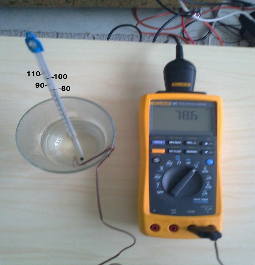
rate used for port ‟/dev/ttyUSB0‟ is 9600 bits per second, the byte size is 8 bits,the parity is none and the stop bit is one. The data can be received from digital multimeter only when it is triggered with a query command. 6 TESTING AND RESULTS When the Python script was executed, the multimeter would send some value to the Raspberry Pi. The data received from the multimeter had to be tested if the value was genuine. Therefore, the digital data from the multimeter was tested along with an analog device also. The testing was held taking some ice in a glass. A thermometer (alcohol) and the thermocouple of the multimeter were dipped into the ice. After the temperature readings in both instruments (thermometer and digital multimeter) were around 0 degree Celsius, the Python script was executed. As the Python program is running and logging data, some boiling water was poured in the glass. Due to the high temperature, the readings in both instrument started rising. Since the alcohol thermometer is an analog device, the alcohol level rises slowly in comparison to the digital multimeter. The testing could be done with other measurements like resistance, voltage, and other functions of the multimeter.
Picture 4. Test setup

Analyzing the readings from both the thermometer and the logged data from the
multimeter, the highest temperature of the water was found to be around 78.6
degrees Celsius.
Figure 13.Logged data
7 CONCLUSION
The primary goal of this thesis study was to read data from a digital multimeter
in a Raspberry Pi. To achieve this goal, a Python script was written. The script
was executed and data was accessed from the multimeter and logged in a file.
The digital data received using the program was also tested along with an
analog device. The data from both the device was found to be nearly similar
which proves that the correct data was read from the multimeter.
In conclusion, it can be stated that the data from the digital multimeter was
successfully read in a Raspberry Pi and the goal was achieved. As mentioned
in the introduction, this kind of project has been done in Windows and Linux, yet
there can be some more improvements made in this kind of project in the future
which are described in the next section.
7.1 Future Work
The following improvements can be implemented to improve this project.
The GUI version of this project can be developed with more user
friendly functions.
The data logged could be portrayed in graphs and chart which could
provide easy display of the logged data.REFERENCES Bies, L. 2013. RS232 Specifications and standard. Available at http://www.lammertbies.nl/comm/info/RS-232_specs.html. [Accessed 23 August 2013] Corbet, J., Rubini, A. & Kroah-Hartman, G. 2005. Linux Device Drivers., 3rd edition. Available also at http://lwn.net/Kernel/LDD3/. [Accessed 13 August 2013] FTDI - Wikipedia, the free encyclopedia 2013. Available at http://en.wikipedia.org/wiki/FTDI. [Accessed 24 September 2013] Future Technology Devices International Limited 2010.Available from http://www.ftdichip.com/Support/Documents/DataSheets/ICs/DS_FT232R.pdf . [Accessed 25 October 2013] Future Technology Devices International Ltd, 2012. Available at http://www.ftdichip.com/Products/ICs/FT232R.htm. [Accessed 24 September 2013] Huges, J M. 2010. Real World Instrumentation with Python. 1 st ed. United States of America: O‟Reilly Media Liechti, C. 2013. Welcome to pySerial‟s documentation. Available from http://pyserial.sourceforge.net/. [Accessed 2 September 2013] pSeries and AIX Information Center 2013. Available at http://publib.boulder.ibm.com/infocenter/pseries/v5r3/index.jsp?topic=/com.ibm. aix.commadmn/doc/commadmndita/asynch_params_startbits.htm. [Accessed 24th August 2013] Python (programming language) – Wikipedia, the free encyclopedia 2013. Available at http://en.wikipedia.org/wiki/Python_(programming_language). [Accessed 20 October 2013] Raspberry Pi Model A & Model B Comparison 2013. Available at http://downloads.element14.com/raspberryPi1.html. [Accessed 20 August 2013]
Richardson, M. & Wallace, S. 2012. Getting Started with Raspberry Pi. 1 st ed.
United States: Maker Media Inc.

The Raspberry Pi Foundation 2013. Available at http://www.raspberrypi.org/wp-
content/uploads/2012/04/quick-start-guide-v2_1.pdf   [Accessed     16   October
2013]

The     Raspberry     Pi     Foundation,     UK      2013.       Available   at
http://www.raspberrypi.org/about [Accessed 10 July 2013]
APPENDIX

Raspbian download:

http://www.raspberrypi.org/downloads

Pyserial download:

https://pypi.python.org/pypi/pyserial

Python Script:
import serial

import time

from time import gmtime, strftime

import struct

#serial port settings

dmm = serial.Serial(

port='/dev/ttyUSB0',

baudrate=9600,

bytesize=8,

parity=serial.PARITY_NONE,

stopbits=serial.STOPBITS_ONE,

   )

#handling exceptions

try:

dmm.open()

except Exception, e:
print "problem faced while openning the port : " +str(e)

exit()

print "Fluke 189 Digital Multimeter"
print "-------------------------------------------------------"
dmm.isOpen()

file = open("/home/pi/Ramzan_project/py_Serial/dmmLogFile.txt", "a")

while True:

dmm.write('QM\r')

dmm.flushInput()

data = dmm.read(14)

if data == '':

dmm.close()

else:

print data

time.sleep(1)

        print >>file,data,' -> ',strftime("%d %b %Y,%H:%M:%S")
file.flush()

file.close()
You can also read