RIM INSTRUCTION MANUAL - Warning
←
→
Page content transcription
If your browser does not render page correctly, please read the page content below
VERSION 2 (2017.03)

Multi-piece Rims for Industrial and Construction Vehicles

RIM INSTRUCTION MANUAL
          Warning
  In order to handle rims safely, correctly, and reliably, work
  supervisors and workers involved in handling rims must
  comply with the following:

    Only begin work after carefully reading and understanding
    this Rim Instruction Manual. Failure to follow these
    instructions and safety precautions can be extremely
    hazardous and result in SERIOUS INJURY or DEATH to the
    tire changer or bystanders.

    Keep this manual in a designated place where it is easily
    accessible. Maintain this manual for future use and review
    it whenever necessary.

    If there are any questions or clarifications required
    concerning the contents of this manual, please contact
    your distributor.

    When transferring rims to someone else, be sure to give
    them this manual.

             TOPY INDUSTRIES, LIMITED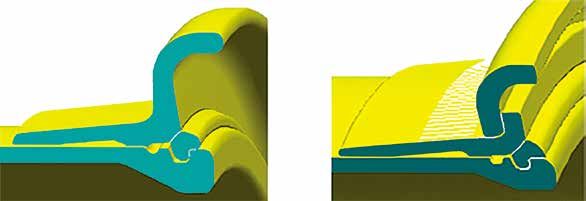
Introduction

           N This Rim Instruction Manual concerns TOPY multi-piece rims for industrial
             and construction vehicles. It contains detailed information regarding their
             construction, specifications and handling to ensure the safe use of these
             products. Failure to follow these instructions and safety precautions can be
             extremely hazardous and result in SERIOUS INJURY or DEATH to the tyre
             changer or bystanders.

           N Servicing of tyres and rims is very dangerous. This manual sets out
             important safety points and gives step-by-step explanations of the tasks
             involved in handling TOPY multi-piece rims.

           N Read Safety Points in this manual and be sure that you fully understand
             them before starting tyre and rim servicing.

           N When servicing tyres and rims, please refer to the following documents in
             addition to this manual:
                OSHA (U.S. Occupational Safety and Health Administration), Code of Federal
                Regulations 29 CFR Part 1910.177, “Servicing multi-piece and single-piece rim
                wheels”.
                MSHA (Mine Safety and Health Adiminstration) Introduction guide series IG60
                SAE (Society of Automotive Engineers) J1337 Off-Road Rim Maintenance
                Procedures and Service Precautions.
                RMA (U.S. Rubber Manufacturers Association) “CARE AND SERVICE OF OFF-
                THE-HIGHWAY TYRES”
                RMA (U.S. Rubber Manufacturers Association) “TYRE INFORMATION SERVICE
                BULLETIN”
                “Tyre and Rim Handling Manual”, published by tyre manufacturer.
                “Work Manual”, published by vehicle manufacturer.

           N In this manual, the word “rim” is used as a general term which includes
             wheels with discs.

           N Copying this manual for purposes other than ownership transfer is strictly
             forbidden.

1   (2008.08)                                                                           (2017.03)   1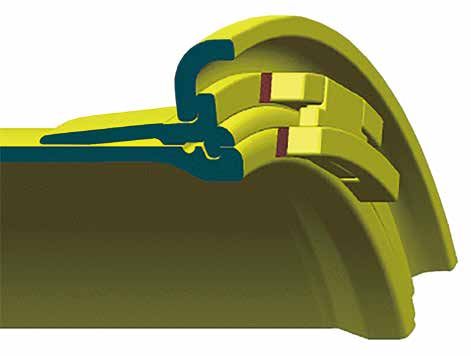
Contents

           1. Safety precautions ..................................................................................... 3
           2. General safety rules for rim handling........................................................ 3
           3. Important warnings ................................................................................... 4
                3.1 Precautions for prevention of "explosive separation of rim components" ...............                                             4
                3.2 Precautions for reduction or prevention of injury, death or damage from explosive

                     separation ....................................................................................................................   5
                3.3 General precautions .....................................................................................................          6
           4. Definitions of rim components .................................................................. 7
                4.1 Names and size specifications of rim components ....................................................                               7
                4.2 Designations of each rim component .........................................................................                       8
           5. Markings .................................................................................................... 9
                5.1 Location of markings ...................................................................................................           9
                5.2 Composition of markings .......................................................................................... 10
                5.3 Rim component specifications .................................................................................. 11

           6. Matching charts ....................................................................................... 14
           7. Examples of potentially hazardous matches .......................................... 18

           8. Procedures for servicing tyres and TOPY rims ...................................... 25
                8.1 How to demount tyre from TOPY 3-piece rim ........................................................... 26
                8.2 How to mount tyre onto TOPY 3-piece rim ............................................................... 31
                8.3 How to demount tyre from TOPY 5-piece rim ........................................................... 37
                8.4 How to mount tyre onto TOPY 5-piece rim ............................................................... 44
                8.5 Check point of servicing tyres and rims when rim remains installed on vehicle .... 53

           9. Maintenance............................................................................................. 55
                9.1 Regular inspection check points ............................................................................... 56
                9.2 Inspections when servicing tyres and rims............................................................... 57
                9.3 Action as a result of inspection ................................................................................. 62

2   (2017.03)                                                                                                                                          (2008.08)   2
1. Safety precautions
1. Definition for safety precautions
In this manual, safety precautions utilize signal words that are classified according to the level
of risk and displayed as shown below. To ensure safety, understand the meanings of these
signal words and follow all precautions.
Indicates a potential danger. If procedures and instructions are not
Warning followed, a serious accident causing death or severe injury could
occur.
If procedures and instructions are not followed, minor or moderate
Caution injury could occur.
Notice If the precaution indicated here is not followed, property damage or
malfunction/shortened lifespan of the product, etc. could occur.
2. General safety rules for rim handling
2. General safety rules for rim handling
Warning
/ Safety shall be given the highest priority in all aspects of work .
/ Before any work involving rim handling is carried out, use this manual to confirm the correct method of
work as well as the precautions. Be aware of “what must be done” and “what must not be done” during
the work.
/ If there are any doubts about procedure or work safety while performing mounting, demounting,
supplementing, removing, or fitting, suspend the work in progress immediately and seek the expert
advice of a competent rim personnel.
3 (2008.08) (2017.03) 33. Important warnings
3. Important warnings
Improper servicing of tyres and rims entails a serious risk of an “explosive separation of the
rim”, which can lead to serious, even fatal, accidents for the worker as well as to others in the
vicinity. Workers and persons responsible for supervising the work must comply strictly with
the following warnings.
3.1 Precautions for prevention of "explosive separation of rim
components"
Warning
/ When servicing tyres and rims, always start by completely deflating the tyre. Completely deflate the tyre,
before removing it from the rim.
/ Before removing tyre and rim from a vehicle, completely deflate the tyre before removing the clamp
components and other parts installed in the rim base.
/ Before servicing a tyre, remove the valve core to ensure that all of the air can escape.
/Identify the appropriate combination of rim components using the matching charts and product markings.
/If air pressure has fallen 80% below the pressure at the time of inflation, or the tyre has been punctured,
dismantle the rim and determine the cause. After you determine the cause, replace any deformed or
damaged rim components that may have caused air leaks.
/ Until the above-mentioned checks have been performed, DO NOT inflate.
/ DO NOT combine rim components from different manufacturers.
There may be differences in terms of shape and other features between components from other
companies and components manufactured by TOPY Industries (lock rings, rim bases, bead seat bands,
side rings). Always make sure that components are not mixed by checking the manufacturer’s markings
prior to assembly.
/ DO NOT use lock rings with open ends (ends that do not touch). There is a danger that the lock ring will
not set correctly.
/DO NOT remove or install components or otherwise modify a rim in such a way that the product
specifications are changed.
DO NOT make modifications involving welding, heating, soldering, etc. Such modifications could lead
to the deformation as well as the deterioration of the strength and structural integrity of the rim
components.
/ When the tyre is being mounted, it is strictly forbidden to perform tasks that may generate heat, flames,
or sparks such as welding, soldering or grinding. There is possibility to lead a explosion or a fire by
excessive tyre pressure.
/Prior to inflation, it may be necessary to tap the rim components into position to set them. If it is, DO
NOT use a steel mallet. Instead use a soft metal or hard plastic mallet. Use of a steel mallet could cause
deformation or cracking of components.
/While inflating the tyre, when the air pressure reaches 35kPa (5psi), check whether the rim components
are set correctly. If they are not set correctly, immediately stop the work in progress, deflate completely
and disassemble the components. Inspect the component's mating surfaces and discard any components
or materials that interfere with complete assembly. When the problem is resolved, resume assembly.
/ DO NOT exceed the tyre pressure recommended by the tyre manufacturer.
/ Tyre and rim assemblies should be stored so as to prevent unintended movement.
/ Store inflated tyres in a manner in which they will not fall and cause accidents. Falling tyres can cause
major accidents involving workers, and the impact from a significant fall could lead to the "explosive
separation of rim components".
/ Comply with the air pressure recommended by your tyre manufacturer. Do not exceed the standard air
pressure without checking first with your TOPY rim dealer.
4 (2017.03) (2008.08) 43. Important warnings
3.2 Precautions for reduction or prevention of injury, death or
damage from explosive separation
Warning
/ When inflating tyres, or when deflating tyres for tyre and rim servicing, workers must always be outside
the range of the “hazardous trajectory” shown in the diagram below. Exercise extreme caution as the
trajectory may widen.
/ During inflation and deflation work, DO NOT allow other workers or third parties to approach the area
surrounding the hazardous trajectory.
Hazardous
trajectory
Hazardous
trajectory
/Wherever possible, when inflating the tyre following rim assembly, ensure that the work is carried out
with the tyre inside a “tyre inflation safety cage”.
Tyre inflation safety cage
/Ensure that protective equipment is worn when servicing tyres and rims.
(Wear gloves, safety shoes, safety glasses, ear protection, hard hat)
5 (2008.08) (2017.03) 53. Important warnings
3.3 General precautions
Warning
/ Handling of tyres and rims should be carried out only by workers who have received training and
accreditation based on instruction from a qualified work supervisor.
/ Check the “Tyre and Rim Handling Manual” published by the tyre manufacturer for information on work
and inspections, etc. involving tyre handling.
/ When lifting heavy components or equipment, make sure that you use suitable lifting equipment and that
you follow the instructions in the manual for the equipment to be used.
/ When moving tyres and rims, be careful to avoid accidental drops or falls that could injure others in the
vicinity.
/ There are several types of tools for work involving tyre and rim handling. Be sure you have a proper
understanding of how the tools are used and carry out the work in accordance with the proper
procedures.
/ Be sure to perform a visual examination of tyres and rims when conducting regular inspections of
vehicles and tyres, or tyre rotations.
/ Rim components that are deformed, bent, cracked, worn, corroded, or damaged should be clearly labeled
to indicate their condition, and discarded.
/Use tyres and rims suited to the vehicle, as specified by the vehicle manufacturer and tyre manufacturer.
/ In the case of dual assemblies, DO NOT operate the vehicle on a single tyre as the load capacity of the
tyre and rim will be drastically reduced and may result in damage.
6 (2017.03) (2008.08) 64. Definitions of rim components
4. Definitions of rim components
4.1 Names and size specifications of rim components
Rims are classified according to the number of components. There are 3-piece and 5-piece
rims.
Names and specifications of 3-piece rim components
Side ring
Rim width
Bead seat width Bead seat width
Flange
height
Flange
height
diameter
diameter
Rim
Rim
Rim base Lock ring
Names and specifications of 5-piece rim components
Side ring Side ring
Rim width
Bead seat width Bead seat width
Bead seat band
Flange
height
Flange
height
(bead seat ring)
diameter
diameter
Rim
Rim
Rim base Lock ring
7 (2008.08) (2017.03) 74. Definitions of rim components
4.2 Names of rim components
SIDE RING BEAD SEAT BAND LOCK RING
RIM BASE OUT BOARD DRIVER KEY
KNURLING
OUT BOARD
BEAD SEAT AREA DRIVER POCKET
RIM CIRCUM-WELD
BACK FLANGE DISC WELD VALVE HOLE
(TUBE TYPE)
BOLT HOLE
GUTTER
VALVE ACCESS NOTCH
DISC
Names of rim component involving an out board driver
PRY BAR SLOT LOCK RING DRIVER
LOCK RING GROOVE
"O" RING
The O-ring is not
a rim component
"O" RING GROOVE
VALVE HOLE
(TUBE-LESS TYPE) RIM DRIVER
Names of gutter section involving a lock ring driver
8 (2017.03) (2008.08) 85. Markings
5. Markings
Markings clarify the specifications of the rim components.
Workers servicing tyres and rims must fully understand “5.1 Location of markings”, “5.2
Composition of markings”, as well as “5.3 Rim component specifications”, and must confirm
that the combination of rim components is correct.
Correct combinations (matching) of rim components are provided in “6. Matching charts”.
Workers servicing tyres and rims should check the markings on the combined rim components
and confirm that the combination is correct using the matching chart.
Warning
Check the markings on the rim components and confirm that they are TOPY products.
DO NOT combine TOPY products with products from other companies. Doing so could cause “explosive
separation of the rim” and result in serious injury or death.
An incorrect combination of rim components can cause explosive separation of the rim and serious injury
or death.
5.1 Location of markings
Rim components manufactured by TOPY have markings in the areas shown below. The
markings are positioned so they can be visually confirmed even after tyre assembly.
Rim base (side or inner surface) Lock ring
Markings
Markings
Markings
Side ring Bead seat band
For 3-piece rim For 5-piece rim
Markings Markings Markings
9 (2008.08) (2017.03) 95. Markings
5.2 Composition of markings
Markings on TOPY rim components consist of
[month & year of manufacture], [rim component specification],
[TOPY (manufacturer)].
For details regarding the aforementioned [rim component specification], refer to “5.3 Rim
component specifications”.
Example of markings: 12-06 RM2957EU TOPY
[Month & year of [Rim component [Manufactured
manufacture] specification] by TOPY]
e.g. manufactured in e.g. rim base component,
Dec. 2006 rim width 29 inches,
rim diameter 57 inches
EU type
Composition of markings Marking information
[Month & year of Indicates the month and year in which component was
manufacture] manufactured.
Indicates the rim component specification (component category,
[Rim component size, type).
specification] Vital information for confirming combination (matching) of rim
components.
[TOPY (manufacturer)] All TOPY rim components are marked with “TOPY”.
Note: The order of month and year of manufacture, rim component specification, and TOPY in the
markings may vary.
10 (2017.03) (2008.08) 105. Markings
5.3 Rim component specifications
When servicing tyres and rims, workers must use the matching charts below and the rim
component specification to confirm that the combination of rim components is correct.
/ If there are any doubts concerning the interpretation of rim component specifications,
please contact your TOPY rim dealer.
Markings on [rim component specification] consist of
[rim component category], [size], and [type].
Please refer to “5.3.1 Rim component categories” and “5.3.2 Size and type of rim components”
for details.
Example of rim component
specification markings : RM 2525 EM
[Rim component category] [Size] [Type]
5.3.1 Rim component categories
The first 2 letters in the [rim component specification] markings indicate the “rim component”
classification, as shown in the table below.
Marking Rim component Special comments
RM Rim base ·RM may be omitted
·D or S might be used instead
LR Lock ring ·Component of 3-piece and 5-piece rim
SR Side ring ·Component of 3-piece and 5-piece rim
BB Bead seat band ·Component of 5-piece rim
(bead seat ring)
11 (2008.08) (2017.03) 115. Markings
5.3.2 [Size] and [type] of rim components
Details regarding [size] and [type], which are important specifications for rim components, are
described below for each rim component (rim base, lock ring, side ring, bead seat band).
(1) Rim base
Example of markings: RM 2957 EU
[Component classification] [Size] [Type]
[Component classification]
Various identification letters may be shown depending on detail product specifications.
[Size]
For both of the marking examples in the table below, the rim width and rim diameter are
indicated in inches.
[Size]
Example of [Size] Special comments
markings
Rim width Rim diameter
In the rim width markings
shown below, digits
1949 First 2 digits (19) Next 2 digits (49) following the decimal point
e.g. 19.5 inches e.g. 49 inches are omitted.
11.25 inches : 11
19.50 inches : 19
Numbers preceding Numbers following The order of rim width and
29.00 57 “ ” (29.00) “ ” (57) rim diameter may vary.
e.g. 29 inches e.g. 57 inches "-" may be shown instead of
"x"
Rim profile code may be
shown following rim width.
Rim flange height code may
be shown following rim width
with " / ".
[Type]
Indicates the type of rim base and identifies the matching lock ring, bead seat band, and side
ring.
See “6. Matching charts” for rim component combinations.
Additional letters may be shown depending on detail product specifications.
(2) Lock ring
Example of markings: LR 57 EU
[Component classification] [Size] [Type]
[Component classification]
Some lock ring may not show letters "LR".
[Size]
Indicates the rim diameter of the matching rim base in inches.
Some lock ring may show applicable rim size.
[Type]
Indicates the type and identifies the matching rim base and bead seat band.
See “6. Matching charts” for rim component combinations.
Additional letters may be shown depending on detail product specifications.
12 (2017.03) (2017.03) 125. Markings
(3) Bead seat band
Example of markings: BB 7557 HS
[Component classification] [Size] [Type]
[Size]
Indicates bead seat width and rim diameter of matching rim base in inches.
Example of [Size] [Size]
markings Special comments
Bead seat width Rim diameter
7557 First 2 digits (75) Next 2 digits (57) Decimal places are omitted
e.g. 7.5 inches e.g. 57 inches from bead seat width
[Type]
Indicates the type and identifies the matching rim base, lock ring, and side ring.
See “6. Matching charts” for rim component combinations.
Additional letters may be shown depending on detail product specifications.
(4) Side ring
Example of markings: SR 5063
[Component classification] [Size]
[Component classification]
Some products may not shown letters "SR" and/or additional identification letters
may be shown depending on detail product specifications.
[Size]
Indicates flange height of side ring and rim diameter of matching rim base in inches.
Example of [Size] [Size]
markings Special comments
Flange height Rim diameter
First 2 digits (50) Next 2 digits (63) Decimal places are omitted
5063 e.g. 5.0 inches e.g. 63 inches from flange height
Size may be shown as rim
diameter "-" or "/" and flange
height.
Some product may show rim
size or rim size code.
Some product may show rim
flange code and diameter.
[Type]
Indicates the type and identifies the matching rim base and bead seat band.
See “6. Matching charts” for rim component combinations.
Additional letters may be shown depending on detail product specifications.
Some products may not have type letters.
*Special side ring – W type side ring
W type side rings are exclusively for EUW type rim bases and bead seat bands.
The size is followed by a W or SW mark.
See “6. Matching charts” for rim component combinations.
Example of markings
for W type side ring : SR 5063 W or SW
13 (2017.03) (2017.03) 136. Matching charts
6. Matching charts
Correctly combining rim components is called “matching”, and the tables of rim component
combinations are called “matching charts”.
In this manual, matching lock rings, bead seat bands, and side rings for each rim base type are
shown in the matching charts.
Correctly combine (match) rim components according to the “matching charts” shown starting
on the next page.
Warning
/ Check the rim component markings and confirm that the combination of rim components is correct using
the matching charts.
The wrong combination could cause “explosive separation of the rim” resulting in serious injury or death
to workers and possibly bystanders.
/ Confirm tyre and rim combinations with your tyre dealer or confirm using the specifications for tyres and
rims.
/ If there are any doubts concerning combinations or the matching charts, immediately suspend the work
in progress and contact your TOPY rim dealer.
14 (2017.03) (2008.08) 146. Matching charts
EUWA TYPE RIM (Rim diameter 63 inches Large base)
Rim size Rim component, size and type (Typical identification)
(Dia×width/ Typical Tyre Bead Seat
Flange height) Rim base Lock ring Side ring
Band
63×36.00/5.0 53/80R63 D3663EUWA LR63EUSB BB7563HSW SR5063SW
63×41.00/5.0 55/80R63 D4163EUWA LR63EUSB BB7563HSW SR5063SW
56/80R63
63×44.00/5.0 59/80R63 D4463EUWA LR63EUSB BB7563HSW SR5063SW
EUW TYPE RIM (Rim diameter 63 inches Standard base)
Rim size Rim component, size and type (Typical identification)
(Dia×width/ Typical Tyre Bead Seat
Flange height) Rim base Lock ring Side ring
Band
63×36.00/5.0 53/80R63 D3663EUW LR63EUS BB7563HSWI SR5063SW
63×38.00/5.0 53/80R63 D3863EUW LR63EUS BB7563HSWI SR5063SW
63×41.00/5.0 55/80R63 D4163EUW LR63EUS BB7563HSWI SR5063SW
56/80R63
63×44.00/5.0 59/80R63 D4463EUW LR63EUS BB7563HSWI SR5063SW
EU TYPE RIM (Rim diameter 63 inches)
Rim size Rim component, size and type (Typical identification)
(Dia×width/ Typical Tyre Bead Seat
Flange height) Rim base Lock ring Side ring
Band
63×41.00/5.0 55/80R63 D4163EU LR63EU BB7563HS SR5063SB
56/80R63
63×44.00/5.0 59/80R63 D4463EU LR63EU BB7563HS SR5063SB
EU TYPE (Rim diameter 57, 51 inches)
Rim size Rim component, size and type (Typical identification)
(Dia×width/ Typical Tyre Bead Seat
Flange height) Rim base Lock ring Side ring
Band
51×22.00/4.5 30.00R51 D2251EU LR51EU BB7551HS SR4551
51×24.00/5.0 33.00R51 D2451EU LR51EU BB7551HS SR5051
51×26.00/5.0 36.00R51 D2651EU LR51EU BB7551HS SR5051
51×40.00/4.5 50/65-51 D4051EU LR51EU BB7551HS SR4551
57×27.00/6.0 37.00R57 D2757EU LR57EU BB7557HS SR6057
57×29.00/6.0 40.00R57 D2957EU LR57EU BB7557HS SR6057
57×32.00/6.0 46/90R57 D3257EU LR57EU BB7557HS SR6057
57×34.00/6.0 50/80-57 D3457EU LR57EU BB7557HS SR6057
57×34.00/6.5 50/90-57 D3457EU LR57EU BB7557HS SR6557
57×36.00/6.0 52/80-57 D3657EU LR57EU BB7557HS SR6057
57×44.00/6.0 53.5/85R57 D4457EU LR57EU BB7557HS SR6057
55.5/80R57
57×47.00/6.0 60/80R57 D4757EU LR57EU BB7557HS SR6057
EUS TYPE (Rim diameter 57 inch for loaders)
Rim size Rim component, size and type (Typical identification)
(Dia×width/ Typical Tyre Bead Seat
Flange height) Rim base Lock ring Side ring
Band
57×32.00/6.0 46/90R57 D3257EU LR57EUS BB7557ES SR6057
57×47.00/5.0 60/80R 57 D4757EU LR57EUS BB7557ES SR5057
57×47.00/6.0 58/85-57 D4757EU LR57EUS BB7557ES SR6057
57×52.00/6.0 65/65-57 D5257EU LR1057EUS BB1057ES SR6057
15 (2017.03) (2017.03) 156. Matching charts
EV, EVR TYPE (Rim diameter 49, 35, 33 inches)
Rim size Rim component, size and type (Typical identification)
(Dia×width/ Typical Tyre Bead Seat
Flange height) Rim base Lock ring Side ring
Band
33×13.00/2.5 18.00R33 D1333EV LR33EV BB5533EV SR2533
33×15.00/3.0 21.00R33 D1533EV LR33EV BB5533EV SR3033
33×28.00/3.5 35/65R33 D2833EV LR33EV BB5533EV SR3533
35×15.00/3.0 21.00R35 D1535EV LR35EV BB5535EV SR3035
35×17.00/3.5 24.00R35 D1735EV LR35EV BB5535EV SR3535
49×17.00/3.5 24.00R49 D1749EV LR49EV BB5549EV SR3549
49×19.50/4.0 27.00R49 D1949EV LR49EV BB5549EV SR4049
EMV TYPE (Rim diameter 35, 33 inches)
Rim size Rim component, size and type (Typical identification)
(Dia×width/ Typical Tyre Bead Seat
Flange height) Rim base Lock ring Side ring
Band
33×13.00/2.5 18.00R33 D1333EM LR33EM BB5533EV SR2533
33×28.00/3.5 35/65R33 D2833EM LR33EM BB5533EV SR3533
35×15.00/3.0 21.00R35 D1535EM LR35EM BB5535EV SR3035
35×17.00/3.5 24.00R35 D1735EM LR35EM BB5535EV SR3535
35×31.00/4.0 39/65R35 D3135EM LR35EM BB5535EV SR4035
ES TYPE (Rim diameter 45, 39 inches for loaders)
Rim size Rim component, size and type (Typical identification)
(Dia×width/ Typical Tyre Bead Seat
Flange height) Rim base Lock ring Side ring
Band
39×32.00/4.5 45/65R39 D3239EMR LR39ES BB5539ES SR4539
41.25/70-39
45×36.00/4.5 45/65-45 D3645EMR LR45ES BB5545ES SR4545
EMR TYPE (Rim diameter 45, 39 inches)
Rim size Rim component, size and type (Typical identification)
(Dia×width/ Typical Tyre Bead Seat
Flange height) Rim base Lock ring Side ring
Band
39×32.00/4.5 45/65R39 D3239EMR LR39EM BB5539EV SR4539
41.25/70-39
45×36.00/4.5 45/65-45 D3645EMR LR45EM BB5545EV SR4545
EM, EMH TYPE (Rim diameter 33, 29, 25 inches)
Rim size Rim component, size and type (Typical identification)
(Dia×width/ Typical Tyre Bead Seat
Flange height) Rim base Lock ring Side ring
Band
25×11.25/2.0 16.00R25 D1125EM(D) LR25EM(D) BB4025EM(D) SR2025
25×13.00/2.5 18.00R25 D1325EM(D) LR25EM(D) BB4025EM(D) SR2525
25×14.00/2.0 17.5R25 D1425EM(D) LR25EM(D) BB4025EM(D) SR2025
25×15.00/3.0 21.00R25 D1525EM(D) LR25EM(D) BB4025EM(D) SR3025
25×17.00/2.0 20.5R25 D1725EM(D) LR25EM(D) BB4025EM(D) SR2025
25×19.50/2.5 23.5R25 D1925EM(D) LR25EM(D) BB4025EM(D) SR2525
25×22.00/3.0 26.5R25 D2225EM LR25EM BB5525EM SR3025
25×25.00/3.5 29.5R25 D2525EM LR25EM BB5525EM SR3525
29×25.00/3.5 29.5R29 D2529EM LR29EM BB5529EM SR2529
29×27.00/4.0 875/65R29 D2529EM LR29EM BB5529EM SR4029
33x×13.00/2.5 18.00R33 D1333EM LR33EM BB5533EM SR2533
33×28.00/3.5 35/65R33 D2833EM LR33EM BB5533EM SR3533
16 (2017.03) (2017.03) 166. Matching charts
GR TYPE (Rim diameter 25 inch)
Rim size Rim component, size and type (Typical identification)
(Dia×width/ Typical Tyre Bead Seat
Flange height) Rim base Lock ring
Band
25×10.00/1.5 14.00R25 25x10.00/1.5 LR25GR SR25-15
25×12.00/1.3 15.5R25 25x12.00/1.3A LR25GR SR1225A
25×14.00/1.5 17.5R25 25x14.00/1.5 LR25GR SR25-15
25×17.00/1.7 20.5R25 25x17.00/1.7 LR25GR SR1725-1.7
TG Rim and Others (Rim diameter 25, 24 inches)
Rim size Rim component, size and type (Typical identification)
(Dia×width/ Typical Tyre Bead Seat
Flange height) Rim base Lock ring
Band
24×8.00TG 13.00R24TG 8.00TGx24 LR8024 SR8024
14.00R24TG
24×10.00VA 14.00R24TG 24x10.00VA LR1024 SR1024
16.00R24TG
25×12.00/1.3 15.5R25 12.00x25 LR1225 SR1225
WI TYPE (Rim diameter 24, 20 inches)
Rim size Rim component, size and type (Typical identification)
(Dia×width/ Typical Tyre Bead Seat
Flange height) Rim base Lock ring
Band
20×8.50V-W 12.00R20 W-20x8.50V 20x8.50V W-Vx20
20×10.00WI 14.00R20 20x10.00WI 20x10.00WI SR20x10.00WI
24×8.50V-W 12.00R24 W-24x8.50V 24x8.50V W-Vx24
24×10.00WI 14.00R24 24x10.00WI 24x10.00WI SR24x10.00WI
WI TYPE (Rim diameter 24, 20 inches for tubeless tyres)
Rim size Rim component, size and type (Typical identification)
(Dia×width/ Typical Tyre Bead Seat
Flange height) Rim base Lock ring
Band
20×10.00WI-T 14.00R20 20x10.00WI LR20WIA-T SR20WI-T
24×8.50V-W-T 12.00R24 W-24x8.50V LR24WIA-T SRWV24-T
24×10.00WI-T 14.00R24 24x10.00WI LR24WIA-T SR24WI-T
17 (2017.03) (2017.03) 177. Examples of potentially hazardous matches
7. Examples of potentially hazardous matches
Warning
If you are assembling these combinations, be especially careful. Incorrect assembly can result in serious
injury or death.
If you have any questions about safe combinations, stop working and contact your TOPY rim dealer.
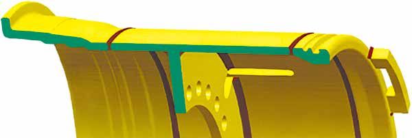
(1) EUW, EU type rim with rim diameter 63 inches
The contact shapes of rim components (rim bases, lock rings, bead seat bands, side rings) for EUW
type and EU type rims vary. Always make sure you assemble them correctly.
Diagrams showing the correct assembly of EUW type rim components and EU type rim components
EUW type rim W type side ring W type side ring
(reinforced type) Tapered shape Tapered shape
HSW type bead seat band 35 degrees
EUW type rim base
EUS type lock ring
EU type rim Standard type side ring Standard type side ring
(standard type) Not tapered Not tapered
HS type bead seat band 45 degrees
EU type rim base
EU type lock ring
Characteristics of EUS, EU type 63-inch rim diameter
Verify the grooves and markings to distinguish between EUS and EU type lock rings
Rim type EUS type EU type
Rim base diam eter 61” 60.5” 60.5”
Rim base EUWA type EUW type EU type
Lock ring LR63EUSB LR63EUS LR63EU
Bead seat band BB7563HSWB BB7563HSW BB7563HS
Side ring SB5063SW SB5063SW SB5063S
Grooves for identification
Lock ring
Cross-sectional shape 45
Marking EUSB EUS EU
18 (2017.03) (2017.03) 187. Examples of potentially hazardous matches
Examples of name (Stamp) of 63” rim and components
Rim size Rim component, size and type (Typical identification)
(Dia×width/ Typical Tyre Bead Seat
Flange height) Rim base Lock ring Side ring
Band
EUW(60.5") EU D4463EU LR63EU BB7563HS SR5063SB
EUW D36.00x63 EUWAIR LE63EUS BB7563HSWA SR5063SWB
SRM36.00x63EUWIR LR63EUSH BB7563HSWFI SR5063SWB
S36.00x63EUW AC STS LR63EUS2 BB7563HSWI SR5063SWB
D4163EUW LR63EUSA BB7563HSW SR5063SWB
D41.00x63EUW STS LR63EUS2 BB7563HSWA SR5063SWBT
D44.00x63EUWIR LE63EUS BB7563HSWVI SR5063SWD
EUWA(61") EUWA D3663EUWA LR63EUSBH BB7563HSWBA SR5063SWB
RM44.00x63EUWA IP LR63EUSBH BB7563HSWCA SR5063SWBT
RM44.00x63EUWA FP LR63EUSBH BB7563HSWHI SR5063SWBT
D44.00x63EUWA IP LR63EUSBH BB7563HSWCA SR5063SWBT
D4463EUWA SSS LR63EUSBH BB7563HSWCA SR5063SWBT
Warning
Check the rim component markings and confirm that the combination of rim components is correct using
the matching charts.
Incorrect assembly could lead to a fatal accident. Always verify the compatibility of components before
assembling.
Lock ring ends should not touch after assembled.
19
18 (2017.03)7. Examples of potentially hazardous matches
(2) Rim base and lock ring combination
For rim diameters 63, 57, 51 inches
On gutters of EU type and EJ type rim bases, or on gutters of other manufacturers rim base, the
shape of the lock ring groove differs. Ensure that they are combined with the correct lock ring.
Lock ring (manufactured by
another company
Here to refer to
Gutter band EU type EJ type PHASE2 the note below)
CORRECT WRONG WRONG
EU type
WRONG CORRECT WRONG
EJ type
WRONG WRONG CORRECT
PHASE2
(manufactured by
another company
Here to refer to
the note below)
CORRECT : Correct combination WRONG : Wrong combination
* PHASE: PHASE is manufactured by another company. As far as TOPY Industries is aware of,
this is the current name by which this lock ring is referred to in the industry. Please note that the
name and/or shape may change in the future.
Warning
/Check the rim component markings and confirm that the combination of rim components is correct using
the matching charts.
/ NEVER mix TOPY rim components with PHASE type rim components manufactured by another company.
Incorrect assembly could lead to a serious injury or death. Always verify the compatibility of components
before assembling.
(2017.03)
(2008.08) 20
197. Examples of potentially hazardous matches
(2) Rim base and lock ring combination (cont'd)
For rim diameter 49, 35, 33 inches
On gutter of EV type and EM type rim bases, the shape of the lock ring groove differs. Make sure
that they are combined with the correct lock ring.
Lock ring
Gutter EV type EM type
CORRECT WRONG
EV type
WRONG CORRECT
EM type
CORRECT : Correct combination WRONG : Wrong combination
Warning
/ Check the rim component markings and confirm that the combination of rim components is correct using
the matching charts.
/Incorrect assembly could result in serious injury or death. Always verify the compatibility of components
before assembling.
21
20 (2017.03)
(2008.08)7. Examples of potentially hazardous matches
(3) Lock ring and bead seat band combination
For rim diameter 63,57,51 inches
On EUS type and EU type lock rings, or on lock rings of other manufacturers, the contact angle with
the bead seat band differs. Make sure that they are combined with the correct bead seat band.
Lock ring 35 45 (Manufactured by
another company
Here to refer to
the note below)
Bead
seat band EUS type EU type TSR type
35 CORRECT WRONG WRONG
35
ESU type
WRONG CORRECT WRONG
45
HS type
WRONG WRONG CORRECT
TSR type
(Manufactured by another
company Here to refer to
the note below)
CORRECT : Correct combination WRONG : Wrong combination
TSR : TSR is made by another company. As far as TOPY Industries is aware
of, this is the current name which this part is referred in the industry.
Please note that the name and/or shape may change in the future.
Characteristic of EUS, EU type lock ring and bead seat band
Rim Type EUS EU
Lock ring EUS type EU type
Bead seat band HSW type, ES type HS type
Lock ring and bead seat
band contact angle 35 degree 45 degree
Grooves for identification
Lock ring 45
cross-sectional shape
35°
Warning
Check the rim component markings and confirm that the combination of rim components is correct using
the matching charts.
Incorrect assembly could result in serious injury or death. Always verify the compatibility of components
before assembling.
(2017.03)
(2008.08) 22
217. Examples of potentially hazardous matches
(3) Lock ring and bead seat band combination (cont'd)
For rim diameters 49”,45,39,35,33 inches
On EV type, EM type and ES type lock rings, the contact angle and/or retaining mechanism with the
bead seat band differs. Make sure that they are combined with the correct bead seat band.
Lock ring 45° 35°
Bead
seat band EV type EM type ES type
CORRECT CORRECT WRONG
45°
EV type
WRONG CORRECT WRONG
EM type
WRONG WRONG CORRECT
35°
ES type
CORRECT : Correct combination WRONG : Wrong combination
Characteristic of EV, EM and ES type lock ring and bead seat band
Rim Type EV EMV EM ES
Lock ring EV type EM type EM type ES type
Bead seat band EV type EV type EM type ES type
LR and BB contact angle 45 degree 45 degree 45 degree 35 degree
Lock ring 45
cross-sectional 35°
shape
Bead seat band
45°
cross-sectional 35°
shape
Warning
Check the rim component markings and confirm that the combination of rim components is correct using
the matching charts.
Incorrect assembly could lead result in serious injury or death. Always verify the compatibility of
components before assembling.
23
22 (2017.03)
(2008.08)7. Examples of potentially hazardous matches
(4) Facing of lock ring
The correct installation of the locking ring can only be achieved if the markings on the locking ring
can be seen before, during, and after installation.
If the locking ring is installed back to front it will not interface properly with the gutter band and
there is a risk of the locking ring dislodging under pressure.
For WI type lock ring
Correct facing Wrong facing
CORRECT WRONG
Markings Markings
are visible are not visible
Warning
/ Prior to installing the locking ring, confirm that the locking marking is visible so that the installation can
be carried out correctly.
/If the locking ring is installed back to front, the markings are not visible, and continuing assembly could
result in an explosion and serious injury or death.
(2017.03)
(2008.08) 24
238. Procedures for servicing tyres and TOPY rims
8. Procedures for servicing tyres and TOPY rims
Warning
/Servicing tyres and rims can be very dangerous. Failing to heed the warnings could result in serious
injury or death.
/Servicing of tyres and rims should be carried out only by workers who have received adequate training
from a qualified supervisor on safe handling of tyres and rims. This training must include reading this
manual completely.
/Tyres should be deflated while standing outside the range of the “hazardous trajectory” shown by the
arrows in the diagram below. Exercise extreme caution as the direction of the trajectory may widen.
/While deflating, DO NOT allow other workers or third parties to approach the area of the trajectory.
/Check the “Tyre and Rim Handling Manual” published by the tyre manufacturer for information on work
and inspections, etc. involving tyre handling.
/There are several types of tools for servicing work. Be sure you have a proper understanding of how the
tools are used and carry out the work in accordance with the proper procedure.
/Ensure that protective equipment is worn when servicing tyres and rims.
(Wear gloves, safety shoes, safety glasses, face protection, earplugs, hard hat, etc.)
/If there are any doubts during demounting, mounting, or inflating tyres and rims, immediately stop the
work in progress and seek instruction from a supervisor.
Hazardous
trajectory
Hazardous
trajectory
25
24 (2017.03)
(2008.08)8.1 How to demount tyre from TOPY 3-piece rim
[Required tools]
•Valve tool •Wire for valve cleaning •Wire brush
•Tyre lever for tyre mount/demount (confirm specifications of tool type with your tyre dealer)
•Lifting equipment (crane, chains, nylon sling, forklift, tyre handler, etc.)
STEP
1 Release all air
D Prior to demounting tyre from rim, release all air by removing the valve core housing with the valve tool.
Valve core housing
Valve
Valve tool
Warning
/ First, remove the valve core and release all air from the tyre.
/ Be aware of the trajectory of the valve core as it may shoot out during its removal.
/If there is any foreign matter inside the valve, the air will not be released. Insert wire, etc. into the valve
to clear away foreign matter.
/ When removing tyre and rim from a vehicle, prior to removing the parts (clamps, nuts, etc.), secure the
rim base accessories (extension valve fixing brackets, etc.) and rim base to the vehicle and release all
air from the tyre.
/ When demounting outer tyres and rims of dual assemblies, make sure you release all air from the inner
tyres as well.
/ Tyres should be deflated outside the range of the “hazardous trajectory” shown by the arrow in the
diagram below. Exercise extreme caution as the range of the trajectory may widen.
/ During deflation work, DO NOT allow other workers or third parties to approach the area of the trajectory.
/ When releasing air, stand in a safe location as foreign matter or frozen particles inside tyre might be
discharged.
/ Do not allow high pressure air to hit skin.
Hazardous
trajectory
Hazardous
trajectory
(2017.03)
(2008.08) 26
258.1 How to demount tyre from TOPY 3-piece rim
STEP
2 Set up the tyre and rim
D After fully releasing the air, place the Gutter
tyre and rim on the ground with the UP
gutter side facing up.
Warning
/Because this work involves handling heavy items, where necessary, you must use appropriate lifting
equipment.
/ When moving tyres and rims, be careful to avoid accidental drops or falls that could injure you or others
in the vicinity.
STEP
3 Detach tyre bead seat from side ring
D Insert the tyre lever between the tyre bead and the side
ring. Unseat the bead from the side ring by using the lever
to push the tyre down around the entire circumference.
Warning
/ When mounting and demounting tyres, maintain a firm grip on the tyre lever as it may jerk loose and
cause injury.
27
26 (2017.03)
(2008.08)8.1 How to demount tyre from TOPY 3-piece rim
STEP
4 Remove lock ring
Use the tyre lever to lift one end of the locking ring from
the locking ring groove.
With a second tyre lever continue to dislodge the locking
ring around the circumference of the rim until the locking
ring is free from the assembly.
Never Reuse USE
Ends are open
Warning
Discard lock rings with open ends (ends aren't touching) as they will not set correctly (see above) and
could result in serious injury or death.
When removing the lock ring, DO NOT spread the ends excessively as they will no longer touch and will
have to be discarded.
Keep fingers away from lock ring.
Be careful when removing the lock ring as it may literally fly off as it is being freed.
Maintain a firm grip on the tyre lever as it may be thrown and cause injury.
(2008.08)
(2017.03) 27
288.1 How to demount tyre from TOPY 3-piece rim
STEP
5 Remove O-ring
D Use the tyre lever to push down on the side ring so that
the O-ring may be removed. Remove the O-ring.
Warning
/ Keep fingers away from side ring.
/ When mounting and demounting tyres, maintain a firm grip on the tyre lever as it may be jerk loose and
cause injury.
Notice
Once used, O-rings become deformed and can result in air leaks. Used O-rings should be cut and discarded.
STEP
6 Remove side ring
D Use the tyre lever to remove the side ring.
Warning
/ Keep fingers away from side ring.
/ When mounting and demounting tyres, maintain a firm grip on the tyre lever as it may be jerk loose and
cause injury.
/ Be careful not to drop components on your feet.
29
28 (2017.03)
(2008.08)8.1 How to demount tyre from TOPY 3-piece rim
STEP
7 Turn over tyre and rim
D Use lifting equipment to turn over the tyre and rim, and
place them on the ground.
Warning
/ Because this work involves handling heavy items, where necessary, you must use appropriate lifting
equipment.
/ When moving tyres and rims, be careful to avoid accidental drops or falls that could injure you or others
in the vicinity.
STEP
8 Detach tyre bead from rim base, and remove rim base.
D As in Step 3, insert the tyre lever between the tyre bead
and the rim base.
J Push down the tyre around the entire circumference, and
detach tyre bead from the rim base.
8 Remove the rim base.
Warning
/ Because this work involves handling heavy items, where necessary, you must use appropriate lifting
equipment.
/ When moving tyres and rims, be careful to avoid accidental drops or falls that could injure you or others
in the vicinity.
/ Be careful not to get your fingers caught.
/ When mounting and demounting tyres, maintain a firm grip on the tyre lever as they may jerk loose and
cause injury.
(2017.03)
(2008.08) 30
298.2 How to mount tyre onto TOPY 3-piece rim
[Required tools]
•Valve tool •Wire for cleaning valve core •Tyre seating blocks
•Tyre lever for tyre mount/demount (confirm specifications of tool type with your tyre dealer)
•Soft metal or hard plastic hammer (not steel)
•Lifting equipment (crane, chains, nylon sling, forklift, tyre handler, etc.)
•Lubricant for tyre mounting (product recommended by tyre dealer)
•Wire brush •Air gauge •Air chuck
STEP
1 Confirm tyre and rim component combination
D Check tyre size and markings on rim base, and make sure that the combination is correct.
J Check markings on rim components and matching charts, and make sure that the combination is correct.
Warning
/ Confirm tyre and rim combinations with your tyre dealer or confirm using the specifications for tyres and
rims.
/Check the rim component markings and confirm that the combination of rim components is correct using
the matching charts. The wrong combination could cause “explosive separation of the rim” resulting in
severe injury or death to workers and bystanders.
/ DO NOT combine TOPY rim components with rim components manufactured by other companies.
/ If there are any doubts concerning combinations or matching charts, immediately suspend the work in
progress and contact your TOPY rim dealer.
STEP
2 Clean rim components and check condition
D Clean rim components with a wire brush so that examination,
maintenance, and mounting can be done correctly.
J Check that there is no deformation, bent, cracking, wear,
corrosion, or damage on the rim components.
Warning
/ Discard any rim components that are deformed, bent, cracked, weared corroded, or damaged, or are
suspected of being so, and replace them with undamaged components.
/ Discard any lock rings with open ends (ends aren't touching).
/ DO NOT make modifications that change the product specifications.
/DO NOT make modifications involving welding, heating, soldering, etc. Such modifications could lead
to the deformation as well as the deterioration of the strength and structural integrity of the rim
components.
Notice
If there's any foreign matter, etc. adhering to the lock ring grooves on the rim base or to O-ring grooves, proper
assembly will not be possible and air leaks will occur. Make sure all grooves are clean before assembly.
31
30 (2017.03)
(2008.08)8.2 How to mount tyre onto TOPY 3-piece rim
STEP
3 Recoat
DRecoat any areas where the anti-corrosive oil or paint is peeling.
Caution
/ Anti-corrosive oil and paint may contain toxic ingredients. Follow any safety instructions provided by the
manufacturers of the anti-corrosive oil or paint.
/Depending on the vehicle, some parts have certain areas that may be uncoated in order to prevent
loosening of parts attaching the rim base to the vehicle (clamps, nuts, etc.) and slipping of rim
components, etc. If you're not sure, check with the vehicle manufacturer or your TOPY rim dealer.
STEP
4 Set up rim base and install valve
DPlace rim base on rim base stand with gutter side up.
JInstall valve.
Warning
/ Because this work involves handling heavy items, where necessary, you must use appropriate lifting
equipment.
/ When moving rim components, be careful to avoid accidental drops or falls that could injure you or
others in the vicinity.
/For valve selection and installation, follow instructions in the manuals provided by your tyre dealer and
valve manufacturer. If in doubt, contact the dealer or manufacturer for guidance.
STEP
5 Confirm absence of tyre defects
DConfirm absence of tyre defects.
Warning
/Check with tyre dealer to confirm that there are no tyre defects. Using defective tyres could result in tyre
failure while you are mounting the tyre and rim or during use, resulting in tyre separation and possible
severe injury or death.
(2017.03)
(2008.08) 32
318.2 How to mount tyre onto TOPY 3-piece rim
STEP
6 Mount tyre on rim base
D Apply a vegetable oil-based lubricant to both tyre
bead seats.
J Place tyre on rim base.
Notice
/DO NOT apply tyre lubricant to areas other than where the rim components come in contact with the tyre.
Doing so could cause circumferential slippage between rim components when the vehicle is being driven.
/Consult your tyre dealer when selecting tyre lubricant.
Warning
/Because this work involves handling heavy items, correctly use lifting equipment when necessary.
/When moving rim components, be careful to avoid accidental drops or falls that could injure you or
others in the vicinity.
STEP
7 Fit side ring
DInsert side ring into rim base and fit edge section to tyre bead.
Caution
/ Keep fingers away from side ring.
33
32 (2017.03)
(2008.08)8.2 How to mount tyre onto TOPY 3-piece rim
STEP
8 Fit O-ring
DApply lubricant to new O-ring and install it in the O-ring
groove.
Caution
/ Keep fingers away from side ring.
Notice
/Check with your tyre dealer for O-ring specifications or when selecting lubricant.
/Be careful not to twist the O-ring.
(2017.03)
(2008.08) 34
338.2 How to mount tyre onto TOPY 3-piece rim
STEP
9 Fit lock ring
DPlace the end of the lock ring into the lock ring groove in the rim base. Use the tyre lever to
successfully install the lock ring around the entire circumference.
JStarting opposite the locking ring gap, lightly tap the locking ring with a soft metal or hard plastic
hammer in both directions back to the locking ring gap to ensure the locking ring is clamped into
the locking ring groove.
Never Use USE
Ends are open
Warning
/DO NOT use lock rings with open ends (ends aren't touching).
/ Check the facing of the lock ring. The lock ring is installed correctly if its markings are visible after tyre assembly.
/ DO NOT use a steel mallet.
Caution
/ Be careful when handling the lock ring as it may fly off.
/ Be careful not to get your fingers caught.
35
34 (2017.03)
(2008.08)8.2 How to mount tyre onto TOPY 3-piece rim
STEP
10 Confirm that rim components are assembled correctly
DMake sure the combinations (matching), facings, and positions of rim components are correct.
Warning
/ Recheck the tyre and rim component combinations (matching) and make sure they are correct.
/ Recheck the facing of the lock ring and make sure it is installed correctly and is securely in the lock ring groove.
/DO NOT inflate, hammer, weld or solder to position the rim components. Doing so can lead to the
deformation as well as the deterioration of the strength and structural integrity of the rim components.
STEP
11 Inflating the tyre and rim
Tyre inflation safety cage
DWherever possible, place tyre and rim inside a tyre
inflation safety cage, then inflate tyre. During inflation,
keep away from the tyre.
JWhen tyre has been inflated to a pressure of approximately
35kPa (5psi), check assembly of tyre and rim components.
8If assembled correctly, continue inflating up to the rated
value.
Warning
If assembly has been done incorrectly, inflation could result in an explosive separation of the rim. This
separation could result in serious injury or death to you or bystanders. Workers and persons responsible
for supervising the work must comply strictly with the following warnings.
/ Wherever possible, ensure that the work is carried out with the tyre inside a tyre inflation safety cage.
/ While inflating, workers and bystanders must always be outside the range of the “hazardous trajectory”.
Exercise extreme caution as the trajectory may widen.
/ During inflation, use an air pressure gauge and regulator valve.
/ To ensure that the worker inflating the tyre can remain outside of the "hazardous trajectory", use an air
pressure gauge and a hose of adequate length, and use an air chuck.
/ During inflation, DO NOT allow the air pressure to exceed the pressure recommended by tyre
manufacturer.
/ If you notice a mistake in the assembly, immediately stop inflation, release the air, and reassemble the
tyre and rim components.
/NEVER attempt to position the rim components by inflating the tyre.
/Because this work involves handling heavy items, correctly use lifting equipment when necessary.
/When moving rim components, be careful to avoid accidental drops or falls that could injure you or others in the
vicinity.
/Lay the assembled and inflated tyre rim so it is flat and stable and not subject to impacts.
Notice
In order to prevent corrosion of the rim components, inflate tyres with dry air.
(2017.03)
(2008.08) 36
358.3 How to demount tyre from TOPY 5-piece rim
[Required tools]
•Valve tool •Wire for valve cleaning
•Tyre lever for tyre mount/demount (confirm specifications of tool type with your tyre dealer)
•Lifting equipment (crane, chains, nylon sling, forklift, tyre handler, etc.)
•Hydraulic bead breaker
STEP
1 Release all air
D Prior to demounting tyre from rim, release all air by removing the valve core housing with the valve tool.
Valve core housing
Valve
Valve tool
Warning
/ First, remove the valve core and release all air from the tyre.
/ Be aware of the trajectory of the valve core as it may shoot out during its removal.
/If there is any foreign matter inside the valve, the air will not be released. Insert wire, etc. into the valve
to clear away foreign matter.
/When removing tyre and rim from a vehicle, prior to removing the parts (clamps, nuts, etc.), secure the rim
base accessories (extension valve fixing brackets, etc.) and rim base to the vehicle and release all air from the
tyre.
/When demounting outer tyres and rims of dual assemblies, make sure you release all air from the inner
tyres as well.
/Tyres should be deflated outside the range of the “hazardous trajectory” shown by the arrow in the
diagram below. Exercise extreme caution as the range of the trajectory may widen.
/During deflation work, DO NOT allow other workers or third parties to approach the area of the trajectory.
/When releasing air, stand in a safe location as foreign matter or frozen particles inside tyre might be
discharged.
/ Do not allow high pressure air to hit skin.
Hazardous
trajectory
Hazardous
trajectory
37
36 (2017.03)
(2008.08)8.3 How to demount tyre from TOPY 5-piece rim
STEP
2 Set up tyre and rim
D After fully releasing the air, place the Gutter
tyre and rim on the ground with the UP
gutter side facing up.
Warning
/ Because this work involves handling heavy items, correctly use lifting equipment when necessary.
/ When moving tyres and rims, be careful to avoid accidental drops or falls that could injure you or others
in the vicinity.
STEP
3 Unseat the tyre bead from the bead seat band
D Mount bead breaker on bead seat band.
J Operate the bead breaker, push down the side ring, and
unseat the tyre bead from the bead seat band.
Caution
/ Be careful not to get your fingers caught.
/ When loading using the bead breaker, stand to one side and carry out the work carefully as the bead
breaker could fly off.
/ DO NOT apply tools to welded areas of the bead seat band, side ring, or rim base. If welds are damaged,
discard the component.
/ When handling the bead breaker, refer to the instructions provided by the manufacturer.
(2017.03)
(2008.08) 38
378.3 How to demount tyre from TOPY 5-piece rim
STEP
4 Remove driver key
For rims fitted with a driver key, remove the driver key.
Caution
Be careful not to get your fingers caught.
STEP
5 Remove lock ring
Use a tyre lever to force the bead seat band free from the
locking ring.
Use the tyre lever to leave out one end of the locking ring
from the locking groove.
With a second tyre lever, continue to dislodge the locking
ring around the circumference of the rim until the locking
ring is free from the assembly.
Never Reuse USE
Ends are open
Warning
Discard lock rings with open ends (ends aren't touching) as they will not set correctly (see above) and
could result in serious injury or death.
When removing the lock ring, DO NOT spread the ends excessively as they will no longer touch and will
have to be discarded.
Keep fingers away from lock ring.
Be careful when removing the lock ring as it may literally fly off as it is being freed.
Maintain a firm grip on the lever tools as they may jerk loose and cause injury.
38
39 (2008.08)
(2017.03)You can also read