SMARTFUSION2/IGLOO2 FABRIC LAB GUIDE - TRENZ ELECTRONIC ...
←
→
Page content transcription
If your browser does not render page correctly, please read the page content below
SmartFusion2/IGLOO2 Fabric Lab Guide
SmartFusion2/IGLOO2 Fabric Lab Guide

Microsemi PRO BU, San Jose, CA 95134

© 2019 Microsemi Corporation. All rights reserved.

Printed in the United States of America

Release: March 2019

Microsemi makes no warranties with respect to this documentation and disclaims any implied warranties of
merchantability or fitness for a particular purpose. Information in this document is subject to change without notice.
Microsemi assumes no responsibility for any errors that may appear in this document.

This document contains confidential proprietary information that is not to be disclosed to any unauthorized person
without prior written consent of Microsemi Corporation.

Trademarks

Microsemi, SmartFusion2, IGLOO2 and the associated logos are trademarks or registered trademarks of Microsemi
Corporation. All other trademarks and service marks are the property of their respective owners.

Page 2 of 42                                                 v3.1
SmartFusion2/IGLOO2 Fabric Lab Guide

Table of Contents
Table of Contents.................................................................................................................................... 3
Introduction ........................................................................................................................................... 4
   Components Used in the Design ....................................................................................................................... 4
   Tutorial Requirements ...................................................................................................................................... 5
   Extracting the source files ................................................................................................................................. 5

Step 1 – Creating the Design ................................................................................................................... 5
   Launching Libero SoC and creating a project...................................................................................................... 5
   Implementing the design with SmartDesign .................................................................................................... 11

Step 2 - Simulating the design ............................................................................................................... 19
Step 3 – Editing the I/O Physical Constraint file ..................................................................................... 25
Step 4 - Generating Timing Constraints ................................................................................................. 27
Step 5 – Synthesis and Layout ............................................................................................................... 28
Step 6 – Programming .......................................................................................................................... 32
   Running the Application ................................................................................................................................. 33

Step 7 - Debugging with SmartDebug ................................................................................................... 34
   SmartDebug Live Probes ................................................................................................................................. 34
   SmartDebug Active Probes ............................................................................................................................. 36

Record answers to questions below ...................................................................................................... 39
Answers to Questions (results can slightly vary on your system) ............................................................ 40
List of Figures ....................................................................................................................................... 41

Page 3 of 42                                                                       v3.1
SmartFusion2/IGLOO2 Fabric Lab Guide

Introduction
This tutorial demonstrates how to implement a basic SmartFusion2 / IGLOO2 FPGA fabric design using SmartDesign.
The design drives several LEDs on the SmartFusion2 or IGLOO2 target board. A counter output is used to drive the
LEDs. The SmartDebug Live Probes are used to drive another LED on the target board.
After completing this tutorial, you will be familiar with the following:

    •   Creating a Libero SoC project
    •   Implementing a SmartFusion2 / IGLOO2 fabric design with SmartDesign
    •   Simulating the design
    •   Importing a PDC file, running layout and programming the SmartFusion2 / IGLOO2 silicon
    •   Using the SmartDebug Live Probes

Components Used in the Design
This tutorial uses the SmartFusion2 / IGLOO2 FPGA fabric, the on-chip 25/50 MHz RC oscillator and the Fabric CCC
and Live Probe A.

Page 4 of 42                                                   v3.1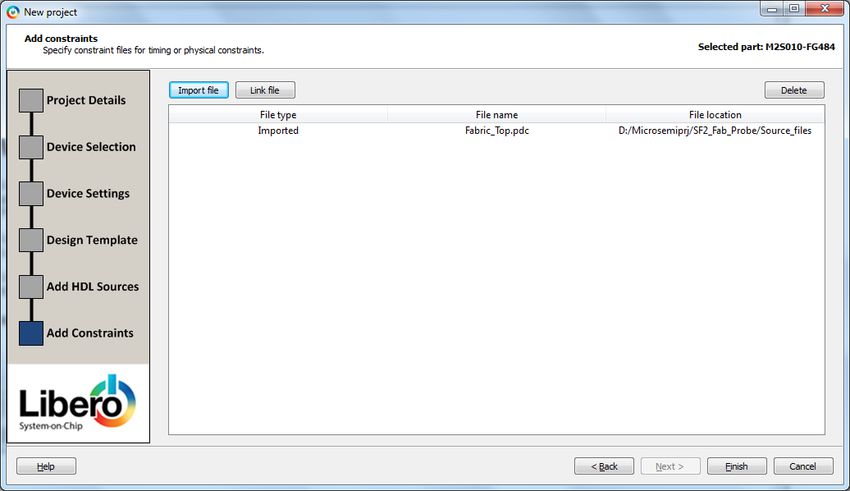
SmartFusion2/IGLOO2 Fabric Lab Guide

Tutorial Requirements
Software Requirements
This tutorial requires the following software installed on your computer:

    •   Microsemi Libero SoC v12.0

Hardware Requirements
This tutorial can be used with the following SmartFusion2 board:

    •   SMF2000 SmartFusion2 board

Note: The Free Libero Silver license can be used with this kit.

Extracting the source files
Extract SF2_Fab_Probe.zip to extract the required lab files to the \Microsemiprj folder on the HDD of your
PC. Confirm that a folder named SF2_Fab_Probe containing a sub-folder named Source_files was extracted.

Step 1 – Creating the Design
In this step you will create the fabric design using SmartDesign. Some source files have been provided in the
Source_files folder.

Launching Libero SoC and creating a project
1. Click Start > Programs > Microsemi > Libero SoC v12.0, or click the shortcut on your desktop. The Libero SoC
   Project Manager will open.

                                            Figure 1 - Libero SoC Project Manager

Page 5 of 42                                                    v3.1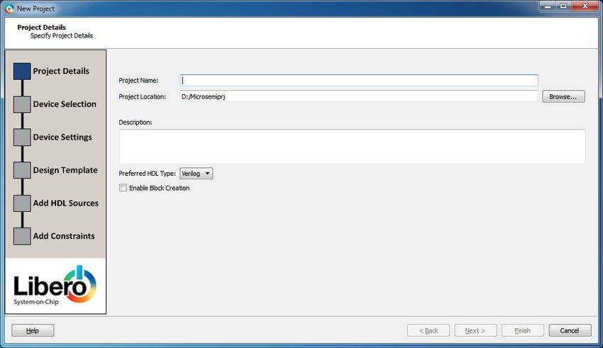
SmartFusion2/IGLOO2 Fabric Lab Guide
2. Create a new project by selecting New on the Start Page tab (circled in the figure above), or by clicking Project >
New Project from the Libero SoC menu. The New Project wizard will open.
Figure 2 - Libero SoC New Project dialog box
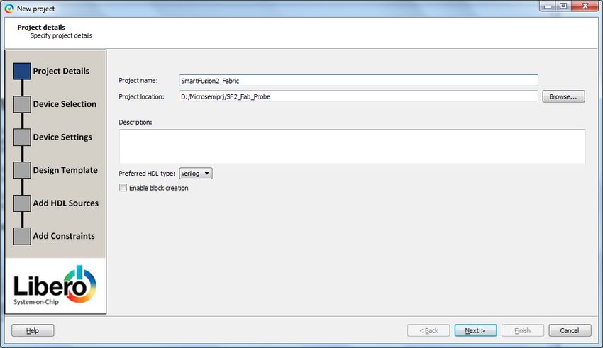
3. Enter the information shown below in the Project Details page of the New Project dialog box then click Next:
• Project Name: SmartFusion2_Fabric
• Project Location: \Microsemiprj\SF2_Fab_Probe (depending on where you extracted the source
files)
• Preferred HDL type: Verilog or VHDL, select VHDL for this lab example
• Enable Block Creation: un-checked
Figure 3 - Project Details
Page 6 of 42 v3.1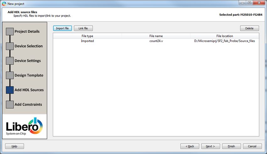
SmartFusion2/IGLOO2 Fabric Lab Guide
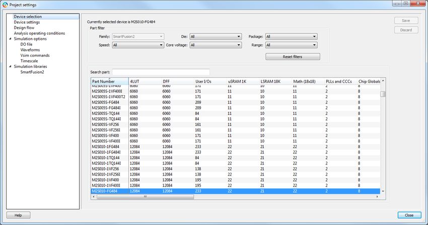
4. Enter the following in the Device Selection page of the New Project dialog box, select M2S010-VF400 device then
click Next:
o Family: SmartFusion2
o Die: M2S010
o Package: 400 VF
o Speed: STD
o Core Voltage(V): 1.2
o Range: COM
Figure 4 - Device selection (settings for SMF2000 board shown)
5. Enter the following in the Device Settings page of the New Project dialog box then click Next:
• Default I/O Technology: LVCMOS 3.3V
• Reserve Pins for Probes: checked (default)
• Power Supplies
o PLL Supply Voltage (V): 3.3V
o Ramp rate: 100ms (default)
o System Controller Suspend Mode: un-checked
The PLL Supply voltage can be either 2.5V or 3.3V. The voltage setting in the New Project dialog box must match
the PLL Analog Supply voltage on the board to ensure the PLL works correctly.
Page 7 of 42 v3.1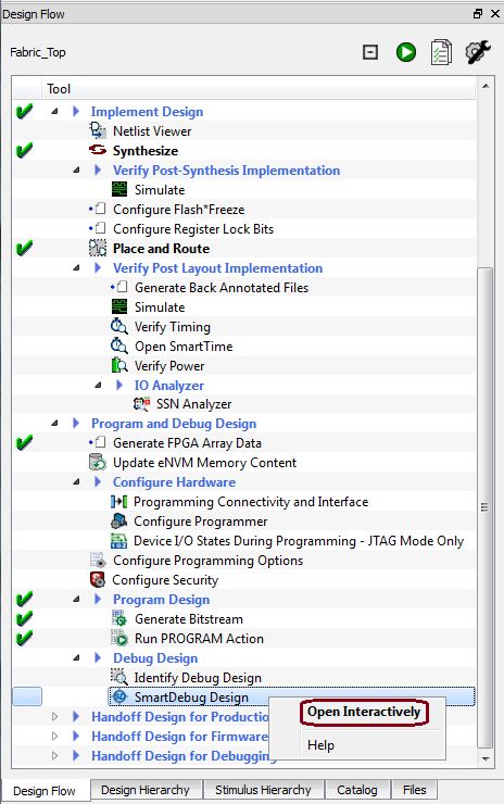
SmartFusion2/IGLOO2 Fabric Lab Guide

                             Figure 5 - Device Settings (settings for SMF2000 board shown)

6. Enter the following in the Design Template page of the New Project dialog box then click Next:
   • Design Templates and Creators: None (this design does not use the SmartFusion MSS or IGLOO2 HPMS)
   • Design Methodology:
       o Use Standalone Initialization for MDDR/FDDR/SERDES peripherals: un-checked
       o Instantiate SystemBuilder/MSS component in a SmartDesign on creation: checked

                                      Figure 6 - Design Template settings (all kits)

Page 8 of 42                                                   v3.1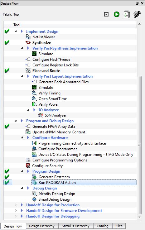
SmartFusion2/IGLOO2 Fabric Lab Guide

7. The Add HDL Source Files page will be visible. A VHDL source file has been provided. Import the file into the
   project by clicking Import File.
8. Enter the following in the Import Files dialog box then click Open:
   • Location:           \Microsemiprj\SF2_Fab_Probe\Source_files
   • File name:         count24.vhd
   • Files of type: HDL Source Files (*.vhd *.v *.h)

                                            Figure 7 - Imported HDL source files

9. Click Next. The Add Constraints page will be visible. An I/O constraint file has been provided. Import the file
   into the project by clicking Import File.

Page 9 of 42                                                    v3.1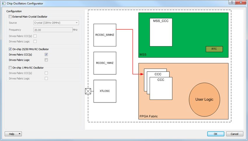
SmartFusion2/IGLOO2 Fabric Lab Guide

10. Enter the following in the Import Files dialog box then click Open:
    • Location:          \Microsemiprj\SF2_Fab_Probe\Source_files
    • File name:         Fabric_Top.pdc
    • Files of type: I/O Constraint Files (*.pdc)

                                              Figure 8 - Imported I/O Constraint file

11. Click Finish in the New Project dialog box.

12. The HDL source file will be visible on the Design Hierarchy tab after clicking Build Hierarchy. Both the HDL source
    file and the I/O constraint file will also be visible on the Files tab.

                                  Figure 9 - HDL source file and I/O constraint file in Libero SoC

Page 10 of 42                                                       v3.1
SmartFusion2/IGLOO2 Fabric Lab Guide
Implementing the design with SmartDesign
1. Open the SmartDesign canvas by selecting File > New > SmartDesign from the menu or by double-clicking Create
SmartDesign under Create Design on the Design Flow tab.
Figure 10 - Opening the SmartDesign canvas
2. Enter Fabric_Top in the Create New SmartDesign dialog box then click OK. Save the component with
CTRL+SHIFT+S.
Figure 11 - Entering SmartDesign name
3. Click Build Hierarchy & Drag the count24 component from the Design Hierarchy tab to the SmartDesign canvas.
This design uses a fabric CCC to generate the 1 MHz internal clock. The CCC reference clock is the 25/50 MHz RC
oscillator. In the next steps you will configure the CCC to output a 1 MHz clock and configure the on-chip oscillator.
4. Expand Clock & Management in the IP catalog.
Figure 12 - Clock & Management category of the Libero SoC IP Catalog
5. Drag an instance of the Clock Conditioning Circuitry (CCC) v2.0.201 component into the SmartDesign canvas.
6. FAB CCC Configurator will open, otherwise double-click the FCCC_0 component in the SmartDesign canvas to
open the FAB CCC Configurator.
Page 11 of 42 v3.1SmartFusion2/IGLOO2 Fabric Lab Guide
7. Select the Basic tab in the FAB CCC configurator. Enter the following:
• Reference clock: Select Oscillators > 25/50 MHz Oscillator from the pull-down menu
• GL0: checked;
o Exact Value: checked
o Frequency: 1 MHz
Figure 13 - Configuring the fabric CCC
8. Click OK to close the FAB CCC Configurator.
9. Drag an instance of the Chip Oscillators v2.0.101 component from the IP catalog into the SmartDesign canvas.
10. Chip Oscillators Configurator will open, otherwise double-click the OSC_0 component in the SmartDesign canvas
to open the Chip Oscillators configurator.
11. Configure the 50 MHz RC oscillator to drive the fabric CCC as follows:
• Enable the On-chip 25/50 MHz RC Oscillator
• Select Drives Fabric CCC(s)
Page 12 of 42 v3.1SmartFusion2/IGLOO2 Fabric Lab Guide
Figure 14 - Configuring the Chip Oscillators (SmartFusion2 target)
12. Click OK to close the Chip Oscillators configurator.
13. Expand Macro Library in the Libero SoC IP catalog.
Figure 15 – Macro Library category of the Libero SoC IP Catalog
Page 13 of 42 v3.1SmartFusion2/IGLOO2 Fabric Lab Guide
14. Drag an instance of AND2 and SYSRESET into the SmartDesign Canvas.
Tip: to make it easier to find the macros listed above, type a few letters of the macro name followed by * in the
IP Catalog search field. When finished, change the field to * to display the entire catalog.
Figure 16 - IP Catalog Search field
15. Drag an instance of LIVE_PROBE_FB into the SmartDesign Canvas. The LIVE_PROBE_FB macro allows the
SmartDebug Live Probes to be re-directed into the FPGA fabric. One of the outputs will be connected to an LED
on the target board.
16. After adding the components, the SmartDesign will resemble the figure below. If needed, drag the components
to improve the appearance of the canvas.
Tip: expand the canvas area by selecting View > Maximize Work Area or click the icon on the tool bar ( ).
Figure 17 - SmartDesign canvas after adding components
Page 14 of 42 v3.1SmartFusion2/IGLOO2 Fabric Lab Guide
Making connections in the canvas
Next connect the components in the SmartDesign canvas to complete the design. SmartDesign in Libero SoC has a
connection mode that supports click, drag and release to make connections.
17. Select SmartDesign > Connection Mode from the Libero SoC menu or click the Connection Mode icon ( ).
18. Connect the RCOSC_25_50MHZ_CCC_OUT port of OSC_0 component to the RCOSC_25_50MHZ_CCC_IN port of
the FCCC_0 component as follows:
• Click and hold mouse button on the RCOSC_25_50MHZ_CCC_OUT port of the OSC_0 component.
• Drag mouse to the RCOSC_25_50MHZ_CCC_IN port of FCCC_0 component.
• Release mouse button on the RCOSC_25_50MHZ_CCC_IN port to make the connection.
19. Repeat the previous step to make the connections shown it the table below.
From To
FCCC_0:GL0 count24_0:CLK
FCCC_0:LOCK AND2_0:A
SYSRESET_0:POWER_ON_RESET_N AND2_0:B
AND2_0:Y count24_0:RESETn
Table 2 – SmartDesign canvas connections
20. Disable the SmartDesign connection mode by selecting SmartDesign > Connection Mode from the Libero SoC
menu.
21. Promote the UP_DN port from count24_0 to the Top Level by selecting the UP_DN port and choosing Promote
to Top Level from the popup menu (click right mouse button).
22. Rename UP_DN port to USER_BTN by choosing Rename Top Level Pin from the popup menu (click right mouse
button).
23. Expose bits 16 to 23 of count24_0 by selecting port Q[23:0] of count24_0 then right-clicking and selecting Edit
Slice.
Figure 18 - Adding a slice to the Q[23:0] output
24. Click the + sign (circled in the figure below) in the Edit Slices – Q[23:0] dialog box.
Page 15 of 42 v3.1SmartFusion2/IGLOO2 Fabric Lab Guide
Figure 19 - Edit Slices dialog box
25. Enter 23 for the Left and 16 for the Right index to expose count24_0[23:16] and click OK.
Figure 20 - Adding a slice to the count24_0 output
26. Mark the PROBE_B port of the LIVE_PROBE_FB_0 component unused by selecting the port then right-clicking
and selecting Mark Unused.
Figure 21 - Marking the PROBE_B port unused
Page 16 of 42 v3.1SmartFusion2/IGLOO2 Fabric Lab Guide
27. Right-click anywhere in Design Canvas and select “Add Port”. The Add Port dialog box will appear.
Figure 22 – Adding a port in Design Canvas
28. Enter the following in the Add Port dialog box then click OK:
• Name: LED[7:0]
• Direction : Output
Figure 23 – Adding LED[1:8] output port in Design Canvas
29. If required, click the + sign on the Q[23:0] port of count24_0 to expose the slice that was created above.
30. Connect the Q[23:16] port of count24_0 to the LED[7:0] output port.
31. Add another output port called USER_LED.
32. Connect the PROBE_A port of the LIVE_PROBE_FB_0 component to the USER_LED output port.
33. After making the connections listed above the SmartDesign canvas will appear as shown in the figure below. You
can drag the components or use the SmartDesign Auto Arrange feature to improve the appearance of the
canvas.
Figure 24 - SmartDesign canvas after making connections
Page 17 of 42 v3.1SmartFusion2/IGLOO2 Fabric Lab Guide
34. Save the design (File > Save Fabric_Top).
35. Generate the design by clicking SmartDesign > Generate Component or by clicking the Generate Component
icon on the SmartDesign toolbar ( ).
36. Restore the work area (View > Restore Work Area) if you expanded the work area earlier.
37. Confirm that the message “'Fabric_Top' was successfully generated” appears in the Libero Log window. The
warning message “Floating output bus pin count24_0:Q[23:0]” can be ignored.
38. Close the design (File > Close Fabric_Top).
Page 18 of 42 v3.1SmartFusion2/IGLOO2 Fabric Lab Guide
Step 2 - Simulating the design
The next step is to simulate the design. A testbench, ModelSim macro file and a wave format file have been
provided in the source files. The LED_ctrl module/entity contains a 24 bit counter. With the slow clock rate (1 MHz)
simulation would take a long time. In order to accelerate the simulation of the design some of the counter bits are
forced high in the ModelSim macro file during a second phase of the simulation.
1. Confirm that Fabric_Top appears in bold font in the Libero Design Hierarchy window after clicking Build
Hierarchy. If it does not, select Fabric_Top, right-click and select Set As Root.
Figure 25 - Setting Fabric_Top as the root level
2. Expand Verify Pre-Synthesized Design in the Design Flow window. Right-click Simulate and select Import Files.
Figure 26 - Importing the testbench
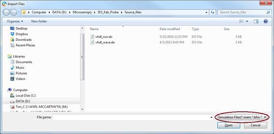
3. Import the ModelSim macro file and Wave format file.
4. Enter the following in the Import Files dialog box then click Open:
• Look in: \Microsemiprj\SF2_Fab_Probe\Source_files
• Files of type: Simulation Files (*.mem *.bfm *.dat *.txt *.do)
• File name: Hold the shift key and select vhdl_run.do and vhdl_wave.do
Page 19 of 42 v3.1SmartFusion2/IGLOO2 Fabric Lab Guide
Figure 27 - Importing the simulation files
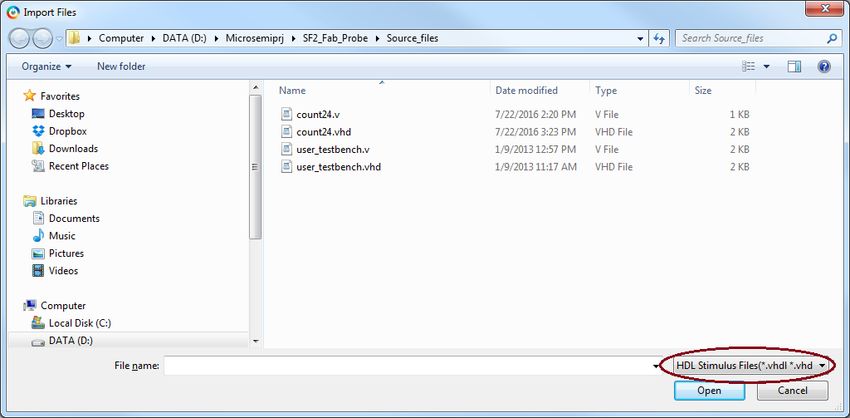
5. Import the testbench by right-clicking Simulate under Verify Pre-Synthesized Design in the Design Flow window
and selecting Import Files.
6. Enter the following in the Import Files dialog box then click Open:
• Look in: \Microsemiprj\SF2_Fab_Probe\Source_files
• Files of type: HDL Stimulus Files (*.vhd *.v )
• File name: user_testbench.vhd
Figure 28 - Importing the testbench
7. Select the Stimulus Hierarchy tab & click Build Hierarchy. The testbench (user_testbench.vhd) will be visible.
Select the testbench, right-click and select Set As Active stimulus. A waveform symbol will indicate the active
stimulus (circled below).
Note: If user_testbench.vhd is not visible on the Stimulus Hierarchy tab, the file was not imported as an HDL
stimulus file. Re-import the file as described above.
Page 20 of 42 v3.1SmartFusion2/IGLOO2 Fabric Lab Guide
Figure 29 - Testbenches in the SmartFusion2_Fabric project
The testbench and simulation files will be visible on the Libero SoC Files tab under Stimulus and Simulation.
Figure 30 - Testbench and simulation files
8. Open the ModelSim macro file (vhdl_run.do) in the Libero SoC editor by double-clicking the filename on the Files
tab.
9. Locate the variable PROJECT_DIR on line 15 of vhdl_run.do and confirm that it matches the location of your
Libero SoC fabric tutorial. The location is displayed at the top of the Libero SoC GUI (do not include
“SmartFusion2_Fabric.prjx”). Edit the path if necessary.
Figure 31 - Location of Libero SoC project
10. Locate the variable INSTALL_DIR on line 17 of vhdl_run.do and confirm that it matches the location of your
Libero SoC installation. Edit the path if necessary. Ask the lab instructor if you do not know the Libero SoC
installation path.
11. If you made changes, save the file (File > Save vhdl_run.do).
12. Scroll in the file to become familiar with the commands it contains. The command force –freeze forces some of
the counter bits in LED_ctrl high to speed up the simulation in the second phase of the simulation.
13. Close the editor (File > Close vhdl_run.do).
14. Open the Libero SoC project settings (Project > Project Settings).
Page 21 of 42 v3.1SmartFusion2/IGLOO2 Fabric Lab Guide
Figure 32 - Libero SoC Project Settings dialog box (settings for SF2PLUS-DEV-KIT board shown)
15. Select Do File under Simulation Options in the Project Settings Dialog box.
16. Un-check “Use automatic DO file”.
17. Click the browse button ( )next to “User defined DO file” and enter the following then click Open:
• Look in: \Microsemiprj\SF2_Fab_Probe\SmartFusion2_Fabric\simulation
• Files of type: *.do
• File name: vhdl_run.do
The ModelSim macro file vhdl_run.do calls the Wave format file vhdl_wave.do, so there are no settings required
for the Wave Format file.
Figure 33 - Simulation options
18. Click Save then Close to close the Project settings dialog box.
Page 22 of 42 v3.1SmartFusion2/IGLOO2 Fabric Lab Guide
19. Select Project -> Tool Profiles…
In order to use a ModelSim tool version which is supported by the Silver license, a new Simulation profile has to
be added.
Figure 34 - Tool Profiles
20. Select Simulation under Tools, click Add profile + button and enter settings below, then click OK:
• Name: ModelSim ME
• Tool integration: ModelSim
• Browse to Location and select: C:\Microsemi\Libero_SoC_v12.0\ModelSim\win32acoem\modelsim.exe
Figure 35 - ModelSim ME Profile
21. Make sure ModelSim ME is set as Active Simulation Profile, then press OK
Page 23 of 42 v3.1SmartFusion2/IGLOO2 Fabric Lab Guide
22. Expand Verify Pre-Synthesized Design in the Design Flow window. Right-click Simulate and select Open
Interactively to launch ModelSim in GUI mode.
Figure 36 - Launching pre-synthesis simulation
23. The simulation will run for 2.0 ms. When finished, the Wave window should appear as shown below after
selecting Zoom full from the popup menu (click right mouse button inside Wave – Default window).
Figure 37 - ModelSim Wave window
Page 24 of 42 v3.1SmartFusion2/IGLOO2 Fabric Lab Guide
24. Scroll in the wave window. The LED[7:0] port represents the LED driver (0 = LED off; 1 = LED on. The USER_LED
port is the re-directed Live Probe output. In the simulation this appears as a Hi-Z signal. When SmartDebug is
used, the output of any flip-flop can be re-directed to this output port.
25. Contact the lab instructor if your results do not match the figure above.
26. Close the ModelSim simulator (File > Quit). Click Yes when asked if you want to quit.
Step 3 – Editing the I/O Physical Constraint file
There are multiple ways to make I/O Assignments. In this lab we will use the I/O Physical Design Constraint (PDC) file
that was imported when the project was created. The I/O pdc file must be edited to match the target board.
1. Double-click Manage Constraints in the Libero SoC Design Flow window to open the Libero SoC Constraint
Manager.
Figure 38 - Libero SoC Constraint Manager
2. Select the Constraint Manager I/O Attributes tab. Double-click the Fabric_Top.pdc to open the file in the Libero
SoC editor. Scroll in the file to become familiar with the syntax. The constraint set_iobank sets the input voltage
of the bank to determine the allowable I/O standards; the constraint set_io sets the pin number and I/O specific
attributes. The # symbol is a comment.
Page 25 of 42 v3.1SmartFusion2/IGLOO2 Fabric Lab Guide
Figure 39 - PDC file in the Libero SoC constraint editor
A description of the Designer PDC constraints is available in the Libero Help (Help > Help Topics > Manage
Constraints > Assigning Design Constraints > Design Constraints Guide > Reference > Constraints by File Format
> PDC Command Reference).
For more information regarding pin assignments for the SmartFusion2 target board, refer to the schematic for
the board, which is available from the Trenz Electronic website (http://www.trenz-
electronic.de/fileadmin/docs/Trenz_Electronic/Modules_and_Module_Carriers/2.5x6.15/TEM0001/REV01/Docu
ments/SCH-TEM0001-01-010C.PDF).
3. All the assignments in the PDC file are commented. Uncomment the lines starting with set_iobank and set_io.
4. Save the PDC file after making modifying (File > Save Fabric_Top.pdc).
5. Close the PDC file (File > Close Fabric_Top.pdc).
6. Check Fabric_Top.pdc for Place and Route on the I/O Attributes tab of the Libero Constraint Manager.
Figure 40 - Selecting the I/O PDC constraint file in the Design Flow window
Page 26 of 42 v3.1SmartFusion2/IGLOO2 Fabric Lab Guide
Step 4 - Generating Timing Constraints
In this step you derive timing constraints for the design. Timing constraints for known blocks (such as the RC
oscillators and the PLLs) can be generated automatically.
1. Select the Timing tab in the Constraint manager window. Click on Derive Constraints.
Figure 41 - Deriving Timing Constraints
2. Click on Yes in the Message window to automatically associate the derived constraints SDC file to the ‘Synthesis’,
‘Place and Route’ and ‘Timing Verification’.
Figure 42 - Message Window
3. Double click on the Top_derived_constraints.sdc to view the automatically generated clock constraints in the
text editor.
Figure 43 - Derived Timing Constraints
4. For this design a Clock constraint and Generated Clock constraint are generated automatically. The Clock
constraint is the constraint for the 50 MHz RC oscillator, which is the reference clock for the fabric CCC. The
Generated Clock constraint is the constraint for the 1 MHz Fabric PLL output.
Figure 44 - Derived timing constraints
5. Close the Constraint Manager Editor (File > Close Top_derived_constraints.sdc).
Page 27 of 42 v3.1SmartFusion2/IGLOO2 Fabric Lab Guide
Step 5 – Synthesis and Layout
In this step you will use the push-button flow to synthesize the design with Synplify Pro, run layout and generate the
programming file.
1. Double-click the Generate Bitstream in the Design Flow window to synthesize the design, run layout using the
I/O constraints that were created and generate the programming file.
Figure 45 - Generate Bitstream
The design implementation tools will run in batch mode. Successful completion of a design step will be indicated
by a green check mark next to the Implement Design item in the Design Flow window.
Page 28 of 42 v3.1SmartFusion2/IGLOO2 Fabric Lab Guide
Figure 46 – Successful completion of design implementation
2. The Reports tab will display reports for the tools used to implement the design.
Figure 47 - Reports tab after implementing the design
Page 29 of 42 v3.1SmartFusion2/IGLOO2 Fabric Lab Guide
3. Select the Compile report (Fabric_Top_compile_netlist_resources.xml) under Synthesize on the Reports tab to
view the resource usage. Record the number of combinatorial cells (LUTs) and sequential cells (Flip-flops) used
in the design below.
LUTs (4LUT) ___________________________
Flip-flops (DFF) ___________________________
4. Generate a timing report by right-clicking Verify Timing under Verify Post Layout Implementation on the Design
Flow tab and selecting Run.
Figure 48 - Generating the post-layout timing report
5. Select the timing report named Fabric_Top_max_timing_slow_1.14V_85C.xml under Verify Timing on the
Reports tab. Scroll to the timing summary in the Report window. Record the maximum frequency for the clock
FCCC_0/ GL0 below:
FCCC_0/ GL0: ________________________
6. Timing violations can quickly be identified by looking at the timing violations reports
(Fabric_Top_max_timing_violations_slow_1.14V_85C.xml and
Fabric_Top_min_timing_violations_fast_1.26V_0C.xml).
7. The output files from Synplify Pro and Designer will be visible on the Libero SoC Files tab.
Page 30 of 42 v3.1SmartFusion2/IGLOO2 Fabric Lab Guide
Figure 49 - Synthesis and Designer files on Libero SoC Files tab
Page 31 of 42 v3.1SmartFusion2/IGLOO2 Fabric Lab Guide
Step 6 – Programming
In this step, you will run FlashPro in batch mode to program the SmartFusion2 device on the SmartFusion2 target
board. Connect the SMF2000 board using a Micro-USB cable to the PC USB port (board power is provided from PC
USB port).
1. Expand Program Design in the Design Flow window. Right-click Run PROGRAM Action and select Run to begin
programming.
Figure 50 - Launching Programming software from Design Flow window
2. FlashPro will run in batch mode and program the device. Programming messages will be visible in the Libero SoC
log window (programmer number and device number may differ).
Note: Do not interrupt the programming sequence; it may damage the device or the programmer.
3. The following message should be visible in the Reports view under Program Device when the device is
programmed successfully (programmer number will differ; device will differ depending on the target board):
programmer '30237' : device 'M2S010' : Executing action PROGRAM PASSED.
Page 32 of 42 v3.1SmartFusion2/IGLOO2 Fabric Lab Guide
Figure 51 - Programming messages in Libero SoC log window
4. A green check mark will appear next to Program Design and Run PROGRAM Action in the Design Flow window to
indicate programming completed successfully.
Figure 52 - Design Flow window after programming
Running the Application
5. Reset the board by pressing and releasing the Reset button (the button on the opposite side of the LEDs) and
observe the pattern of the LEDs.
6. Press the USER_BTN (the button near the 8 LEDs) and observe the counter changing the count direction.
Page 33 of 42 v3.1SmartFusion2/IGLOO2 Fabric Lab Guide
Step 7 - Debugging with SmartDebug
In this step you will use SmartDebug to view internal circuits in the design.
SmartDebug tool is a new approach to debug the Microsemi FPGA array and SERDES without using an internal logic
analyzer (ILA). SmartDebug provides the following methods to debug the SmartFusion2 / IGLOO2 FPGA array:
• Live Probe: Two dedicated probes can be configured to observe a Probe Point which is any input or output of a
logic element. The probe data can then be sent to an oscilloscope or logic analyzer.
• Active Probe: Active Probe allows dynamic asynchronous read and write to a flip-flop or probe point. This
enables a user to quickly observe the output of the logic internally or to quickly experiment on how the logic will
be affected by writing to a probe point.
• Memory Debug: Memory debug is used to debug embedded FPGA fabric memories (uSRAM and LSRAM) by
reading and writing to the memory block. Memory Debug also supports reading eNVM memory content.
• Probe Insertion: Probe insertion is used to insert probes into the design and bring signals out to the FPGA
package pins to evaluate and debug the design.
• SERDES Debug: SmartDebug is used to debug high speed serial interfaces by utilizing on-chip PRBS features and
signal integrity controls.
SmartDebug Live Probes
In this step we will use Live Probe A to drive one of the LEDs on the target board. The LIVE_PROBE_FB macro re-
directs the Live Probe output. For this design we connected the PROBE_A output of the LIVE_PROBE_FB macro to an
output pin which is connected to the USER_LED on the target board.
1. Expand Debug Design in the Libero Design Flow window. Select SmartDebug Design then right-click and select
Open Interactively.
Figure 53 - Launching SmartDebug
2. The SmartDebug GUI will open. Click the Debug FPGA Array button (circled in the figure below). The Debug
SERDES option may not be available for some target boards.
Page 34 of 42 v3.1SmartFusion2/IGLOO2 Fabric Lab Guide
Figure 54 - SmartDebug GUI (SF2PLUS-DEV-KIT board shown)
4. Select the Live Probes tab in the Debug FPGA Array GUI. The design hierarchy is displayed in the left window.
Signals selected for probing are displayed in the right window.
Figure 55 - SmartDebug Live Probes tab
5. Select count24_0 in the Instance Tree on the Hierarchical View then click Add. The signals will appear in the Live
Probes tab.
Page 35 of 42 v3.1SmartFusion2/IGLOO2 Fabric Lab Guide
Figure 56 - count24_0 signals in the Live Probes tab
6. Select the signal LED_c[0]:count24_0/Q_int[16]:Q then click Assign to Channel A.
7. The USER_LED starts blinking.
8. Select a different signal and assign it to Channel A. Observe the change in the LED patterns. Live Probe allows
observation of any flip-flop output without having to run layout on the design.
9. Try assigning a few other signals to Channel A and observe the results.
SmartDebug Active Probes
In this step, we will use the Active Probes to observe the output of count_24_0.
10. Select the Active Probes tab in the Debug FPGA Array GUI. The design hierarchy is displayed in the left window.
Signals selected for probing are displayed in the right window.
Page 36 of 42 v3.1SmartFusion2/IGLOO2 Fabric Lab Guide
Figure 57 - SmartDebug Active Probes tab
11. Select count24_0 in the Instance Tree on the Hierarchical View then click Add. The signals will appear in the
Active Probes tab.
Figure 58 - Adding the count24_0 signals to the Active Probes tab
12. Click the Read Active Probes button (circled in the figure below). The state of the signal will be displayed.
Clicking Read Active Probes repeatedly will allow observation of the counter output.
Page 37 of 42 v3.1SmartFusion2/IGLOO2 Fabric Lab Guide
Figure 59 - Reading the counter with the Active Probes
13. Click Close to close the Debug FPGA dialog box. Click Cancel when prompted about saving the active probes.
14. Close SmartDebug (File > Exit) and Libero SoC (Project > Exit).
End of SmartFusion2 Fabric lab
Page 38 of 42 v3.1SmartFusion2/IGLOO2 Fabric Lab Guide Record answers to questions below Name: _______________________________ Page 34 Record the number of combinatorial and sequential cells used in the design below. LUTs (4LUT) _______________________ Flip-flops (DFF) _______________________ Page 35 Record the maximum frequency for the clock FCCC_0/ GL0 below: FCCC_0/ GL0: ______________________ Page 39 of 42 v3.1
SmartFusion2/IGLOO2 Fabric Lab Guide

Answers to Questions (results can slightly vary on your system)
Page 34
Record the number of sequential and combinatorial cells used in the design below.

   4LUT         25

   DFF          24

Page 35
Record the maximum frequency for the clock FCCC_0/GL0 below:

FCCC_0/ GL0: 431.965 MHz

Page 40 of 42                                             v3.1
SmartFusion2/IGLOO2 Fabric Lab Guide

List of Figures
Figure 1 - Libero SoC Project Manager ............................................................................................................................. 5
Figure 2 - Libero SoC New Project dialog box ................................................................................................................... 6
Figure 3 - Project Details ................................................................................................................................................... 6
Figure 4 - Device selection (settings for SMF2000 board shown) .................................................................................... 7
Figure 5 - Device Settings (settings for SMF2000 board shown) ...................................................................................... 8
Figure 6 - Design Template settings (all kits) .................................................................................................................... 8
Figure 7 - Imported HDL source files................................................................................................................................. 9
Figure 8 - Imported I/O Constraint file ........................................................................................................................... 10
Figure 9 - HDL source file and I/O constraint file in Libero SoC ...................................................................................... 10
Figure 10 - Opening the SmartDesign canvas ................................................................................................................. 11
Figure 11 - Entering SmartDesign name ......................................................................................................................... 11
Figure 12 - Clock & Management category of the Libero SoC IP Catalog ....................................................................... 11
Figure 13 - Configuring the fabric CCC ............................................................................................................................ 12
Figure 14 - Configuring the Chip Oscillators (SmartFusion2 target) ............................................................................... 13
Figure 15 – Macro Library category of the Libero SoC IP Catalog................................................................................... 13
Figure 16 - IP Catalog Search field .................................................................................................................................. 14
Figure 17 - SmartDesign canvas after adding components ............................................................................................ 14
Figure 18 - Adding a slice to the Q[23:0] output............................................................................................................. 15
Figure 19 - Edit Slices dialog box ..................................................................................................................................... 16
Figure 20 - Adding a slice to the count24_0 output ....................................................................................................... 16
Figure 21 - Marking the PROBE_B port unused .............................................................................................................. 16
Figure 22 – Adding a port in Design Canvas.................................................................................................................... 17
Figure 23 – Adding LED[1:8] output port in Design Canvas ............................................................................................ 17
Figure 24 - SmartDesign canvas after making connections ............................................................................................ 17
Figure 25 - Setting Fabric_Top as the root level ............................................................................................................. 19
Figure 26 - Importing the testbench ............................................................................................................................... 19
Figure 27 - Importing the simulation files ....................................................................................................................... 20
Figure 28 - Importing the testbench ............................................................................................................................... 20
Figure 29 - Testbenches in the SmartFusion2_Fabric project ........................................................................................ 21
Figure 30 - Testbench and simulation files ..................................................................................................................... 21
Figure 31 - Location of Libero SoC project ...................................................................................................................... 21
Figure 32 - Libero SoC Project Settings dialog box (settings for SF2PLUS-DEV-KIT board shown) ................................. 22
Figure 33 - Simulation options ........................................................................................................................................ 22
Figure 34 - Tool Profiles .................................................................................................................................................. 23
Figure 35 - ModelSim ME Profile .................................................................................................................................... 23
Figure 36 - Launching pre-synthesis simulation.............................................................................................................. 24
Figure 37 - ModelSim Wave window .............................................................................................................................. 24
Figure 38 - Libero SoC Constraint Manager .................................................................................................................... 25
Figure 39 - PDC file in the Libero SoC constraint editor.................................................................................................. 26
Figure 40 - Selecting the I/O PDC constraint file in the Design Flow window ................................................................ 26
Figure 41 - Deriving Timing Constraints .......................................................................................................................... 27
Figure 42 - Message Window.......................................................................................................................................... 27
Figure 43 - Derived Timing Constraints ........................................................................................................................... 27
Figure 44 - Derived timing constraints ............................................................................................................................ 27
Figure 45 - Generate Bitstream....................................................................................................................................... 28
Figure 46 – Successful completion of design implementation ....................................................................................... 29

Page 41 of 42                                                                             v3.1
SmartFusion2/IGLOO2 Fabric Lab Guide

Figure 47 - Reports tab after implementing the design.................................................................................................. 29
Figure 48 - Generating the post-layout timing report .................................................................................................... 30
Figure 49 - Synthesis and Designer files on Libero SoC Files tab ................................................................................... 31
Figure 50 - Launching Programming software from Design Flow window ..................................................................... 32
Figure 51 - Programming messages in Libero SoC log window ...................................................................................... 33
Figure 52 - Design Flow window after programming ..................................................................................................... 33
Figure 53 - Launching SmartDebug ................................................................................................................................. 34
Figure 54 - SmartDebug GUI (SF2PLUS-DEV-KIT board shown) ...................................................................................... 35
Figure 55 - SmartDebug Live Probes tab ......................................................................................................................... 35
Figure 56 - count24_0 signals in the Live Probes tab...................................................................................................... 36
Figure 57 - SmartDebug Active Probes tab ..................................................................................................................... 37
Figure 58 - Adding the count24_0 signals to the Active Probes tab ............................................................................... 37
Figure 59 - Reading the counter with the Active Probes ................................................................................................ 38

Page 42 of 42                                                                       v3.1
You can also read