DEHUMIDIFIERS - INSTALLATION MANUAL DS SERIES LD/LEEDER SERIES - DEHUMIDIFIED AIR ...
←
→
Page content transcription
If your browser does not render page correctly, please read the page content below
DEHUMIDIFIERS
 DS Series    LD/LEEDeR Series

INSTALLATION MANUAL

Dectron.com
Dectron Dehumidifier Install Manual 2 January, 2021
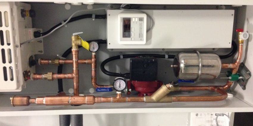
Table of Contents
General Information .......................................................................................................................................... 4
   Operating Safety (Warnings, Cautions, and Notes) ................................................................................................... 4
   Reference and Additional Information ...................................................................................................................... 5
Delivery and Storage. ......................................................................................................................................... 6
   Receiving Checklist .................................................................................................................................................... 6
   Shipping Damage Handling ........................................................................................................................................ 6
   Storage....................................................................................................................................................................... 7
Mechanical Installation ...................................................................................................................................... 8
   Lifting and Rigging ..................................................................................................................................................... 8
   General Mechanical Installation Requirements ........................................................................................................ 9
   General Placement of the Equipment ....................................................................................................................... 9
   Outdoor Condenser (OACC) and Fluid Cooler (OAFC) Mechanical Installation ....................................................... 12
   Mechanical Installation – Special Cases................................................................................................................... 15
Ductwork Connection ....................................................................................................................................... 18
   Ductwork Layout Considerations............................................................................................................................. 18
   Duct Connection – General Considerations............................................................................................................. 18
   Duct Connection – Special Cases ............................................................................................................................. 19
Piping Connection ............................................................................................................................................. 20
   Piping Connection General Considerations ............................................................................................................. 20
   Condensate Drain Connection and P-trap Installation ............................................................................................ 20
   Pool Water Heating Piping....................................................................................................................................... 21
   Outdoor Air Condenser Piping (NC models) ............................................................................................................ 22
   Fluid Cooler Piping (NG models) .............................................................................................................................. 24
   Other Piping Systems and Special Cases.................................................................................................................. 26
Electric Connection: power, control and communication ................................................................................... 28
   Electrical Connection - General Considerations ...................................................................................................... 28
   Equipment Main Power Connection........................................................................................................................ 28
   Outdoor Air Condenser and Fluid Cooler Power and Control Connection .............................................................. 29
   Field Wiring – External Control and Communication .............................................................................................. 29
   Field Wiring – Special Cases..................................................................................................................................... 33

January, 2021                                                                           3                               Dectron Dehumidifier Install Manual
General Information
This manual provides basic information about various installation aspects of the applicable equipment and its
additional and auxiliary systems and devices.

    •   This manual covers installation details of the equipment of various design, size, capacity etc.; therefore,
        some details covered in this manual may not be relevant to each piece of equipment. Refer to your
        equipment’s submittal documentation.

Important information regarding operation, maintenance, and start up is normally provided with the equipment
and can also be obtained from the manufacturer – contact Customer Support Team as needed (see Reference and
Additional Information on the following page).

Operating Safety (Warnings, Cautions, and Notes)
FOR YOUR SAFETY: READ BEFORE PERFORMING ANY INSTALLATION OR OTHER TASKS!

                 Only qualified technicians should install, operate, maintain or service mechanical equipment
                 including this dehumidification system.
                 Make sure to read this manual before performing any installation tasks to familiarize yourself
                 with the equipment as well as with any potential hazards. Always exercise caution!

                                            Beware of high pressures and chemicals!
                 •    Dehumidifiers, equipped with compressors, contain refrigerant under high pressure; oil is
                      also contained in the compressor and refrigeration circuit(s)
                 •    Some dehumidifiers may also contain other liquids such as glycol mixtures and pool water

The following warnings, cautions, and notes appear throughout this manual and referenced documentation
whenever special care must be taken to avoid potential hazards that could result in equipment malfunction or
damage, personal injury, or death.

      WARNING                                 CAUTION                           Note
Indicates a potentially hazardous       Indicates a potentially hazardous       Indicates a situation that could
situation which could result in         situation which could result in         result in equipment damage or
serious injury or death if handled      moderate injury or equipment            improper/ineffective operation if
improperly.                             damage if handled improperly.           handled improperly.

Dectron Dehumidifier Install Manual                      4                                             January, 2021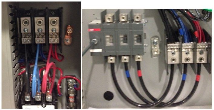
Reference and Additional Information
For safe, efficient and problem-free operation, it is critical to handle the dehumidifier (as well as related systems
and components) properly at each step - from receiving and storage to installation and start up. Relevant
information can be found in the respective documents (Operation and Maintenance Manual, Start Up Package,
etc.) provided with the dehumidifier. This manual as well as other related documents can be obtained from the
manufacturer (see Contact Us below).

Warranty
The manufacturer standard warranty statement can be found in the Operation and Maintenance Manual,
provided with the equipment.
                              Attention: Warranty Conditions and Coverage.
NOTE. The equipment is provided with comprehensive conditional warranty coverage. Any warranty work to be
reimbursed must be approved by Service & Customer Support Team prior to work commencing. Installation,
start up, maintenance etc. are not within warranty scope. Refer to the manufacturer standard warranty
statement for more details on warranty conditions, scope and coverage.

                                    Attention: Equipment Proper Usage.

       CAUTION! Dehumidifier is NOT intended, and, therefore, NOT to be used, to condition (heat, cool,
ventilate etc.) premise that is still under construction. Such usage may cause equipment premature wear, poor
performance and potential failure afterwards and will void the warranty!

      WARNING! Any work (installation, start up, service, maintenance, repair, etc.) on any mechanical
equipment (dehumidifier, outdoor condenser, fluid cooler, etc.) must be performed in accordance with
respective manufacturer recommendations as well as submittal documentation, local Codes and Regulations, and
appropriate field practices. Failure to do so could result in personal injury, equipment damage or malfunction,
and will void equipment warranty. Only qualified and properly trained individuals should perform tasks on this
equipment.

Contact Us
 Dectron                                 1-833-DAS-POOL (327-7665)
 5685 Rue Cypihot
 Saint Laurent QC, H4S1R3                Schedule / Modify a Start-up:
 Canada                                           Startups@DehumidifiedAirServices.com
                                         Inquire about Warranty:
 Dectron.com                                      Warranty@DehumidifiedAirServices.com
                                         Order Parts:
                                                  Parts@DehumidifiedAirServices.com
                                         All Other Product Support:
                                                  Support@DehumidifiedAirServices.com

January, 2021                                              5                     Dectron Dehumidifier Install Manual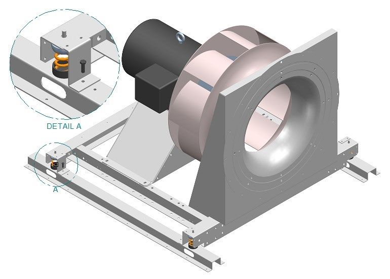
Delivery and Storage.
Receiving Checklist
Each piece of equipment is tested and inspected before it ships from the factory; however, the equipment may
suffer damage in transit.
It is highly recommended to thoroughly check for both visible and concealed damage upon the equipment arrival
and before signing the receiving papers:
Visually inspect exterior of the equipment for damages (scratches, dents, missing elements, etc.)
Verify the proper operation of latches and hinges on all access doors
Inspect all coils for damage to the fin surface coating, headers or coil connections
Manually rotate the fan wheel to ensure free movement of the shaft, bearings, and drive
Inspect the fan housings for any foreign objects
Inspect and test all piping for possible shipping damage
Check the tightness of bolts on the fan structure and coils
Inspect fan isolator shipping brackets
Shipping Damage Handling
Default manufacturer shipping method is “freight on board” (FOB), meaning that the equipment belongs to the
customer as soon as the delivery truck leaves the factory.
Note: Manufacturer is not responsible for any shipping damage. Should the equipment arrive damaged,
follow the instructions below to resolve the situation. Delivery cannot be refused on the basis of shipping
Shipping Damage Handling Instructions:
Note the damage in detail on the freight bill and bill of lading.
Take clear photographs of the damaged components, areas, and portions of the equipment.
Obtain a claim form from the carrier, fill it out, and return it promptly. Report all claims of shipping damage to
the carrier immediately and coordinate a carrier inspection if necessary.
Contact Customer Support Team (see Contact Us above) to notify of the noted damage.
o Have the equipment serial number (8-digit) on hand to provide to Customer Support Team. The serial
number can be found on the equipment’s main label or bill of lading.
o Note: it is the receiver's responsibility to provide reasonable evidence that damage was not incurred
after delivery.
o Do not attempt to repair the equipment without consulting with Customer Support Team.
Dectron Dehumidifier Install Manual 6 January, 2021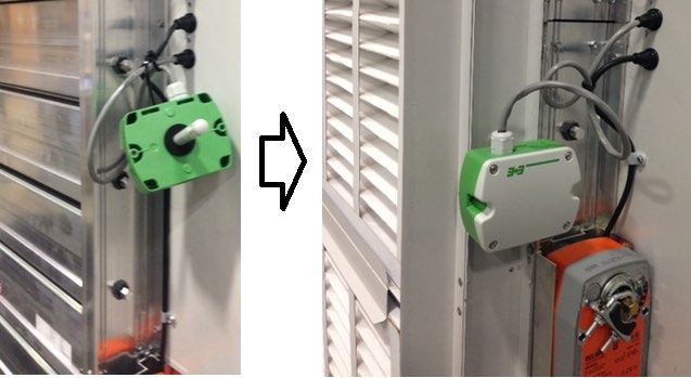
Storage
•   Protection from the elements is required for any equipment that will be stored on a job site or holding area
    before installation.
•   For long-term storage, a controlled indoor environment is highly recommended.
•   All factory-applied shipping protection should be removed before the equipment is put into storage. Shipping
    protection material is provided by the factory for shipping only – it is not a suitable protection for short or
    long-term storage.
•   If long-term storage is required, warranty aspect should be considered - refer to the Warranty section of
    Operation and Maintenance Manual for more details regarding standard warranty terms and conditions.
    Contact manufacturer if needed.

January, 2021                                            7                    Dectron Dehumidifier Install Manual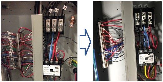
Mechanical Installation
WARNING! All work must be done by qualified personnel in accordance with local and national Codes,
Standards and Regulations as well as respective submittal documentation and manufacturer recommendations.
CAUTION! Obtain all necessary documentation (manufacturer documentation, submittal documentation,
drawings, etc.) and familiarise yourself with it before performing installation or any other related tasks.
Lifting and Rigging
WARNING! Lifting and rigging must be done by trained professionals in accordance with proper lifting
techniques and safety procedures. Proper lifting machinery and tools and safety equipment (PPE) must be used.
Improper lifting may cause equipment damage, serious injury, or death. Manufacturer is not responsible for the
improper use of lifting equipment.
Use spreader bars for lifting to prevent equipment damage. Use cables (chains or slings) as shown on Pic. E.1.
o Use dehumidifier lifting brackets at
the base frame.
Each of the lifting cables (chains or slings)
must be capable to support the entire
weight of the equipment.
Determine the approximate centre of
gravity before lifting. See equipment design
drawings in the submittal documents for the
total weight and weight distribution.
Lifting cables (chains or slings) may not be of
the same length. Adjust as necessary for an
even lift.
Do not lift equipment in windy conditions.
Do not raise equipment overhead with
personnel below.
Test lift the equipment 24 inches to verify
proper operation of lifting machinery and Pic. E.1
positioning of lift points such that the lifted equipment is level.
To avoid damage, do not attach intake or exhaust hoods prior to lifting
“Split-Cut” Dehumidifier Lifting
Some dehumidifiers may, if requested, be shipped in sections to be assembled on site.
Never assemble split sections before lifting them to the installation location.
o Always lift sections separately, as received from the factory.
Lift each section using its lifting lugs/brackets.
Dectron Dehumidifier Install Manual 8 January, 2021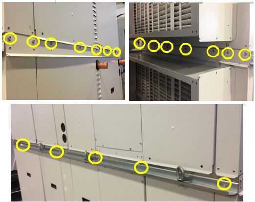
General Mechanical Installation Requirements
Equipment (dehumidifier, outdoor condenser, fluid cooler, etc.) should be installed in accordance with respective local Codes and
Regulations as well as applicable submittal documentation. There are several general key installation points:
General Placement of the Equipment
Equipment must be installed on a firm, levelled surface, with provision for vibration absorption.
Service and operational clearances to the equipment must be always maintained.
o Access to ALL doors, louvers, filter racks, access ports and covers must not be restricted. Some
installations may require cat-walks (over ducts, pipes, etc.) or other means of access to otherwise
restricted side of the equipment.
o Dehumidifier: may require up to 36” clearance for proper operation, service and maintenance;
o Outdoor Condenser (OACC)/Fluid Cooler (OAFC): may require up to 36” clearance all around and up
to 96” clearance above fan for proper operation, service, and maintenance.
Avoid installing OACC/OAFC in a pit, where it’s surrounded on all four sides by walls,
structures, etc. If such an installation cannot be avoided, the following must be maintained:
• the min. clearances must be increased to double width of the OACC/OAFC all around;
• surrounding structures’ height must not exceed the height of the OACC/OAFC.
NOTE. For equipment-specific data (dimensions, clearances, accessibility, etc.) refer to equipment submittal
documentation, Operation and Maintenance Manual, and equipment labels and stickers.
Indoor Dehumidifier Installation (dehumidifier, installed in mechanical room)
No chemicals allowed to be stored in the same mechanical room;
o other stored materials must not block access to the equipment for service and maintenance.
Mechanical room must have operational floor drain.
Ceiling-suspended installation: support dehumidifier from (underneath) the base; refer to submittal
documentation for dehumidifier weight distribution for proper selection and positioning of support.
Outdoor Air (OA) intake box. Some dehumidifiers with outdoor intake option, may have an OA intake box,
mounted onto the OA intake opening or provided separately to be field-installed. If latter is the case:
o install box over the OA opening, attach it to the dehumidifier with provided self-tapping screws.
o Attach OA duct to the box (see Ductwork
Connection chapter). Junction box
o Control/electrical contractor: connect
control wire harness to the OA box devices
(actuators, sensor etc.) inside the junction
box (see Pic. E.2) – follow the junction box
legend and dehumidifier wiring diagram. Pic. E.2
Outdoor Dehumidifier Installation
Roof Curb. If the dehumidifier is installed on a roof curb, it must utilize curb gasket material (to create a
moisture and weather seal between the dehumidifier and a roof curb).
o ATTENTION! Before placing onto a roof curb, consider accessibility underneath the dehumidifier for
various mechanical and electrical systems connections (power, drain, other piping, etc.)
o ATTENTION! It is not recommended to use space within a roof curb as a supply or return duct.
Consider the direction of strong prevailing winds – it may negatively affect equipment operation (cross-flow of
exhausted and fresh air and/or flue gases, elements (rain, snow) aspiration into the OA opening, etc.)
January, 2021 9 Dectron Dehumidifier Install Manual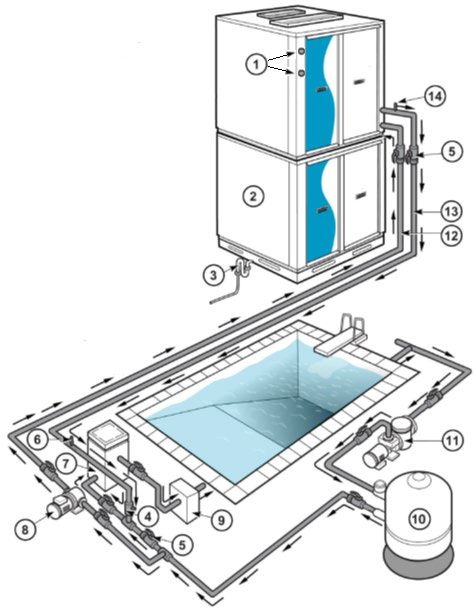
Outdoor Dehumidifier – Louvers Installation
To protect outdoor-installed dehumidifier openings (outdoor air intake, exhaust air discharge, etc.) against
elements, louvers are installed or provided separately for field installation. If latter is the case:
Uncrate/unwrap provided louver and place it over respective opening/damper (Pic. E.3):
o Larger louvers require two persons to lift and place the louver
o Dehumidifier with larger louvers also have louver support lip over the damper.
Adjust louver position – shift it slightly left or right as needed to ensure louver side walls and access panels do
not interfere with damper linkage, actuators, filter racks, sensors, etc.
Once the louver is positioned properly, attach it to the dehumidifier with the provided self-tapping screws on
all four sides. If access panels were removed for louver installation, reattach the panels and close the latch.
Support lip Cover panel
Pic. E.3
Outdoor AND Indoor Dehumidifier - Field-installed OA (outdoor air intake) Filter Rack Installation
If the Outdoor Air intake (OA) filter rack is shipped separately, it should be attached to respective opening/damper
once dehumidifier is installed. This may apply to both, indoor and outdoor installed dehumidifiers.
Attach filter rack to the damper with provided self-tapping screws; position rack as shown on Pic. E.4.
Once the rack is installed, insert/install OA sensor (thermistor or combo sensor, as shown in the picture)
between the damper and the filters; ensure that the sensor will not interfere with the damper blades motion.
OA sensor
Pic. E.4
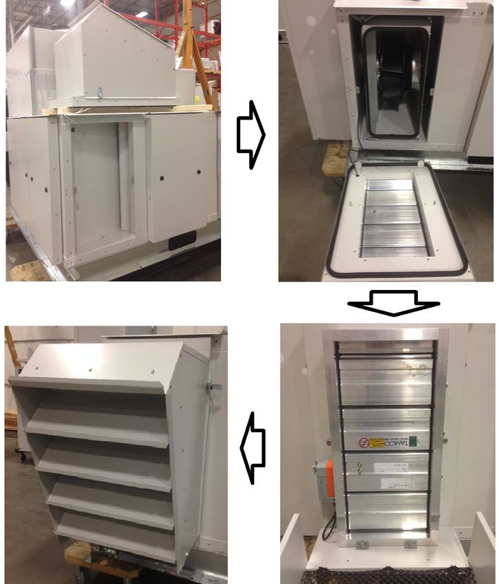
Dectron Dehumidifier Install Manual 10 January, 2021Outdoor Dehumidifier – Outdoor Air and Exhaust “Door/Louver” Assembly Installation
For shipping purposes, the OA and Exhaust Louver(s) may be shipped on the top of the dehumidifier and will
require field installation (see Pic. E.5). This normally applies to outdoor DS020-DS040 series dehumidifiers.
Remove the door/louver assembly (a) from the roof and place it in front of the respective opening; normally,
the air damper with pre-wired actuator is mounted within the louver – use caution not to damage wiring.
o The OA door/louver assembly is normally placed on the roof near/above OA opening. The Exhaust
door/louver assembly, respectively – near/above Exhaust opening.
Release louver latches (b) on both sides to open the louver and access bolts (c) later;
Place door support brackets (d) on the dehumidifier floor into the opening,
Lift the door and place it, then tighten bolts (c) to secure the door.
o OA damper would also have a filter rack, attached to it.
Lift the hood in place and lock the latches (b).
(a)
(d)
(b)
(c)
Pic. E.5
January, 2021 11 Dectron Dehumidifier Install ManualOutdoor Condenser (OACC) and Fluid Cooler (OAFC) Mechanical Installation
The requirements outlined in General Placement of the Equipment (see above) apply to all models of OACC/OAFC.
It is recommended to anchor light-weighted OACC/OAFC to the horizontal mounted surface (concrete pad etc.).
This applies to all OACC models and some OAFC models (NG-Z and NG-V-01, -02, -11 and -12).
NOTE. Do NOT exceed distance limitation between the dehumidifier and OACC or OAFC – it may result in
equipment incorrect operation and/or failure. Before finalizing OACC or OAFC placement/location, refer to
respective dehumidifier main label, as well as submittal documentation and Fluid Cooler Piping and Outdoor
Condenser Piping chapters of current manual (see further). Contact the factory if needed.
Outdoor Condensers and Fluid Coolers Field Assembly – models NC-Z, NC-B and NG-Z.
The NC-Z and NC-B Series outdoor condensers can be provided in vertical or horizontal airflow configuration and
may require field assembly of respective mounting support:
Vertical airflow configuration (equipment is mounted on a horizontal surface such as ground, roof, etc.):
OACC model NC-Z and OAFC model NG-Z assembly is shown on Pic. E.7A below:
o Uncrate/unwrap the equipment and legs.
o Install the four provided legs (a) onto the equipment (leg is to be placed inside in the corner)
Double condenser/cooler (b) would have six legs provided – place two additional legs in the
middle – refer to picture.
o Align all four holes in each leg and equipment corner and attach legs with provided bolts, washers (legs
have factory-installed nut-certs); tighten all bolts.
o Ensure that the equipment is levelled and firm; affix the legs to the surface (concrete slab, etc.);
anchors/fasteners for surface mounting are NOT included.
Pic. E.7A
Dectron Dehumidifier Install Manual 12 January, 2021 OACC model NC-B assembly is shown on Pic. E.7B below:
o Uncrate/unwrap the condenser and mounting kit.
o Assemble left and right mount legs as shown with provided bolts, nuts, and washers (except for joint
point (a) – it must be bolted to the condenser)
o Align holes (a) and (b) in the mount legs with the holes in the condenser and attach them with provided
bolts, nuts and washers.
o Attach rear support braces to the condenser with provided self-tapping screws (c)
o Install the optional front cross piece (d) between left and right leg with provided bolts, nuts and
washers;
o Ensure that the assembly is straight, square and sturdy; tighten all bolts.
o Ensure that the condenser is levelled and firm; affix mount legs footings to the surface (concrete slab,
etc.); anchors/fasteners for surface mounting are NOT included.
Pic. E.7B
Horizontal airflow configuration (equipment is mounted on a vertical surface such as a wall.). In this case, use the
same mount kit as above. Note that the mount legs are assembled slightly differently.
OACC model NC-Z and NC-B assembly is shown on Pic. E.7C below:
o Uncrate/unwrap the equipment and mounting kit.
o Assemble left and right mount legs as shown with provided bolts, nuts, and washers (except for joint
point (a) – it must be bolted to the condenser/cooler)
Note that the cross-piece (b), that is to be attached to the equipment, is mounted differently
for NC-Z and NC-B.
o Before final assembly of equipment and mount legs, ensure following:
For Outdoor Condenser NC-B: electric box is positioned as shown – horizontal, with drip
protection bend (c) at the top;
For all Outdoor Condensers (NC-Z and NC-B): refrigerant connections are on the side AND
liquid line connection (refer to condenser labels) is the bottom one, (e).
o Align respective holes in cross-piece (b) and the holes in the equipment and attach them with provided
bolts, nuts, and washers.
o Attach rear support braces to the condenser with provided self-tapping screws (d)
o Ensure that the assembly is straight, square, and sturdy; tighten all bolts.
o Ensure that the condenser is levelled and firm; affix mount legs footings to the surface (wall, etc.);
anchors/fasteners for surface mounting are NOT included.
January, 2021 13 Dectron Dehumidifier Install ManualNC-Z
Pic. E.7C
ATTENTION! Cooling Fluid Lines Sweating!
Under certain conditions (namely – when the cooling fluid lines’ outer surface drops below dew point of the
surrounding air, particularly inside the facility), said lines may “sweat” as condensation forms on their surface.
Should this occur, it is recommended to insulate the piping to prevent condensation.
Dectron Dehumidifier Install Manual 14 January, 2021Mechanical Installation – Special Cases
Some equipment may have additional/optional arrangements – refer to submittal documentation and equipment
accompanying factory instructions.
Frame-mounted main blower shipping brackets.
For shipping purposes, larger (7 HP and up) direct-driven main blower frame springs are affixed with shipping
brackets (see Pic. E.8). This normally applies to NP series dehumidifiers only.
Upon installation remove ONLY lower bolt from all four corners (detail A) at the frame base - removing these
bolts ensures that the blower vibration is dampened correctly.
If the blower frame includes two blowers (stack), in addition to
base bolts removal (described above) remove ONE bolt from
each bracket at the wall springs (B).
(B)
Pic. E.8
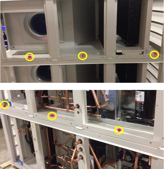
January, 2021 15 Dectron Dehumidifier Install Manual“Split-Deck” dehumidifier (“Double-Decker”) – mechanical field disassembly and assembly
If requested, “Double-decker” (stacked)
dehumidifiers are provided with means for site
disassembly (splitting top deck from the bottom
for shipping/delivery purposes) and assembly
afterwards. Refer to Disassembly and assembly
Instructions, provided with the dehumidifier!
CAUTION!
(b)
Before removing top deck from the bottom,
ensure that ALL other system connections
(piping, wiring, etc.) are disassembled.
Normally, there are two ways the top deck is
attached to the bottom (refer to the one
pertaining to your dehumidifier):
DS02D – DS15D indoor models: decks
attached with six to eight screws through
(a)
the top deck floor & bottom deck roof (see
Pic. E.9a):
o locate the plastic covers/plugs at the front (a) and back (b) of the dehumidifier and pop Pic. E.9a
them open to access screws;
o remove all the screws and lift the top deck.
o Once decks reassembled, reinstall removed screws and reinstall plastic covers.
DS08D – DS15D indoor/outdoor
models: decks attached with side
joining and lifting strips (see Pic.
E.9b):
o Locate and remove all
screws on joining strips
between the top and
bottom decks - on the (a) (b)
front (a) and back (b)
joining strips and on the
lifting bracket strips (c) on
the sides of the
dehumidifier.
o Once the dehumidifier is
installed and decks are
reassembled, make sure
to reinstall the removed (c)
screws again.
o Remove as needed the lifting eye-hooks to allow for doors removal. Pic. E.9b
Make sure to also reassemble the other system connections (piping, wiring, etc.). Refer to respective chapters.
Dectron Dehumidifier Install Manual 16 January, 2021“Split-Cut” dehumidifier – mechanical field assembly
Under special conditions, the dehumidifier may be split into two or more sections to ease the installation and
delivery process. Refer to the dehumidifier submittal drawings and Disassembly and Assembly Instructions,
provided with the dehumidifier (instructions include mechanical, piping, and electrical guidance for reassembly).
WARNING! DO NOT lift assembled dehumidifier. Lift each section separately and assemble once all
sections are placed where intended.
Place and align dehumidifier sections properly:
o To aid with proper placement, sections normally are labeled with sequential numbers (“1”, “2” etc.) –
ensure that each pair of adjacent sections at the split have same number (see Pic. E.10a).
o Before final assembly of sections – ensure piping proper alignment; plan for pipe joining.
Join sections with provided fasteners.
o Base angles (outside – see
Pic. E.10. b) are normally
bolted together with 3/8”
bolts and internal (walls,
floor, ceiling) angle (inside
– see Pic. E.10 c) are
normally attached with
5/16” bolts.
o Internal angles shape may Pic.E.10a
vary depending on
dehumidifier cabinet type.
o Ensure that all provided holes are used.
Install provided roof rib cap (see Pic. E.10 d) over each jointed roof rib and
attach it with screws; caulk the inner corner of roof rib cap prior.
Caulk all the joints (roof, floor, walls) after reassembly.
Pic.E.10b
Pic.E.10d Pic.E.10c
January, 2021 17 Dectron Dehumidifier Install ManualDuctwork Connection
WARNING! All work must be done by qualified personnel in accordance with local and national Codes,
Standards and Regulations as well as respective submittal documentation and manufacturer recommendations.
CAUTION! Obtain all necessary documentation (manufacturer documentation, submittal documentation,
drawings etc.) and familiarise yourself with it before performing installation or any other related tasks.
Refer to dehumidifier submittal drawings for location and size of dehumidifier duct connections.
Ductwork Layout Considerations
Though ductwork layout is outside of scope of dehumidifier installation and duct connection to it, it is crucial to
have proper ductwork layout for proper air distribution throughout the premise and proper dehumidifier
operation. Proper ductwork layout encompasses, among others, following:
Supply air must be directed/properly distributed to:
o exterior windows and doors, skylights, etc.
o breathing zone at the deck level and water surface.
o remainder of the room to ensure there are no stagnant areas.
Return duct grille must be located where it will optimize the entire airflow pattern (central/equidistant
location of return grille, multiple return grilles if needed, etc.).
Air short-circuiting must be prevented – no supply air diffusers near the return.
Ensure grilles, diffusers and registers are delivering proper throw distance and CFM.
Maintain the required minimum OA intake along with negative pressure in the space (respective Exhaust Fan
and OA intake arrangement)
Where/if applicable, establish direct exhaust of humid/chemical laden air from the source (locate exhaust
grille above/close to spa, whirlpool, etc.).
Duct sock installation: sock must be levelled (hangers are at the same heights), stretched and not sagging.
Duct Connection – General Considerations
All duct connections should be done in accordance with local and national standards.
o Proper duct turns and transitions (sizing, distance, angles, turn vanes, etc.) should be used to minimize air
friction losses and turbulence and to ensure the highest fan efficiency.
o If space heater (electric heater, hot water coil or gas duct heater) is installed at the dehumidifier
supply air termination, heater becomes a point for the supply duct connection – ensure proper
duct transition, support, etc. is in place – refer to heater manufacturer guidance as needed.
o Flexible connectors (canvas collars, etc.) should be used to prevent (reduce) vibration and sound
propagation.
Ductwork should not interfere with other devices/systems operation and accessibility:
o fasteners (screws, etc.) attaching ducts to the damper, are not interfering with damper linkage,
actuator(s) wiring and mounting brackets etc.
o fasteners (screws etc.) are not interfering/penetrating any internal wiring, piping etc. possibly located
behind the surface(s) ductwork is attached to – verify visually before installation and after.
o damper actuator(s), filter racks, etc. are accessible/not blocked by the installed ductwork.
Dectron Dehumidifier Install Manual 18 January, 2021Duct Connection – Special Cases
Supply Air ductwork connection – SA Temperature Sensor installation.
Some dehumidifiers may require SA (supply air) temperature sensor to be installed in the duct after duct is
connected.
In this case dehumidifier SA temperature sensor,
tagged “SUPPLY AIR TEMP SENSOR TO BE
INSTALLED IN DUCT” (see Pic. F.1), would be
attached to the side or roof of the dehumidifier -
such sensor is pre-wired to the dehumidifier
control board at the factory and needs to be
installed in supply ductwork.
• Install sensor at least 2’- 4’ downstream
of the dehumidifier or externally
mounted space heater (if one is
controlled by the dehumidifier) in the
middle of the width of the duct.
Pic.F.1
Field-installed duct-mounted space heater.
If space heater (gas duct heater, hot water or steam coil, electric heater, etc.) is not packaged with the
dehumidifier and to be installed in the duct on site:
follow said space heater manufacturer installation instructions (duct transitions, distances, clearances,
support, direction, etc.), respective local codes and regulations and standard field practices.
Install space heater in the supply duct, downstream of the dehumidifier.
It is recommended for the space heater to be controlled by the dehumidifier control system (for efficient
operation and air temperature maintenance).
Gas-fired duct heater. Indoor-installed gas heater requires respective venting to be installed. Follow the
heater manufacturer recommendation and respective local codes to select and install the venting system.
January, 2021 19 Dectron Dehumidifier Install ManualPiping Connection
WARNING! All work must be done by qualified personnel in accordance with local and national Codes,
Standards and Regulations as well as respective submittal documentation and manufacturer recommendations.
CAUTION! When connecting the equipment to external mechanical and electrical systems, refer to
submittal documentation and equipment labels and stickers for piping connection details.
Piping Connection General Considerations
Refer to the equipment main label and stickers at lines/piping termination to verify respective connecting
lines’ sizes, flow directions (IN/OUT) and system type (pool heating, space heating, etc.).
o Flow direction stickers at respective piping stubs refer to the equipment it’s attached to: IN – media
(water, refrigerant, etc.) entering the equipment, OUT – leaving the equipment.
o Select the line/piping size based on the equipment documentation (labels, drawings, etc.): diameters
of the dehumidifier or OACC/OAFC piping stubs may be different from the required line size.
Use proper materials and pipe joining methods, respective to given system (system media, pressure, etc.).
Use proper installation field practices and Code(s) requirements (proper piping support, no pipe-to-edge
contact, grounding/bonding, insulation, pressure testing, charging/filling, etc.)
As/where needed, ensure that proper isolation and balancing means (valves, circuit setters, etc.) are in place.
For water or water/glycol systems (pool water, space heating or cooling water, etc.) - provide proper means
for priming (filling), draining and aerating (bleeding the air from the system): install automatic air bleeding
valve(s) at each local top point of the system and drain/priming valves at the lowest point(s) of the system.
Condensate Drain Connection and P-trap Installation
Each dehumidifier drain pan condensate line must be directed to an external drain and equipped with a P-trap to
ensure proper drainage.
o If gravity disposal of condensate is not possible, use a condensate pump.
o If the drain line passes through an unconditioned/not-heated space, heat tracing is required to prevent the
condensate in the drain from freezing.
Dehumidifier condensate termination(s) (or it’s location) is normally marked with respective label, stating whether
given line is already equipped with a P-trap from the factory or not. If not, install a P-trap
P-trap installation:
o Make sure that each drain connection has a P-trap
o Make sure that there is only one P-trap installed (do not
double-trap).
o If soft piping material is used (braided hose, etc.)
- ensure the drain line is not sagging (this may
create “double-trapping effect” and prevent
condensate from proper drainage).
o Pitch the condensate drain line minimum of 1/8” per
linear foot and support the pipe with code-approved Pic.G.1
hangers at least every 5 feet (see Pic. G.1).
Dectron Dehumidifier Install Manual 20 January, 2021Pool Water Heating Piping
If the dehumidifier is equipped with a pool water heater (to
utilize compressor-generated heat for pool water heating), it
would require pool water piping connected to respective
dehumidifier pipe terminations.
Pic. G.2 shows an example of a generic pool water piping
schematic.
NOTE: this schematic is an example only - design, provision and
installation of actual pool water piping is not manufacturer
responsibility and is to be done by a third party.
1 OACC/OAFC connections
2 Dehumidifier
3 P-Trap/condensate line
4 Check Valve
5 Ball valve(s)
6 Flow Meter
7 Auxiliary Pool Heater
8 Aux. Pump (lowest point)
9 Automatic Chemical Feeder
10 Pool Filter
11 Main Pool Pump
12 Pool Water Inlet (IN)
13 Pool Water Outlet (OUT)
14 Air Vent
Pool Water Piping Pic.G.2
Connections – General Considerations
As shown on Pic. G.2, the chemical feeder must be located downstream of (after) the dehumidifier to prevent
the pool water heat exchanger from being exposed to high chemical concentration.
Auxilliary pump or main pool pump must be located upstream of (before) the dehumidifier.
o The dehumidifier normally requires constant waterflow through (to ensure proper automatic control
over pool heating feature); however, if requested, it could be equipped with means to control
auxiliary pump. This set up would also require a pool water temperature sensor to be installed in the
external pool water manifold/piping. Contact the factory if needed.
Proper waterflow direction (refer to the dehumidifier piping termination stickers – Pool IN/Pool OUT), rate,
GPM, and line set size (refer to dehumidifier Main Lable) must be maintained for proper and troublefree
operation.
o It is recommended to have means to adjust/balance waterflow (circuit setters, etc.)
o Some dehumidifiers can be equipped with “full flow” heat exchangers (allowing for full volume of
pool water flow) – refer to the main label info (pool water GPM).
January, 2021 21 Dectron Dehumidifier Install ManualOutdoor Air Condenser Piping (NC models)
Current sub-chapter applies to outdoor condensers NC models, serving DS series dehumidifiers.
Line Set Selection and Sizing
• Refer to dehumidifier and/or condenser main labels for line set sizing (both, max line set length and pipes’
diameters):
o note that line set pipe diameters may differ from respective piping connections size at the dehumidifier
and condenser – refer to the equipment’s main label.
o one-way line set length (liquid OR hot gas line length) must not exceed max line set length, indicated
on the main label (typically – 50’).
Note: Do NOT exceed max line set length stated on the equipment’s main label. Excessive line set length could
result in equipment malfunction and premature failure. Do NOT increase lines diameters (oversizing line set) to
compensate for excessive line set length – consult the factory first.
• The outdoor air condenser, in general, can be located above, below or at the same level as the dehumidifier,
however some limitation may apply:
o Consult the factory if the condenser is to be located 20’or more below the dehumidifier.
• Standard recommended pipe and fitting materials are refrigeration grade copper piping/tubing – refer to
material applicability according to given application (refrigerant type, max working pressure, etc.).
Piping
Ensure proper piping support and bracing is in place – condenser and dehumidifier pipe terminations do not
provide structural support for pipe line set.
Proper piping practices (cleaning, sanding, reaming, wet-ragging during brazing, etc.), tools (pipe cutters,
torches, etc.) and bonding methods, respective to pipe and fittings material must be followed/used.
o Refrigeration piping/tubing must be brazed using respective brazing equipment and materials (flux, Sil-
Fos® 5 brazing rod/wire or better etc.)
o Where applicable, only refrigerant-approved lubricant/sealant in threaded connections should be
used.
o Purge the air from the line set and condenser with nitrogen prior to brazing to avoid soot built-up inside
the lines – soot/debris may potentially plug refrigeration circuit devices and cause failure.
Identify correct system pipe terminations on condenser and dehumidifier (typically labeled as “HG/hot gas” and
“LQ/liquid”). Connect similarly labeled terminations (HG to HG, LQ to LQ).
If the condenser is installed above the dehumidifier, install an oil trap at the start of and at every 15’ of
vertical lift in the hot gas line as shown on Pic. G.4.
Pitch the horizontal lines a min ½” every 5’ in the direction of flow.
Keep the hot gas and liquid lines a min of 2” apart to prevent heat transfer. Insulate the hot gas line where a
person may come in contact with the line and be in danger of burning themselves.
CAUTION! The dehumidifier typically is shipped pre-charged with refrigerant. Before cutting dehumidifier’ pipe
stubs off to connect line set - ensure that dehumidifier isolating hot gas and liquid ball valves are closed.
o Isolating ball valves typically have access ports that could be used for nitrogen purging, pressure
testing, evacuating and charging. Check access ports for any pressure in the pipe stubs before cutting.
o Add access port(s) to the line set or at the condenser, if needed.
NOTE: The piping schematics shown on Pic. G.4, are example only - the design, provision, and installation of
actual condenser line set is not manufacturer responsibility and is to be done by a third party.
Dectron Dehumidifier Install Manual 22 January, 2021Pressure Testing, Evacuating and Charging
• Use proper field practices when pressure testing, evacuating, and charging the system.
• Pressure-test line set and condenser – refer to the dehumidifier main label for operating pressure level.
o Use only dry nitrogen for pressure testing!
o Condenser is typically shipped with some nitrogen holding charge (approx. 5-15 psi). Absence of
holding charge does not necessarily indicate a leak/shipping damage, however it’s recommended to
leak test condenser prior/separately.
o Ensure that dehumidifier isolating ball valves stay close during pressure test and evacuation.
• Evacuate line set and condenser – ensure that vacuum of 250 microns (min) is achieved and held for 30 min.
• Charge the condenser and line set with proper amount of proper refrigerant.
o Refer to dehumidifier main label for refrigerant type and field charge. Ensure proper amount is added.
o Use ball valve access port(s) or additionally installed access port(s) on the line set for charging.
o Charge with liquid refrigerant ONLY! Once proper refrigerant amount (“field charge”) is added to the
line set and condenser – open dehumidifier isolating ball valves to allow for refrigerant flow.
Pic.G.4
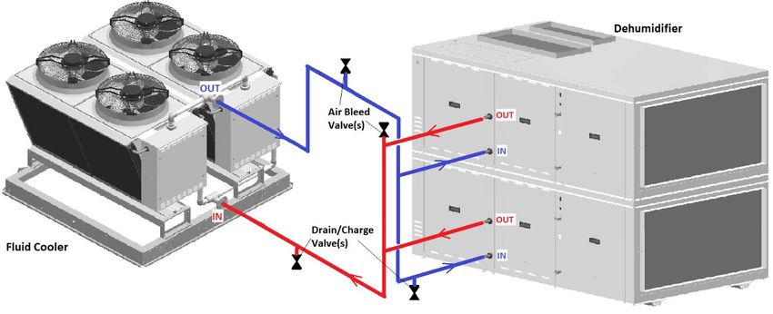
January, 2021 23 Dectron Dehumidifier Install ManualFluid Cooler Piping (NG models)
Line Set Selection and Sizing
• Refer to dehumidifier and/or fluid cooler main labels for line set typical diameter (both lines, supply and return,
are normally of the same size); note that size may differ from respective piping connections size at the
dehumidifier and fluid cooler.
o Typical line set diameter accounts for system proper operation if line set total equivalent length does
not exceed (approx.):
200’ – for NG-V-02 fluid cooler model*
300’ – for NG-V-12 fluid cooler model
450’ – for other fluid cooler models
o If the total equivalent length exceeds above value, the line set diameter must be upsized to next size
(e.g., step up diameter from 1 ¼” to 1 ½”). Contact the factory for more details, if needed**.
* in some cases, NG-V-02 fluid cooler model may accommodate higher total equivalent length with typical diameter –
contact the factory for details.
** typically, the fluid cooler is provided with pump package or serves the dehumidifier, equipped with its own pump,
therefore no additional pump is needed. However, in some cases (fluid cooler and dehumidifier are not packaged with
pump or in case of extremely high total equivalent length, etc.) additional’ pump may be required. Contact the factory if
needed.
• Standard recommended pipe and fitting materials are PVC, steel and copper. Other materials may also be
suitable – refer to material applicability according to given application (system media, max working pressure,
temperature, etc.). For outdoor piping, use only
Piping
Ensure proper piping support and bracing is in place at piping manufacturer recommended intervals AND
terminations – fluid cooler and dehumidifier pipe terminations do not provide structural support for piping.
Use outdoor-rated UV-stabilized PVC, or other material.
Proper piping practices (cleaning, sanding, reaming, wet-ragging during soldering, etc.) and bonding methods,
respective to pipe and fittings material (soft soldering, gluing, etc.) must be followed.
Fluid cooler and dehumidifier pipe terminations stickers (IN/OUT) refer to respective equipment:
o Identify correct system pipe terminations (typically labeled as “AC fluid” or “Cooling”)
o Connect fluid cooler OUT to dehumidifier IN; connect fluid cooler IN to dehumidifier OUT.
Install valves/devices to isolate, drain, charge and remove the air from the fluid cooler and line set.
o Fluid cooler typically is not provided with isolating valves – install as needed.
o Install drain/charge valve(s) at the lowest point(s) of the line set; install air bleeding valve(s) at the top
point(s) of the line set (see Pic. G.3, (A) and (B)).
o Fluid cooler and dehumidifier would typically have drain/charge valves installed at their lowest point(s).
o Pump package (if fluid cooler is equipped or provided separately with one) typically includes pump with
pressure gauges and expansion tank; same applies to NP series dehumidifiers (pump with pressure
gauges and expansion tank would normally be part of the dehumidifier).
Pic. G.3 (A) shows typical piping schematic for single fluid cooler serving single cooling circuit. Piping schematic
for single fluid cooler serving multiple cooling circuits (200 series NE dehumidifiers etc.) is shown on Pic. G.3 (B).
o NOTE: the given schematics are example only - the design, provision and installation of actual fluid
cooler piping is not manufacturer responsibility and is to be done by a third party.
Dectron Dehumidifier Install Manual 24 January, 2021Pressure Testing and Charging
• Refer to the fluid cooler and/or dehumidifier’s main label and
submittal documentation for operating pressure and cooling
media selection.
o Typically, mixture of food grade propylene glycol
(with rust inhibitors added) and distilled water is
used as a cooling fluid. The mixing ratio is typically
30-35% glycol; however, a higher glycol
concentration (e.g., 50%) could be used for northern
application – refer to the equipment submittal
documentation.
o To calculate approximate (!) Total System Volume
(amount of fluid required for system charging), add
Internal Fluid Cooler Volume (see submittal
documentation) to Line Set Volume (calculate based
on the used pipe diameter and line set actual length).
Increase calculated Total System Volume by 3-5% -
final charge of the system would be determined
during the charging (see below).
• Charge system at its lowest point and bleed the air out at the
system top point(s); charging at multiple lowest points (at
fluid cooler and dehumidifier) may be required.
o Use a separate charging pump. The dehumidifier
and/or fluid cooler pump(s) are selected/designed to
maintain fluid circulation and not be used for
charging. Ensure fluid is clean, free of any debris etc.
o Ensure thorough air removal from the system –
airlocks will prevent system from operating properly.
o Ensure that static pressure at the highest point of the
system is at least 15-20 psi. Verify it after bleeding all
the air from the system. Pic. G.3 (A)
Pic.G.3 (B)
January, 2021 25 Dectron Dehumidifier Install ManualOther Piping Systems and Special Cases
Space Heating and Space Cooling Hydronic Systems
Requirements, outlined in Piping Connection General Considerations (see above), apply to all types of space heating
and/or space cooling fluid systems (water, glycol, etc.) – refer to respective piping termination labels (IN/OUT), main
label (for line sizing) etc.
ATTENTION! If steam space heating coil is used – follow respective Code(s) recommendations, field practices
and steam coil and associated equipment (valves etc.) manufacturer’s guidance.
Gas-fired Space Heaters (duct gas heater, gas boiler, etc.)
Follow respective gas heater manufacturer requirements, as well as respective local codes, when piping and
connecting gas line to the heater (pipe sizing, supplied gas pressure, etc.). Refer to heater or dehumidifier
labels and stickers to locate gas connection.
Indoor-installed gas heater (boiler, duct heater, etc.) must be equipped with flue gas venting system – consult
gas heater manufacturer for proper venting system selection.
o Gas heater, packaged with the outdoor dehumidifier, normally would have provision for flue gas
venting, however in some cases (strong wind influences, location specifics, etc.) additional venting
system may be also required – consult gas heater manufacturer for proper type selection.
“Split-Cut” dehumidifier - piping assembly
When dehumidifier is provided from the factory in sections, field-assembly is required, including dehumidifier
internal piping reassembly.
Normally, such dehumidifiers are accompanied with Disassembly and Assembly Instructions – refer as needed.
Remove cups/plugs and join pipes respectively.
o To facilitate reassembly and avoid ambiguity, closely
located pipes are cut at the factory in “checkered”
pattern (see Pic. G.5) – once dehumidifier sections are
aligned properly, respective pipes would align too.
o Follow standard field practices, applicable to respective
pipe material/type and joining methods; ensure that
Pic.G.5
pipes and couplers are properly cleaned, sanded,
reamed, etc. as applicable. Normally, respective couplers are provided with the dehumidifier.
Pressure test/test for leaks re-joined piping and charge/upcharge re-joined circuit with respective fluid.
o Refer to dehumidifier submittal documentation and main label for respective circuits operating
pressure and media (water/glycol type and mixture ratio, type of refrigerant, etc.).
Follow proper field practices working with refrigeration circuits (brazing with nitrogen,
vacuuming, etc.); refer to recommendations in Outdoor Condenser Piping (see above).
o Depending on various circumstances, split-cut dehumidifier could be shipped with piping circuits
completely empty or partially charged – verify fluid presence in the circuit prior.
Normally, water and/or glycol circuits are provided empty – once joined, circuit must be
charged fully. Refer to Fluid Cooler Piping recommendations for charging.
• Fill/upcharge water/glycol at the bottom of the system, bleed the air from ALL top
bleeding valves (manual and automatic). Ensure all air is bled out. Upcharge, if
needed, to achieve min 20-30 psi static pressure at the bottom of circuit.
Dectron Dehumidifier Install Manual 26 January, 2021 Refrigeration circuits, depending on dehumidifier type, size and number of splits/sections,
could be provided completely empty or partially charged: be aware of refrigerant content in
the circuits and the way circuits were split at the factory.
Typically, if the dehumidifier is partially charged (normally, NP series):
• Compressor(s) and receiver(s) valves are closed and
• Evaporator coil(s) as well as suction line (up to compressor valve) and pump down
liquid line (up to receiver valve) are empty, rest of circuit(s) contain refrigerant.
Filter-drier core normally is provided separately for installation before vacuuming of
the circuit’s empty section.
Refrigeration circuit(s) final charge may need to be verified and adjusted (as needed) during
dehumidifier start. For current upcharge adjustment, refer to refrigerant level in receiver
sight glasses: top sight glass float should be at the bottom, bottom – at the top.
Finalize piping reassembly:
o As needed - retighten pipe braces, reinstall piping insulation (refrigeration circuit suction line(s),
chilled water coils line(s), etc.)
Remote Gas Boiler Package Installation and Piping Connection
Normally, dehumidifiers provided with a gas boiler package are
accompanied with the boiler manual and Remote Boiler Package
Installation and Start Up Instructions – refer as needed.
Air bleed
Venting and Gas connections. IN valve
If package includes two boilers, connect gas and venting to each
boiler separately.
Water piping connections. OUT Gas Conn.
Boiler package piping recommendations are similar to ones, outlined in
Fluid Cooler Piping (see above):
Normally, pipe line size could be kept same as the boiler package
pipe stubs; if line set total equivalent length exceeds 100’ - upsize
to next pipe size.
Boiler package pipe stubs are labeled respectively (IN and OUT – see
Pic. G.5). Connect boiler package OUT to dehumidifier IN; connect
boiler package IN to dehumidifier OUT.
o ATTENTION! Separate boiler packages are tested at the
factory, using “test loop” – short pipe connecting boiler Fill/drain
package IN and OUT stubs. Such loop is normally removed valve
at the factory; if this loop is still in place – remove it to
connect pipe line set
Pic.G.5
Once piped, pressure test and charge heating system (boiler
package, line set and coil) - refer to the dehumidifier’s main label
and submittal documentation for operating pressure and heating media selection:
o Both, distilled water or water-glycol mixture (approx. ratio is 30-35% of food grade propylene glycol)
are suitable for boiler package – refer to given dehumidifier submittal documentation.
o Recommended static pressure is approx. 40-50 psi
January, 2021 27 Dectron Dehumidifier Install ManualElectric Connection: power, control and communication
WARNING! All work must be done by qualified/licenced personnel in accordance with local and national
Codes, Standards and Regulations as well as proper field practices, respective submittal documentation and
manufacturer recommendations.
CAUTION! When connecting the equipment to external mechanical and electrical systems, refer to
submittal documentation and equipment labels and stickers for piping connection details.
CAUTION! Use copper conductors only. Equipment electrical and control terminals are not designed to
accept other types of conductors. Use of aluminium or other wiring may result in galvanic corrosion and/or
overheating that may cause equipment malfunction and/or failure and would void the warranty.
Electrical Connection - General Considerations
Select power supply wire gauge and, as/when needed, external power apparatuses (disconnects, breakers,
etc.) according to equipment electric data (MCA, MOP, etc.), provided on the main label, as well as respective
local and national codes and regulations.
Equipment (dehumidifier, OACC, OAFC etc.) are accompanied with their respective wiring diagrams, depicting
equipment internal wiring and terminals for external connection (power supply, control terminals, etc.) – refer
as needed.
Properly seal all penetrations made/used in the equipment cabinet outer walls. Failure to due so may result in
water/humid air infiltration that could lead to equipment malfunction or damage.
Ensure that all metal shards and filings are swept to avoid possible corrosion or damage to electrical
components. Ensure that wires are properly protected/isolated from the equipment cabinet sharp edges, hot
surfaces, etc.
Equipment Main Power Connection
Main (‘high”) power is to be brought to equipment main PDB (power distribution block, see Pic. H.1 (b)), located in
the main electric panel – refer to equipment labels and manual for panel and PDB location reference. If equipment
has a disconnect, power must be brought there (Pic. H.1(a)) – disconnect would be factory-wired to the PDB or
devices directly. Normally, Bring power here
OACC and OAFC are
equipped with disconnects,
as well as most NP series
dehumidifiers.
Verify that proper
voltage and number of
wires (single -phase Vs
three-phase – see Pic.)
are connected to the
equipment – refer to the Ground lug
main label and submittal
documentation. (b) Pic.H.1 (a)
Dectron Dehumidifier Install Manual 28 January, 2021You can also read