SERIES C VERTICAL FLOOR FAN COIL UNIT MODEL VFC/VFE/VFS
←
→
Page content transcription
If your browser does not render page correctly, please read the page content below
SERIES C VERTICAL FLOOR
                                                       FAN COIL UNIT

INSTALLATION, OPERATION & MAINTENANCE   Supersedes: ET115.24-NOM10 (1210)   Form ET115.24-NOM10 (815)

                                  MODEL VFC/VFE/VFS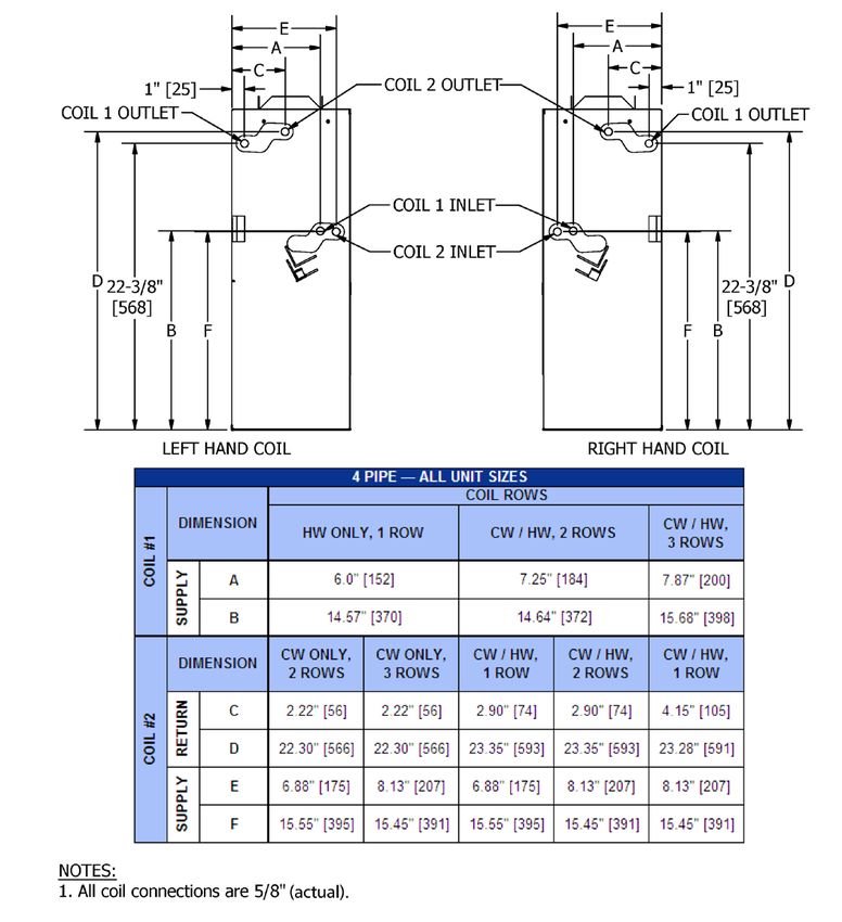
FORM ET115.24-NOM10 (815)
TABLE OF CONTENTS
TABLE OF CONTENTS................................................................................................................2
SAFETY SYMBOLS .....................................................................................................................3
SAFETY CONSIDERATIONS.......................................................................................................4
SECTION 1 - RECEIPT & INITIAL INSTALLATION...................................................................5
VF SERIES C FEATURES.......................................................................................................................5
PREFACE.................................................................................................................................................5
UNPACKING & INSPECTION ................................................................................................................6
HANDLING & INSTALLATION ...............................................................................................................6
COOLING/HEATING MEDIUM CONNECTIONS ....................................................................................7
DUCTWORK CONNECTIONS ................................................................................................................9
ELECTRICAL CONNECTIONS ..............................................................................................................9
SECTION 2 - START-UP ............................................................................................................10
GENERAL .............................................................................................................................................10
COOLING/HEATING SYSTEM .............................................................................................................10
AIR SYSTEM BALANCING ..................................................................................................................10
WATER SYSTEM BALANCING ...........................................................................................................11
MOTOR AND FAN DATA.......................................................................................................................11
CONTROLS OPERATION ....................................................................................................................12
SECTION 3 - NORMAL OPERATION & PERIODIC MAINTENANCE....................................12
GENERAL .............................................................................................................................................12
MOTOR/BLOWER ASSEMBLY ............................................................................................................13
COIL ......................................................................................................................................................13
ELECTRIC RESISTANCE HEATER ASSEMBLY .................................................................................13
FAN DECK.............................................................................................................................................13
ELECTRIC HEAT SELECTION CHART................................................................................................14
TOP PANEL REMOVAL (VFE, VFS).....................................................................................................14
ELECTRICAL WIRING & CONTROLS .................................................................................................14
VALVES & PIPING.................................................................................................................................14
FILTERS, THROWAWAY ......................................................................................................................14
WALL RECESSING PANEL..................................................................................................................15
DRAIN....................................................................................................................................................15
REPLACEMENT PARTS ......................................................................................................................15
SECTION 4 - INSPECTION, INSTALLATION & START-UP CHECKLIST.............................16
SECTION 5 - DIMENSIONAL DRAWINGS...............................................................................17
MODEL VFC - CONCEALED FAN COIL UNIT.....................................................................................17
MODEL VFE - EXPOSED FAN COIL UNIT W/ STAMPED SUPPLY GRILLE......................................18
MODEL VFS - EXPOSED SLOPE TOP FAN COIL UNIT W/ STAMPED SUPPLY AIR GRILLE.........19
OUTSIDE AIR DAMPER........................................................................................................................20
OUTSIDE AIR WALL BOX ASSEMBLY................................................................................................21
RETURN AIR TOE KICK.......................................................................................................................21
MODEL VFC - RECESSED WALL PANEL...........................................................................................22
FALSE BACK ASSEMBLY & DIMENSIONAL DRAWINGS..................................................................23
PARAMETRIC CABINET.......................................................................................................................24
PIPING PACKAGE SPACE CONSTRAINTS........................................................................................26
TROUBLESHOOTING GUIDE FOR FAN COIL RELAY BOARD.........................................................27
EXAMPLE WIRING DIAGRAM..............................................................................................................29
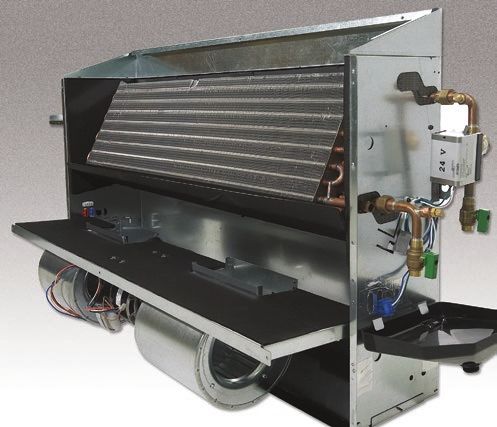
COIL CONNECTION LOCATIONS........................................................................................................30
2 ENVIRO-TEC
FORM ET115.24-NOM10 (815)

                                          SAFETY SYMBOLS
The following symbols are used in this document to alert the reader to areas of potential hazard:

             DANGER indicates an imminently                       CAUTION identifies a hazard which
             hazardous situation which, if not                    could lead to damage to the machine,
             avoided, will result in death or serious             damage to other equipment and/or
             injury.                                              environmental pollution. Usually an
                                                                  instruction will be given, together with
                                                                  a brief explanation.

             WARNING indicates a potentially                      NOTE is used to highlight additional
             hazardous situation which, if not                    information which may be helpful to
             avoided, could result in death or                    you.
             serious injury.

ENVIRO-TEC                                                                                               3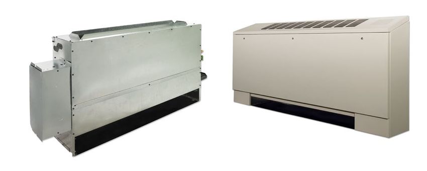
FORM ET115.24-NOM10 (815)

                                      SAFETY CONSIDERATIONS
The equipment covered by this manual is designed for        All assemblies must be adequately
safe and reliable operation when installed and operated     secured during lifting and rigging by
within its design specification limits. To avoid personal   temporary supports and restraints until
injury or damage to equipment or property while             equipment is permanently fastened
installing or operating this equipment, it is essential
                                                            and set in its final location.
that qualified, experienced personnel perform these
functions using good judgment and safe practices. See
the following cautionary statements.                        All unit temporary and permanent
                                                            supports must be capable of safely
            ELECTRICAL SHOCK HAZARDS.                       supporting the equipment’s weight and
            All power must be disconnected                  any additional live or dead loads that
            prior to installation and serving this          may be encountered. All supports must
            equipment. More than one source of              be designed to meet applicable local
            power may be present. Disconnect all            codes and ordinances.
            power sources to avoid electrocution
            or shock injuries.                              All fastening devices must be designed
                                                            to mechanically lock the assembly
            MOVING PARTS HAZARDS. Motor                     in place without the capability of
            and Blower must be disconnected prior           loosening or breaking away due to
            to opening access panels. Motors can            system operation and vibration.
            start automatically, disconnect all
            power and control circuits prior to             Secure all dampers when servicing
            servicing to avoid serious crushing or          damper, actuator or linkages. Dampers
            dismemberment injuries.                         may activate automatically, disconnect
                                                            control circuits or pneumatic control
            HOT PARTS HAZARDS. Electric                     systems to avoid injury.
            Resistance heating elements must be
            disconnected prior to servicing. Electric       Protect adjacent flammable materials
            Heaters may start automatically,                when brazing, Use flame and heat
            disconnect all power and control                protection barriers where needed.
            circuits prior to servicing to avoid            Have fire extinguisher available and
            burns.                                          ready for immediate use.

            Check that the unit assembly and
            component weights can be safely
            supported by rigging and lifting
            equipment.

 4                                                                                      ENVIRO-TEC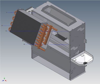
FORM ET115.24-NOM10 (815)

                        SECTION 1 - RECEIPT & INITIAL INSTALLATION
                                                 VF SERIES C FEATURES
                                                     (Actual unit will vary by order)

                                       5                                      10

                                                                                                     ITEM   QTY    TITLE
                                                                                                     1      2     COVER, BOTTOM, POCKET, VFE/S, SERIES C
                                                                                                     2      2     SUPPORT BRACE, BOTTOM, VFE, SERIES C
                                                                                                     3      2     PANEL, SIDE, EXTERNAL, SERIES C
                                                                                                     4      1     PANEL, FRONT, VFE/S, SERIES C
                                                                                                     5      1     PANEL, TOP, VFE, SERIES C
                                                                                                     6      1     BACK PANEL, VF, SERIES C
                    3                                                                                7      1     DRIP TRAY, VF, SERIES C
                                                     10                                              8      1     ASSY, FAN DECK, VF, SERIES C
                                                19                                                   9      1     PANEL, BOTTOM, VF, SERIES C
                                                                                                     10     2     BRACKET, COIL, MOUNTING, VF, SERIES C
                                                                                                     11     1     PANEL, BLOWER COVER, VF, SERIES C
              15                            2             18                                         12     1     ASSY, AUXILLIARY DRAIN PAN
                                                                                                     13     1     RACK, FILTER, VFC, SERIES C
                                                                                                     14     1     FILTER
        16                                                                                           15     1     CONTROL ENCLOSURE
                                                                                                     16     1     CONTROL ENCLOSURE COVER
                                                                                                     18     1     ASSY, COIL, VF
                                       14                                                            19     1     EH ASSEMBLY, VF, SERIES C
                                                                                       10            20     1     ASSY, OUTSIDE AIR, VF
                                                                                   7        20       21     1     PANEL, TOE SPACE, W/SLOTS, VFS SERIES C
                              1                                           8
                                                                                                 3

                                                                    12

                                                               9
                                                                              2
                                                13
                                                      1
                                  11

                          4
              21

PREFACE
Johnson Controls fan coils represent a prudent                           The equipment covered by this manual is available with
investment which can, with proper installation,                          a vast variety of options and accessories. Consult the
operation, and regular maintenance, give trouble-free                    approved unit submittal, order acknowledgement, and
operation and long service.                                              other manuals for details on the options and accessories
                                                                         provided with the equipment on each project.
Your equipment is initially protected under the
manufacturer’s standard warranty; however, this                                         No attempt should be made to handle,
warranty is provided under the condition that the steps                                 install, or service any unit without
outlined in this manual for initial inspection, proper                                  following safe practices regarding
installation, regular periodic maintenance, and everyday                                mechanical equipment.
operation of the equipment be followed in detail. This
manual should be fully reviewed in advance of any
actual work being done on the equipment. Should
any questions arise, please contact your local Sales                                    Fan coil units are designed for indoor
Representative or the factory BEFORE proceeding.                                        use only. Do not install or store fan
                                                                                        coils in an outdoor environment.

ENVIRO-TEC                                                                                                                                                  5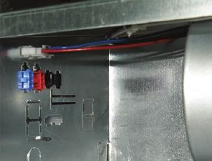
FORM ET115.24-NOM10 (815)

             All power must be disconnected before            All shipments are made F.O.B. factory and it is the
             any installation or service should be at-        responsibility of the receiving party to inspect the
             tempted. More than one power source              equipment upon arrival. Any obvious damage to the
             may be supplied to a unit. Power to              carton and/or its contents should be recorded on the bill
             remote mounted control devices may               of lading and a claim should be filed with the freight
                                                              carrier.
             not be supplied through the unit.
                                                              After determining the condition of the carton exterior,
             Never wear bulky or loose fitting cloth-         carefully remove each unit from the carton and inspect
             ing when working on any mechanical               for hidden damage. At this time check to make sure that
             equipment. Gloves should only be                 “furnished only” items such as switches, thermostats,
             worn when required for proper pro-               etc. are accounted for. Any hidden damage should be
             tection from heat or other possible in-          recorded and immediately reported to the carrier and a
             jury. Safety glasses or goggles should           claim filed as before. In the event a claim for shipping
             always be worn when drilling, cutting,           damage is filed, the unit, shipping carton, and all packing
             or working with chemicals such as                must be retained for physical inspection by the freight
             refrigerants or lubricants.                      carrier.

                                                              All equipment should be stored in the factory-shipping
             Never pressurize any equipment be-               carton with internal packing in place until installation.
             yond specified operating pressures.
             Always pressure test with some inert             At the time of receipt, the equipment type and
             fluid or gas such as clear water or dry          arrangement should be verified against the order
             nitrogen to avoid possible damage or             documents. Should any discrepancy be found, the local
             injury in the event of a leak or compo-          Sales Representative should be notified immediately
             nent failure during testing.                     so that the proper action may be instituted. Should
                                                              any question arise concerning warranty repairs, the
             Always protect adjacent flammable                factory must be notified BEFORE any corrective
             material when welding or soldering.              action is taken. Where local repairs or alterations can
                                                              be accomplished, the factory must be fully informed as
             Use suitable heat shield material to
                                                              to the extent and expected cost of those repairs before
             contain sparks or drops of solder.               work is begun. Where factory operations are required,
             Have fire extinguisher available for             the factory must be contacted for authorization to return
             use when welding or brazing.                     equipment and a Return Authorization Number will be
                                                              issued. Unauthorized return shipments of equipment
The manufacturer assumes no responsibility for personal       and shipments not marked with an authorization number
injury or property damage resulting from improper             will be refused. In addition, the manufacturer will not
or unsafe practices during the handling, installation,        accept any claims for unauthorized expenses.
service, or operation of any equipment.
                                                              HANDLING & INSTALLATION
UNPACKING & INSPECTION
                                                              While all equipment is designed for durability and
All units are carefully inspected at the factory throughout   fabricated for sturdy construction and may present a
the manufacturing process under a strict detailed quality     rugged appearance, great care must be taken to assure
assurance program, and where possible, all major              that no force or pressure be applied to the coil, piping
components and subassemblies are carefully tested for         or drain stub-outs during handling. Also, depending
proper operation and verified to be in full compliance        on the options and accessories, some units could
with the factory manufacturing documents. Customer            contain delicate components that may be damaged by
furnished components such as control valves, switches         improper handling. Wherever possible, all units should
and DDC controls are not factory tested.                      be maintained in an upright position and handled by
                                                              the chassis as close as possible to the mounting point
Each unit is carefully packaged for shipment to avoid         locations.
damage during normal transport and handling. The
equipment should always be stored in a dry place in the
proper orientation as marked on the carton.
 6                                                                                                          ENVIRO-TEC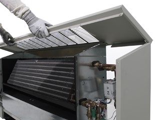
FORM ET115.24-NOM10 (815)

In the case of a full cabinet unit, the unit must obviously   If equipped with optional leveling legs, the legs can
be handled by the exterior casing. This is acceptable         be adjusted with a wrench before anchoring the unit
providing the unit is again maintained in an upright          in place.
position and no impact forces are applied that may
damage internal components or painted surfaces. The           The type of mounting device is a matter of choice,
equipment covered in this manual IS NOT suitable              however the mounting point should always be that
for outdoor installations. The equipment should never         provided in the chassis, or cabinet. Refer to the unit
be stored or installed where it may be subjected to a         product drawing for mounting hole location and sizes.
hostile environment such as rain, snow, or extreme            See pages 17, 18 or 19.
temperatures.
                                                              If equipped with optional falseback spacers or subbases,
During and after installation, special care must be taken     these accessories must first be assembled and mounted
to prevent foreign material such as paint, plaster, and       to the unit before anchoring.
drywall dust from being deposited in the drain pan or
on the motor or blower wheels. Failure to do so may           After mounting the unit, it is then ready for the various
have serious adverse effects on unit operation and in         service connections such as water, drain and electrical.
the case of the motor and blower assembly, may result         At this time it should be verified that the proper types
in immediate or premature failure. All manufacturers’         of service are actually provided to the unit.
warranties are void if foreign material is deposited on
the motor or blower wheels of any unit. Some units and/       On those units requiring chilled water and/or hot water,
or job conditions may require some form of temporary          the proper line size and water temperature should be
covering during construction.                                 available to the unit. In the case of refrigerant cooling,
                                                              the proper line size and refrigerant type should be
While the manufacturer does not become involved               available at the unit. The auxiliary drain pan is shipped
in the design and selection of support methods and            loose for field installation. See the Auxiliary Drain Pan
components, it should be noted that unacceptable              Installation Details for instructions (next page). On
system operating characteristics and/or performance           units with steam heating coils, the proper line sizing
may result from improper or inadequate unit structural        and routing should be verified and the maximum steam
support. In addition, adequate clearance must be              pressure applied to the unit should never exceed 15
provided for service and removal of the equipment and         psig. The drain piping and steam trap should be sized
its accessory components. Anchoring the equipment in          and routed to allow for proper condensate flow. The
place is accomplished by using the mounting points            electrical service to the unit should be compared to
provided and positioning the unit to maintain the unit        the unit nameplate to verify compatibility. The routing
on a LEVEL plane. The drain pan is internally sloped          and sizing of all piping, and the type and sizing of all
toward the outlet connection. Care must be taken to           wiring and other electrical components such as circuit
insure that the unit drain pan does not slope away from       breakers, disconnect switches, etc. should be determined
the outlet connection.                                        by the individual job requirements and should not be
                                                              based on the size and/or type of connection provided
             The unit's drain pan is factory sloped           on the equipment. All installations should be made in
             toward the drain connection when the             compliance with all governing codes and ordinances.
             unit is installed level and plumb.               Compliance with all codes is the responsibility of the
                                                              installing contractor.

                                                              COOLING/HEATING MEDIUM CONNECTIONS
Vertical units are designed to be floor mounted or                         Toxic residues and loose particles
otherwise supported from below and bolted to the wall                      resulting from manufacturing and
structure through the mounting holes provide in the                        field piping techniques such as joint
chassis. Vertical concealed units are designed to be                       compounds, soldering flux, and metal
floor mounted or otherwise supported from below and                        shavings may be present in the unit
may be anchored directly through the cabinet back.                         and the piping system. Special con-
Units with leveling legs must be anchored through the
                                                                           sideration must be given to system
cabinet back.
                                                                           cleanliness when connecting to solar,
                                                                           domestic or potable water systems.
ENVIRO-TEC                                                                                                            7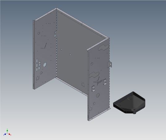
FORM ET115.24-NOM10 (815)

Submittals and Product Catalogs detailing unit operation,   In the case of field installed valves and piping, the
controls, and connections should be thoroughly              chilled water valve cluster (or expansion valve on DX
reviewed BEFORE beginning the connection of the             units) should be installed in such a way that any dripping
various cooling and/or heating mediums to the unit.         or sweating is contained in the auxiliary drain pan or
                                                            other device.
All accessory valve packages should be installed as
required, and all service valves should be checked for      In the case of factory mounted piping packages, it
proper operation.                                           is important to verify that all unions are tight, since
                                                            shipping and handling may cause loosening.
If coil and valve package connections are to be made
with “sweat” or solder joint, care should be taken to       After the connections are completed, the system should
assure that no components in the valve package are          then be tested for leaks. Since some components are not
subjected to a high temperature which may damage seals      designed to hold pressure with a gas, hydronic systems
or other materials. Many two-position electric control      should be tested with water.
valves, depending on valve operation, are provided with
a manual-opening lever. This lever should be placed                      All water coils must be protected from
in the “open” position during all soldering or brazing                   freezing after initial filling with water.
operations. Valve bodies should be wrapped with a wet                    Even if the system is drained, unit coils
rag to help dissipate heat encountered during brazing.                   may still hold enough water to cause
                                                                         damage when exposed to temperatures
If the valve package connection at the coil is made with
                                                                         below freezing.
a union, the coil side of the union must be prevented
from twisting (“backed up”) during tightening to prevent
                                                            Refrigerant systems should be tested with dry nitrogen
damage to the coil tubing. Over-tightening must be
                                                            rather than air to prevent the introduction of moisture
avoided to prevent distorting the union seal surface and
                                                            into the system. In the event that leaking or defective
destroying the union.

                                                            NOTES:
                                                            1. Bend lower support tabs down 90°.
                                                            2. Bend upper support tabs up 90°.
                                                            3. Position drain pan in place and then bend upper
                                                               support tabs down until pan is secure.
                                                            4. Bend float switch mount out 90° if needed.
                                                            5. Standard pan shown; typical for extended pan.

NOTE:
Installing contractor must ensure that the connected
drain piping maintains the proper pan orientation.

 8                                                                                                       ENVIRO-TEC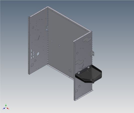
FORM ET115.24-NOM10 (815)

components are discovered, the Sales Representative           ELECTRICAL CONNECTIONS
must be notified BEFORE any repairs are attempted.
All leaks should be repaired before proceeding with
the installation.

After system integrity has been established the piping
should be insulated in accordance with the project
specifications. ALL chilled water piping and valves or
refrigerant suction piping not located over drain pans
must be insulated to prevent damage from sweating.
This includes factory and field piping inside the unit
cabinet.

The drain should always be connected and piped to an
acceptable disposal point. For proper moisture carry-
off, the drain piping should be sloped away from the
unit at least 1/8" per foot. A drain trap may be required
by local codes and it is strongly recommended for odor
containment.
                                                               ELECTRICAL QUICK CONNECT
DUCTWORK CONNECTIONS                                           VF units allow for a single technician to service the fan/
All ductwork and/or supply and return grilles should           motor by keeping the fan deck to less than 44".  Motors
                                                               are supplied with quick connectors to allow electrical ser-
be installed in accordance with the project plans and          vice without the need for tools.
specifications. If not included on the unit or furnished
from the factory, supply and return grilles should be         ELECTRICAL CONNECTIONS
provided as recommended in the product catalog.               The unit nameplate lists the unit electrical characteristics
                                                              such as the required supply voltage, fan and heater
All units must be installed in non-combustible areas.         amperage and required circuit ampacities. The unit-
                                                              wiring diagram shows all unit and field wiring. Since
Some models are designed to be connected to duct-work         each project is different and each unit on a project may
with a MINIMUM amount of external static pressure.            be different, the installer must be familiar with the
These units may be damaged by operation without the           wiring diagram and nameplate on the unit BEFORE
proper ductwork connected. Consult the approved               beginning any wiring. All components furnished for
submittals and the product catalog for unit external          field installation, by either the factory or the controls
static pressure limitations.                                  contractor should be located and checked for proper
                                                              function and compatibility. All internal components
Units provided with outside air for ventilation should        should be checked for shipping damage and all electrical
have some form of low temperature protection to               connections should be tightened to minimize problems
prevent coil freeze-up.                                       during start-up.
It should be noted that none of these methods would           Any devices such as fan switches or thermostats
adequately protect a coil in the event of power failure.      that have been furnished from the factory for field
The safest method of freeze protection is to use glycol       installation must be wired in strict accordance with the
in the proper percent solution for the coldest expected       applicable wiring diagrams. Failure to do so could result
air temperature.                                              in personal injury or damage to components and will
                                                              void all manufacturers’ warranties.
The manufacturer assumes no responsibility for
undesirable system operation due to improper                  The fan motor(s) should never be controlled by any
design, equipment or component selection, and/or              wiring or device other than the factory furnished
installation of ductwork, grilles, and other field supplied   switch, thermostat/switch combination, without factory
components.                                                   authorization.

ENVIRO-TEC                                                                                                               9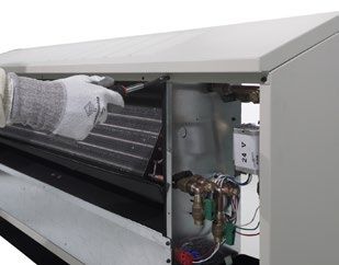
FORM ET115.24-NOM10 (815)

All field wiring should be done in accordance with                        During system filling, air venting from
governing codes and ordinances. Any modification of                       the unit is accomplished by the use of the
the unit wiring without factory authorization will result                 standard, manual or optional automatic air
in voiding of all factory warranties and will nullify any                 vent fitting installed on the coil. In the case
agency listings.                                                          of the manual air vent fitting, the screw
                                                                          should be turned counterclockwise no more
The manufacturer assumes no responsibility for any            than 1-1/2 turns to operate the air vent. Automatic air
damages and/or injuries resulting from improperly field       vents may be unscrewed one turn counterclockwise
installed or wired components.                                to speed initial venting but should be screwed in for
                                                              automatic venting after start-up operations.
Fan speed can be varied with optional SCR. SCR is
shipped wired to high speed tap only. Wiring to medium                     The air vent provided on the unit is not
or low taps could cause excessive vibration, noise and                     intended to replace the main system air
overheating which can lead to motor failure.                               vents and may not release air trapped
                                                                           in other parts of the system. Inspect the
                                                                           entire system for potential air traps and
          SECTION 2 - START-UP                                             vent those areas as required, indepen-
GENERAL                                                                    dently. In addition, some systems may
                                                                           require repeated venting over a period
Before beginning any start-up operation, the start-                        of time to properly eliminate air from
up personnel should familiarize themselves with the                        the system.
unit, options and accessories, and control sequence to
understand the proper system operation. All personnel                      Fan coil units are not intended for use
should have a good working knowledge of general                            as temporary heat/cool or ventilation
start-up procedures and have the appropriate start-up                      during building construction. The
and balancing guides available for consultation.                           units are not designed or equipped
                                                                           to operate in a dusty environment.
The initial step in any startup operation should be a final                Fan wheels can become coated with
                                                                           construction dust, resulting in an
visual inspection. All equipment, plenums, duct-work,                      unbalanced wheel. This can in turn
and piping should be inspected to verify that all systems                  contribute to reduced motor life. Inlet
are complete and properly installed and mounted, and                       filters cannot provide adequate pro-
that no debris or foreign articles such as paper or drink                  tection as they will quickly become
cans are left in the units or other areas. Each unit should                clogged. Failure to operate the unit
be checked for loose wires, free blower wheel operation,                   in the condition outlined above could
and loose or missing access panels or doors. Except as                     result in damage to the equipment or
required during start-up and balancing operations, no                      building and furnishings, and/or void
fan coil units should be operated without all the proper                   all manufacturer’s warranties.
ductwork attached, supply and return grilles in place,
                                                                           Do not operate unit without panels
and all access doors and panels in place and secure.                       fully installed.
A clean filter of the proper size and type must also be
installed. Failure to do so could result in damage to the                  Do not allow supply or return air
equipment or building and furnishings, and/or void all                     grilles to be blocked.
manufacturers’ warranties.
                                                                           Make sure units are properly wired
COOLING/HEATING SYSTEM                                                     prior to unit startup.
Prior to the water system start-up and balancing, the
chilled/hot water systems should be flushed to clean          AIR SYSTEM BALANCING
out dirt and debris, which may have collected in the          All ductwork must be complete and connected, and all
piping during construction. During this procedure,            grilles, filters, access doors and panels must be properly
all unit service valves must be in the closed position.       installed to establish actual system operating conditions
This prevents foreign matter from entering the unit and       BEFORE beginning air balancing operations.
clogging the valves and metering devices. Strainers
should be installed in the piping mains to prevent            Each individual unit and attached ductwork is a unique
this material from entering the units during normal           system with its own operating characteristics. For this
operation.
 10                                                                                                         ENVIRO-TEC
FORM ET115.24-NOM10 (815)
reason, balance specialists who are familiar with all system balancing and this procedure should not be
procedures required to properly establish air distribution attempted by unqualified personnel. The system must
and fan system operating conditions normally do air be complete and all components must be in operating
balancing. Unqualified personnel should not attempt condition BEFORE beginning water system balancing
these procedures. Exposed units with no ductwork do operations.
not require air balancing other than selecting the desired
fan speed. Each hydronic system has different operating
characteristics depending on the devices and controls
After the proper system operation is established, in the system. The actual balancing technique may vary
the actual unit air delivery and the actual fan motor from one system to another.
amperage draw for each unit should be recorded in
a convenient place for future reference such as the After the proper system operation is established, the
inspection, installation, & start-up check sheet, a copy appropriate system operating conditions such as various
of which is provided at the back of this manual. Contact water temperatures and flow rates should be recorded
the Sales Representative or the factory for additional in a convenient place for future reference such as the
copies of this sheet. inspection, installation, & start-up check sheet, a copy
of which is provided on the back of this manual. Contact
WATER SYSTEM BALANCING the Sales Representative or the factory for additional
A complete knowledge of the hydronic system, its copies of this sheet.
components, and controls is essential to proper water
MOTOR AND FAN DATA
UNIT MOTOR H.P. 115 VOLTS 208-230 VOLTS 277 VOLTS
FAN SPEED # OF FANS
SIZE (QTY.) FLA WATTS FLA WATTS FLA WATTS
High 45 53 57
02 Medium (1) 1/50 1 0.40 35 0.27 41 0.21 44
Low 28 36 40
High 60 67 73
03 Medium (1) 1/20 1 0.60 48 0.40 54 0.31 60
Low 43 49 54
High 70 71 76
04 Meduim (1) 1/20 2 0.75 61 0.39 60 0.35 65
Low 58 52 58
High 80 81 87
06 Medium (1) 1/20 2 0.75 74 0.39 71 0.35 77
Low 61 59 64
High 114 109 114
08 Medium (1) 1/10 2 1.10 81 0.51 77 0.46 80
Low 71 66 70
High 132 140 144
10 Medium (2) 1/20 4 1.50 114 0.78 116 0.70 120
Low 107 101 106
High 142 147 154
12 Medium (2) 1/20 4 1.50 126 0.78 125 0.70 131
Low 114 107 114
NOTES:
1. VFE, 3-row coil, no EH, no toe kick, standard throw away panel filter.
2. Data was taken without ductwork.
3. Unit size 04, 06, 08, 10 and 12 data generated at 115v, 230v and 277v.
4. Unit size 02 & 03 data generated with 115v, 240v to 120v transformer(230v line voltage) and 277v to 120v transformer
(277v line voltage).
5. For FLA use unit voltage, and size at high speed.
ENVIRO-TEC 11FORM ET115.24-NOM10 (815)
Before and during water system balancing, conditions SECTION 3 - NORMAL OPERATION
may exist which can result in noticeable water
& PERIODIC MAINTENANCE
noise or undesired valve operation due to incorrect
system pressures. After the entire system is balanced, GENERAL
these conditions will not exist on properly designed Each unit on a job will have its own unique operating
systems. environment and conditions that may dictate a
maintenance schedule for that unit that is different
CONTROLS OPERATION from other equipment on the job. A formal schedule of
Before proper control operation can be verified all other regular maintenance and an individual unit log should
systems must be in proper operation. The correct water be established and maintained. This will help to achieve
and air temperatures must be present for the control the maximum performance and service life of each unit
function being tested. Some controls and features are on the job.
designed to not operate under certain conditions.
Information regarding safety precau-
A wide range of controls and electrical options and tions contained in the preface at the
accessories may be used with the equipment covered beginning of this manual should be
in this manual. Consult the approved unit submittals, followed during any service and main-
order acknowledgement, and other manuals for detailed tenance operations.
information regarding each individual unit and its
controls. Since controls and features may vary from For more detailed information concerning service
one unit to another, care should be taken to identify operations, consult your Sales Representative or the
the controls to be used on each unit and their proper Factory.
control sequence. Information provided by component
manufacturers regarding installation, operation, and
maintenance of their individual controls is available
upon request.
5 10
ITEM QTY TITLE
1 2 COVER, BOTTOM, POCKET, VFE/S, SERIES C
2 2 SUPPORT BRACE, BOTTOM, VFE, SERIES C
3 2 PANEL, SIDE, EXTERNAL, SERIES C
4 1 PANEL, FRONT, VFE/S, SERIES C
5 1 PANEL, TOP, VFE, SERIES C
6 1 BACK PANEL, VF, SERIES C
3 7 1 DRIP TRAY, VF, SERIES C
10 8 1 ASSY, FAN DECK, VF, SERIES C
19 9 1 PANEL, BOTTOM, VF, SERIES C
10 2 BRACKET, COIL, MOUNTING, VF, SERIES C
11 1 PANEL, BLOWER COVER, VF, SERIES C
15 2 18 12 1 ASSY, AUXILLIARY DRAIN PAN
13 1 RACK, FILTER, VFC, SERIES C
14 1 FILTER
16 15 1 CONTROL ENCLOSURE
16 1 CONTROL ENCLOSURE COVER
18 1 ASSY, COIL, VF
14 19 1 EH ASSEMBLY, VF, SERIES C
10 20 1 ASSY, OUTSIDE AIR, VF
7 20 21 1 PANEL, TOE SPACE, W/SLOTS, VFS SERIES C
1 8
3
12
9
2
13
1
11
21 4
12 ENVIRO-TECFORM ET115.24-NOM10 (815)
MOTOR/BLOWER ASSEMBLY
To access electrical limits, remove protective cover.
blowing air through the coil fins from the leaving
Motor/blower assembly can be removed by pulling two
screws from the frame. Fan deck designed to not exceed air face. Vacuuming should again follow this. Units
44". provided with the proper type of air filters, replaced
regularly, will require coil cleaning.
The type of fan operation is determined by the control
components and their method of wiring, and may vary
ELECTRIC RESISTANCE HEATER ASSEMBLY
from unit to unit. Refer to the wiring diagram for each
unit for that unit’s individual operating characteristics. Electric resistance heaters typically require no normal
Motors are permanently lubricated, PSC type and do not periodic maintenance when unit air filters are changed
require field lubrication. properly. Other conditions and equipment may affect the
operation and service life in the system. The two most
Should the assembly require more extensive service, important operating conditions for an electric heater are
the motor/blower assembly may be removed from the proper airflow and proper supply voltage. High supply
unit to facilitate such operations as motor or blower voltage and/or poorly distributed or insufficient airflow
wheel/housing replacement, etc. Dirt and dust should over the element will result in element overheating. This
not be allowed to accumulate on the blower wheel or condition may result in the heater cycling on the high
housing. This can result in an unbalanced blower wheel limit thermal cutout
condition that can damage a blower wheel or motor.
The wheel and housing may be cleaned periodically Sheathed type heaters provided have an automatic
using a vacuum cleaner and a brush taking care not to reset switch with a back-up high limit thermal switch.
dislodge the factory balancing weights on the blower Automatic reset switches are as the name implies; they
wheel blades. reset automatically after the heater has cooled down.
High limit thermal switches must be replaced once the
COIL circuit has been broken. The high limit thermal cutout
device is a safety device only and is not intended for
continuous operation. With proper unit application and
during normal operation, the high limit thermal cutout
will not operate. This device only operates when some
problem exists and ANY condition that causes high limit
cutout MUST be corrected immediately. High supply
voltage also causes excessive amperage draw and may
result in tripping of the circuit breaker or blowing of
the fuses on the incoming power supply.
FAN DECK
The fan/drain pan assembly is easily removable for
service access to motors and blowers at, or away from,
Remove screws to replace coil. the unit.
Coils may be cleaned in place by removing the motor/
blower assemblies and brushing the entering air face
between fins with a stiff brush. Cleaning with a vacuum
cleaner should follow brushing. If a compressed air
source is available, the coil may also be cleaned by
ENVIRO-TEC 13FORM ET115.24-NOM10 (815)
VF ELECTRIC HEAT SELECTION CHART (AMPS)
MBH 3.4 5.1 6.8 10.2 13.7 17.1 20.5 NOTES:
UNIT
KW 1.0 1.5 2.0 3.0 4.0 5.0 6.0
SIZE
VOLTS AMPS 1. Shaded areas of the electric heat selection
115 8.3 chart indicate kW and voltage options not
02 208 4.8 available.
240 4.2
277 3.6
115 8.3 12.5 2. Available voltages are single phase,
03 208 4.8 7.2 60 hertz.
240 4.2 6.3
277 3.6 5.4 3. Size heater for Leaving Air Temperature
115 8.3 12.5 16.7
04 208 4.8 7.2 9.6 (LAT) less than 104°F.
240 4.2 6.3 8.3
277 3.6 5.4 7.2 4. Silent, solid state heater relay is available
115 8.3 12.5 16.7 25.0
208 4.8 7.2 9.6 14.4 for heater currents less than 18 amps.
06
240 4.2 6.3 8.3 12.5
277 3.6 5.4 7.2 10.8 5. Ask your representative about continuously
115 8.3 12.5 16.7 25.0
208 4.8 7.2 9.6 14.4 19.2 modulating electric heat using SSR and special
08
240 4.2 6.3 8.3 12.5 16.7 control options.
277 3.6 5.4 7.2 10.8 14.4
115 8.3 12.5 16.7 25.0
10 208 4.8 7.2 9.6 14.4 19.2 24.0
240 4.2 6.3 8.3 12.5 16.7 20.8
277 3.6 5.4 7.2 10.8 14.4 18.1
115 8.3 12.5 16.7 25.0
12 208 4.8 7.2 9.6 14.4 19.2 24.0 28.9
240 4.2 6.3 8.3 12.5 16.7 20.8 25.0
277 3.6 5.4 7.2 10.8 14.4 18.1 21.7
TOP PANEL REMOVAL (VFS, VFE) When replacing any components such as fuses,
Depending on options and unit size, the top panel contactors, or relays, use only the exact type, size, and
may need to be removed to service or replace fan coil voltage component as furnished from the factory. Any
components. Top panel removal does not require the deviation without factory authorization could result
unit to be pulled away from wall, or for piping/electrical in personnel injury or damage to the unit and will
connections to be broken. Top panel is screwed onto void all factory warranties. All repair work should be
unit through front-accessible screws. Pull screws and done in such a manner as to maintain the equipment in
lift panel to remove. compliance with governing codes and ordinances or
testing agency listings.
More specific information regarding the use and
operating characteristics of the standard controls offered
by this manufacturer is contained in other manuals.
VALVES & PIPING
No formal maintenance is required on the valve package
components most commonly used with fan coil units
other than a visual inspection for possible leaks in the
course of other normal periodic maintenance. In the
event that a valve should need replacement, the same
precautions taken during the initial installation to protect
ELECTRICAL WIRING & CONTROLS the valve package from excessive heat should also be
The electrical operation of each unit is determined by used during replacement.
the components and wiring of the unit and may vary
from unit to unit. Consult the wiring diagram for the FILTERS, THROWAWAY
actual type and number of controls provided on each The type of throwaway filter most commonly used on
unit. The integrity of all electrical connections should be fan coil units should be replaced on a regular basis.
verified at least twice during the first year of operation. The time interval between each replacement should
Afterwards, all controls should be inspected regularly be established based on regular inspection of the filter
for proper operation. Some components may experience and should be recorded in the log for each unit. Refer to
erratic operation or failure due to age. Wall thermostats the product catalog for the recommended filter size for
may also become clogged with dust and lint and should each product type and size. If the replacement filters are
be periodically inspected and cleaned to provide reliable not purchased from the factory, the filters used should
operation. be the same type and size as that furnished from or
14 ENVIRO-TECFORM ET115.24-NOM10 (815)
recommended by the factory. Consult the factory for
applications using filter types other than the factory
standard or optional product.
DRAIN
The drain should be checked before initial start-up and
at the beginning of each cooling season to assure that the
lines are clear. If it is clogged, steps should be taken to
clear the debris so that condensate will flow easily.
Periodic checks of the drain should be made during the
cooling season to maintain a free flowing condensate.
Should the growth of algae and/or bacteria be a concern,
consult an air conditioning and refrigeration supply
organization familiar with local conditions for chemicals
available to control these agents.
REPLACEMENT PARTS
Factory replacement parts should be used wherever
possible to maintain the unit performance and
operating characteristics and the testing agency listings.
Filters are installed in a full metal u-carriage steel filter Replacement parts may be purchased through the local
rack. The filter rack is designed to slide in and out of the Sales Representative.
unit without the need for tools. To replace filter: slide
filter rack out of the front, pull filters from metal frame, Contact the local Sales Representative or the factory
insert new filters into metal frame and insert filters and before attempting any unit modifications. Any
frame into unit. Ensure that filter frame is completely modifications not authorized by the factory could result
reinstalled into the unit to prevent unfiltered air bypass in personnel injury and damage to the unit and could
or warping of filters. void all factory warranties.
WALL RECESSING PANEL When ordering parts, the following information must be
A wall panel is supplied to allow access to concealed fan supplied to ensure proper part identification:
coils. Perimeter frame must be permanently fastened to
1. Complete unit model number.
wall or other structure capable of supporting it. Panel
is designed for installation and removal from perimeter 2. Unit hand connection (right or left hand) while
frame by 1/4 turn fasteners. On panels with supply and facing into the return air stream.
return air, it is critical that unit presses against insulation 3. Complete part description including any num-
on panel. Failure to properly space unit and panel bers.
could result in air bypass and improper conditioning
of space. On warranty replacements, in addition to the information
previously listed, the project CO # that appears on the
unit nameplate, is required. Contact the factory for
authorization to return any parts such as defective parts
ENVIRO-TEC 15FORM ET115.24-NOM10 (815)
replaced in warranty. All shipments returned to the factory MUST be marked with a Return Authorization Number,
which is provided by the factory.
All equipment and components sold through the Parts Department are warranted under the same conditions as the
standard manufacturer’s warranty with the exception that the warranty period is 12 months unless the component is
furnished as warranty replacement. Parts furnished as warranty replacements are warranted for the remaining term
of the original unit warranties.
SECTION 4 - INSPECTION, INSTALLATION & START-UP CHECKLIST
Receiving & Inspection Ductwork Connections
o Unit received undamaged o Install ductwork, fittings and grilles as required
o Unit arrangement/hand correct o Control outside air for freeze protection
o Unit received complete as ordered o Proper supply and return grille type and size used
o Unit structural support complete and correct o Insulate all ductwork as required
Handling and Installation Electrical Connections
o Unit mounted level and square o Refer to unit wiring diagram
o Proper electrical service provided o All field wiring in code compliance
o Proper service switch/disconnect provided o Connect incoming power service or services
o Proper chilled water line size to unit
o Proper refrigerant line sizes to unit Unit Startup
o Proper steam condensate trap on return line o General visual unit and system inspection
o All services to unit in code compliance o Record ambient temperature
o Proper access provided for unit and accessories o Close all unit isolation valves
o Proper overcurrent protection provided o Fill systems with water/refrigerant
o Proper hot water line to unit o All ductwork and grilles in place
o Proper steam line sizes to unit o Start fans, etc.
o Proper steam supply pressure to unit o Check all ductwork and units for air leaks
(15psi max) o Record all final settings for future use
o All shipping screws and braces removed o Check all dampers for proper operation
o Verify proper heating operation
Cooling/Heating Connections o Check all piping for leakage
o Protect valve package components from heat o Record electrical supply voltage
o Connect field piping to unit o Check all wiring for secure connections
o Install drain line and traps as required o Flush water systems
o Install condensate pan under piping as required o Vent water systems as required
o Mount valve packages o All unit panels and filters in place
o Pressure test all piping for leaks o Check for overload condition of all units
o Insulate all piping as required o Balance air systems as required
o If the valve package connection at the coil is o Check piping and ductwork for vibration
made with a union, the coil side of the union o Verify proper cooling operation
must be prevented from twisting ("backed up") o Reinstall all covers and access panels
during tightening to prevent damage to the coil
tubing. Over-tightening must be avoided to
prevent distorting the union seal surface and
destroying the union.
16 ENVIRO-TECFORM ET115.24-NOM10 (815)
SECTION 5 - DIMENSIONAL DRAWINGS
MODEL VFC - CONCEALED FAN COIL UNIT
NOTES: DIMENSIONS
1. All dimensions are in inches [millimeters]. All dimensions UNIT MODEL A B C
VFC02 23 3/16 [589] 22 3/4 [578] 16" [406]
are 1/4" [6mm]. Metric vales are soft conversion.
VFC03 27 3/16 [691] 26 3/4 [679] 20" [508]
2. Junction box size and location varies w/unit features.
VFC04 33 3/16 [843] 32 3/4 [832] 26" [660]
Control options may be limited. Provide sufficient
VFC06 43 3/16 [1097] 42 3/4 [1086] 36" [914]
clearance to access electrical controls and comply
w/applicable codes and ordinances. Reduced height VFC08 45 3/16 [1148] 44 3/4 [1137] 38" [965]
control enclosure is standard with opposite end coils. VFC10 59 3/16 [1503] 58 3/4 [1492] 52" [1320]
3. Right hand coil connection shown. Left hand unit VFC12 67 3/16 [1707] 66 3/4 [1695] 60" [1524]
similar but opposite.
4. Some piping package options may require
extended drain pans.
5. Size 02 and 03 Models with 208/230vac or 277vac have 3 5/8" [92]
extended control enclosure.
B 3/4" M.P.T. AUXILIARY
MOUNTING HOLES DRAIN PAN CONNECTION
(2 PLCS)
8-1/2" 9-1/4" 9 1/2" [241]
6" [216] [235] SIZE 02 ONLY
[152]
6 1/2"
[165] 5" 7"
[127] [178]
SUPPLY
AIR
A 8 1/4"
[210]
C MOUNTING HOLES
(2-PLCS) 2-1/4"
CONTROL [57]
ENCLOSURE
15-1/4"
[387]
STD. HT.
25"
9-1/4" [635]
15 3/4"
[235] [400]
RED. HT. MOUNTING
HOLES
(2 PLCS)
4-9/16" [117]
FILTER 7-1/2" RETURN
5 3/8" AIR 9-1/4"
SEE NOTE 5 4-3/16" [190]
[86] [235]
[106]
9 1/2" [241]
SIZE 02 ONLY
ENVIRO-TEC 17FORM ET115.24-NOM10 (815)
MODEL VFE - EXPOSED FAN COIL UNIT W/STAMPED SUPPLY GRILLE
NOTES: UNIT MODEL DIM A DIM B DIM C DIM D
1. All dimensions are Inches [millimeters]. All VFE02 41 [1041] 22 [559] 19 1/2 [495] 22 3/4 [578]
dimensions are ±1/4" [6mm]. Metric values VFE03 45 [1143] 26 [660] 23 1/2 [597] 26 3/4 [679]
are soft conversion. VFE04 51 [1295] 32 [813] 27 1/2 [699] 32 3/4 [832]
2. Junction box size and location varies with VFE06 61 [1549] 42 [1067] 39 1/2 [1003] 42 3/4 [1086]
unit features. Control options may be limited. VFE08 63 [1600] 44 [1118] 39 1/2 [1003] 44 3/4 [1137]
Provide sufficient clearance to access
VFE10 77 [1956] 58 [1473] 55 1/2 [1410] 58 3/4 [1492]
electrical controls and comply with applicable
VFE12 85 [2159] 66 [1676] 63 1/2 [1613] 66 3/4 [1695]
codes and ordinances.
3. Standard cabinet finish is "Pearl White Satin".
4. Parametric design available to increase Height or
Width. (See parametric offerings drawing.)
5. Some control or piping package options may require
extended end pockets and/or extended drain pans.
(See extended end pocket drawing.)
6. False back extension available.
SUPPLY AIR LOUVER
BANKS ON CENTER
7 1/2 10 1/2
[191] [268]
C
SUPPLY
8 1/4 AIR
[210] DIRECTION
MOUNTING 1/4 TURN
D
HOLES PANEL FASTENER
MOUNTING HOLES
(2-PLCS)
(2-PLCS)
RIGHT HAND
COIL
CONNECTION
SHOWN 25 1/4
15-3/4 REMOVABLE FRONT [641]
[400] SERVICE PANEL
MOUNTING
HOLES
(2-PLCS)
B
3 1/4 RETURN AIR 10
[84] OPENING [253]
A
18 ENVIRO-TECFORM ET115.24-NOM10 (815)
MODEL VFS - EXPOSED SLOPE TOP FAN COIL UNIT
W/ STAMPED SUPPLY AIR GRILLE
NOTES: UNIT MODEL DIM A DIM B DIM C DIM D
1. All dimensions are Inches [millimeters]. All VFS02 41 [1041] 22 [559] 19 1/2 [495] 22 3/4 [578]
dimensions are ±1/4" [6mm]. Metric values VFS03 45 [1143] 26 [660] 23 1/2 [597] 26 3/4 [679]
are soft conversion. VFS04 51 [1295] 32 [813] 27 1/2 [699] 32 3/4 [832]
2. Junction box size and location varies with unit 61 [1549] 42 [1067] 39 1/2 [1003] 42 3/4 [1086]
VFS06
features. Control options may be limited.
VFS08 63 [1600] 44 [1118] 39 1/2 [1003] 44 3/4 [1137]
Provide sufficient clearance to access electrical
VFS10 77 [1956] 58 [1473] 55 1/2 [1410] 58 3/4 [1492]
controls and comply with applicable codes
and ordinances. VFS12 85 [2159] 66 [1676] 63 1/2 [1613] 66 3/4 1695]
3. Standard cabinet finish is "Pearl White Satin".
4. Right hand unit shown, left hand unit similar, but opposite.
5. Parametric design available to increase Height or
Width. (See parametric offerings drawing.)
6. Some control or piping package options may require
extended end pockets and/or extended drain pans.
(See extended end pocket drawing.)
7. False back extension available.
SUPPLY AIR LOUVER
BANKS ON CENTER
7 1/2 10 1/2
[191] [268]
C
SUPPLY
D AIR
MOUNTING HOLES DIRECTION
8 1/4 1/4 TURN
(2-PLCS)
[210] PANEL FASTENER
MOUNTING
HOLES
(2-PLCS)
RIGHT HAND
COIL
CONNECTION
SHOWN
28 3/4
REMOVABLE FRONT [731]
15-3/4 SERVICE PANEL
[400]
MOUNTING
HOLES
(2-PLCS)
B
3 1/4 RETURN AIR
10
[84] OPENING [253]
A
ENVIRO-TEC 19FORM ET115.24-NOM10 (815)
OUTSIDE AIR DAMPER
SLIDE DAMPER
ADJUSTMENT
1/4" HWH SCREW C B C 2 [51]
A 9-1/4
[235]
MANUAL DAMPER OPTION
MOTORIZED C B C
DAMPER 2 [51]
A
MOTORIZED DAMPER OPTION
DIMENSIONS - In [mm]
NOTES: UNIT SIZE A B C
1. All dimensions are in inches [millimeters]. 02 22 [559] 8 [203] 7 [178]
1 03 26 [660] 10 [254] 8 [203]
All dimensions are ± 4 " [6mm]. Metric 32 [813] 12 [305] 10 [254]
04
values are soft conversion. 06 42 [1067] 14 [356] 14 [356]
2. Model VFC unit shown, typical for models 08 44 [1118] 18 [457] 13 [330]
"VFE" and "VFS". 10 58 [1473] 27 [686] 15 1/2 [394]
3. The standard damper options may not 12 66 [1676] 27 [686] 19 1/2 [495]
provide freeze protection under all conditions
and applications. Other forms of freeze
protection may be required.
4. Right hand unit shown, left hand unit is
similar but opposite.
20 ENVIRO-TECFORM ET115.24-NOM10 (815)
MODEL VF - OUTSIDE AIR WALL BOX ASSEMBLY
WALL BOX
NOTES:
1. Material is .050" aluminum.
2. Wall box should be installed pitched slightly toward exterior surface of wall.
3. "Weep" holes should not be obstructed when sealing box to the wall.
RETURN AIR TOE KICK
NOTES:
1. All dimensions are inches [millimeters]. All dimensions
are ± 1/4" [6mm]. Metric values are soft conversion.
2. Typical for VFE or VFS models.
3. Return grille is held in place with sheet metal screws.
ENVIRO-TEC 21FORM ET115.24-NOM10 (815)
MODEL VFC - WALL RECESSING PANEL, FRONT SUPPLY, RETURN
22 ENVIRO-TECFORM ET115.24-NOM10 (815)
VF FALSE BACK INSTALLATION INSTRUCTIONS
#8 X 1/2” TEK SCREW
ASSEMBLE FALSE BACK FIRST
WITH 6 SCREWS PROVIDED
ATTACH FALSE BACK TO UNIT
WITH REMAINDER OF SCREWS PROVIDED
ENVIRO-TEC 23FORM ET115.24-NOM10 (815)
MODEL VFS PARAMETRIC INCREMENTS
Note: Internal chassis and air openings
remain the same. External cabinet
can increase in height and width in
1 inch increments up to 12 inches.
UNIT X/2
WIDTH
DIM A
DIMENSION A (inches)
SIZE X=0 X=1 X=2 X=3 X=4 X=5 X=6 X=7 X=8 X=9 X=10 X=11 X=12
02 41 42 43 44 45 46 47 48 49 50 51 52 53
03 45 46 47 48 49 50 51 52 53 54 55 56 57
04 51 52 53 54 55 56 57 58 59 60 61 62 63
06 61 62 63 64 65 66 67 68 69 70 71 72 73
08 63 64 65 66 67 68 69 70 71 72 73 74 75
10 77 78 79 80 81 82 83 84 85 86 87 88 89
12 85 86 87 88 89 90 91 92 93 94 95 N/A N/A
DIMENSION B (inches)
Y=0 Y=1 Y=2 Y=3 Y=4 Y=5 Y=6 Y=7 Y=8 Y=9 Y=10 Y=11 Y=12
ALL SIZES
28 3/4 29 3/4 30 3/4 31 3/4 32 3/4 33 3/4 34 3/4 35 3/4 36 3/4 37 3/4 38 3/4 39 3/4 40 3/4
DIMENSION A (millimeters)
SIZE X=0 X=25 X=51 X=76 X=102 X=127 X=152 X=178 X=203 X=229 X=254 X=279 X=305
02 1041 1067 1092 1118 1143 1168 1194 1219 1245 1270 1295 1321 1346
03 1143 1168 1194 1219 1245 1270 1295 1321 1346 1372 1397 1422 1448
04 1295 1321 1346 1372 1397 1422 1448 1473 1499 1524 1549 1575 1600
06 1549 1575 1600 1626 1651 1676 1702 1727 1753 1778 1803 1829 1854
08 1600 1626 1651 1676 1702 1727 1753 1778 1803 1829 1854 1880 1905
10 1956 1981 2007 2032 2057 2083 2108 2134 2159 2184 2210 2235 2261
12 2159 2184 2210 2235 2261 2286 2311 2337 2362 2388 2413 N/A N/A
DIMENSION B (millimeters)
Y=0 Y=25 Y=51 Y=76 Y=102 Y=127 Y=152 Y=178 Y=203 Y=229 Y=254 Y=279 Y=305
ALL SIZES
730 756 781 806 832 857 883 908 933 959 984 1010 1035
NOTE:
Internal chassis and air openings remain the same. External cabinet can increase in height and width in 1" (25.4mm)
increments up to 12" (305mm).
24 ENVIRO-TECFORM ET115.24-NOM10 (815)
MODEL VFE PARAMETRIC INCREMENTS
Note: Internal chassis and air openings
remain the same. External cabinet
can increase in height and width in
1 inch increments up to 12 inches.
UNIT WIDTH X/2
DIM A
DIMENSION A (inches)
SIZE X=0 X=1 X=2 X=3 X=4 X=5 X=6 X=7 X=8 X=9 X=10 X=11 X=12
02 41 42 43 44 45 46 47 48 49 50 51 52 53
03 45 46 47 48 49 50 51 52 53 54 55 56 57
04 51 52 53 54 55 56 57 58 59 60 61 62 63
06 61 62 63 64 65 66 67 68 69 70 71 72 73
08 63 64 65 66 67 68 69 70 71 72 73 74 75
10 77 78 79 80 81 82 83 84 85 86 87 88 89
12 85 86 87 88 89 90 91 92 93 94 95 N/A N/A
DIMENSION B (inches)
Y=0 Y=1 Y=2 Y=3 Y=4 Y=5 Y=6 Y=7 Y=8 Y=9 Y=10 Y=11 Y=12
ALL SIZES
25 1/4 26 1/4 27 1/4 28 1/4 29 1/4 30 1/4 31 1/4 32 1/4 33 1/4 34 1/4 35 1/4 36 1/4 37 1/4
DIMENSION A (millimeters)
SIZE X=0 X=25 X=51 X=76 X=102 X=127 X=152 X=178 X=203 X=229 X=254 X=279 X=305
02 1041 1067 1092 1118 1143 1168 1194 1219 1245 1270 1295 1321 1346
03 1143 1168 1194 1219 1245 1270 1295 1321 1346 1372 1397 1422 1448
04 1295 1321 1346 1372 1397 1422 1448 1473 1499 1524 1549 1575 1600
06 1549 1575 1600 1626 1651 1676 1702 1727 1753 1778 1803 1829 1854
08 1600 1626 1651 1676 1702 1727 1753 1778 1803 1829 1854 1880 1905
10 1956 1981 2007 2032 2057 2083 2108 2134 2159 2184 2210 2235 2261
12 2159 2184 2210 2235 2261 2286 2311 2337 2362 2388 2413 N/A N/A
DIMENSION B (millimeters)
Y=0 Y=25 Y=51 Y=76 Y=102 Y=127 Y=152 Y=178 Y=203 Y=229 Y=254 Y=279 Y=305
ALL SIZES
641 667 692 718 743 768 794 819 845 870 895 921 946
NOTE:
Internal chassis and air openings remain the same. External cabinet can increase in height and width in 1" (25.4mm)
increments up to 12" (305mm).
ENVIRO-TEC 25You can also read