CATALOGUE 2020 ADISA HEATING INTERNATIONAL - Maximum power in minimum space
←
→
Page content transcription
If your browser does not render page correctly, please read the page content below

CATALOGUE 2020
                   ADISA HEATING INTERNATIONAL
                          HIGH PERFORMANCE
                     CENTRALISED HEATING SYSTEMS

Maximum power
in minimum space
CATALOGUE 2020
ADISA HEATING INTERNATIONAL
     HIGH PERFORMANCE
CENTRALISED HEATING SYSTEMS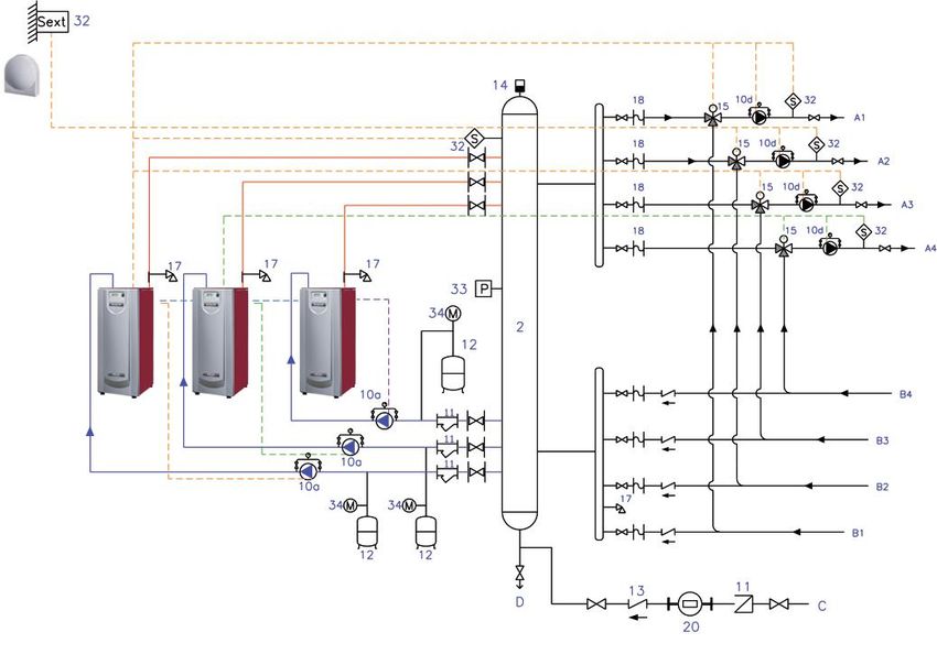
2
INDEX

  1
        HIGH PERFORMANCE BOILERS
        FOR CENTRALISED INSTALLATION       4

  1.1 ADI BOILERS                          8
  1.2 NEO FIRE BOILER                     15
  1.3 REGULATION AND CONTROL              18
  1.4 WALL-MOUNTED CONDENSA PRO BOILERS   21

  2
        HEAT PRODUCTION PREPACKAGED
        EQUIPMENT                         23

  2.1 ROOF TOP                            23
  2.2 MICRO AND MINI ROOF TOP             27
  2.3 TERMI PACK SKID                     30

  3     DOMESTIC HOT WATER                31

  3.1 PLATE HEAT EXCHANGERS               31
  3.2 ADIQUICK                            32
  3.3 DHWS TANKS                          35
   3.3.1   ACUINOX                        35
   3.3.2   HYDRO-V                        36
   3.3.3   INTFIX1-I                      37
   3.3.4   ACFIX1-V and ACFIX2-V          38

  4     ACCESSORIES                       39

  4.1 INERTIAL TANK                       39
  4.2 ADITRAT                             40

        GENERAL TERMS AND CONDITIONS OF
  5     SALE AND WARRANTY                 41

                                               3
1 HIGH PERFORMANCE BOILERS
  FOR CENTRALISED INSTALLATIONS

     MODULATING BURNER
     Special alloy mesh:                                         Variable speed fan                                         MODULATION
                                                                                                                              FROM

                                                                                                                           16%
       • Wide range of power modulation.                         (maximum range).
       • Homogeneous and stable combustion.                      Minimum electrical
       • Fast cooling (low thermal inertia).                     consumption from 17 W.
       • Rapid response to changes in the demand of
         power.
       • High mechanical and thermal resistance.

          Modulation from 16% of the power (NEO FIRE boiler)

     BOILER COMBUSTION SYSTEM
     It includes a modulating burner with maximum performance:                     2                                  Pa

         • Modulation from 16% of the power.                                                            5

         • Variable speed fan (8-9).                                                   8-9
                                                                                                                 13
                                                                                                                                           10

                                                                                                                           Pg
         • Air-gas pre-mix in venturi system (5).                                                                                 15

         • Optimal combustion over the entire modulation range.
                                                                                       B
         • Gas solenoid valve (6) modulates flow according to pressure (13).                 1   6          6b        6a               7

         • Included as standard: “PID” central control (2) for power modulation.

     Minimum electrical consumption.
     Very low noise level.

        Minimum emission of pollutants (complies with requirement 2018, ErP Eco-design Directive).

     MAXIMUM SEASONAL PERFORMANCE

     Minimal thermal losses in readiness for service                       Water flow temperature: constant or in relation to
     (stand-by):                                                           outside temperature.
        • Double insulation: both in boiler body and casing                 Seasonal performance up to 108%
          (medium and high power ADI boilers).                             (according to DIN 4708 part 8).
        • Compact size: minimum loss area.

    House thermal demand                                              Power of heat generation system

4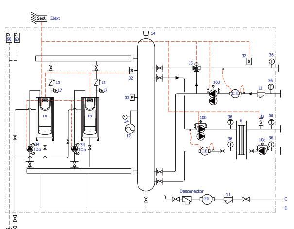
1    HIGH-PERFORMANCE BOILERS
     FOR CENTRALISED INSTALLATIONS

MULTIPLE MANAGEMENT OPTIONS

     External P/M / Alarm / Status                                  Flow temperature function of outside temperature
     • Included as standard on ADI boilers.                         • Example : radiators.
     Constant flow temperature
     • Example: Fan Coils circuit: 45ºC.

                                                                 House thermal demand      Power of heat generation system

                                                                      Webserver
                                                                      • Remote management (PC / Tablet / Smartphone) with
     External signal 0…10 V                                             any internet browser.
     • Boiler flow temperature set point.
             Flow
       temperature
          set point

            F2=85

            F2=65

                                                                      BMS (Building Management System)
                                                                      • Modbus RTU / BACnet.
                                                       Voltage
                    U1=0V   0,15V             U2=10V

INTEGRAL ENERGY EFFICIENCY MANAGEMENT
Integrating into boilers the control set of generators, heating circuits, and DHW in order to optimize the operation to
achieve maximum energy efficiency as a whole.

    Boiler cascade:
      • Based on the demand of the installation.
      • With boilers sequence inversion for equalizing the
        number of hours worked per boiler.
    Control of heating circuits by:
      • 3 ways valve control.
      • Circuit pump control.
      • Hourly/daily programming of each circuit.
      • Set point reductions (night).
    Domestic Hot Water (DHW) control:
      • DHW set point temperatures.
      • Anti-legionella pasteurization and frequency.

                                                                                                                             5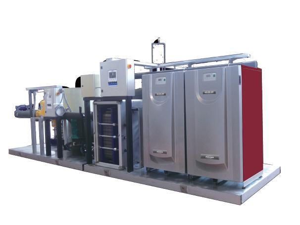
1   HIGH-PERFORMANCE BOILERS
    FOR CENTRALISED INSTALLATIONS

    WEB SERVER: REMOTE MANAGEMENT OF INSTALLATIONS VIA WEB
                                                                                                                VERY EASY TO
                                                                                                              INSTALL AND USE
                                                                                                                 NO SPECIFIC
      New control device that allows the remote monitoring and management of                                      SOFTWARE
      boilers and installations through the usual Internet browsers.

      REMOTE MANAGEMENT OF INSTALLATIONS VIA WEB

      Remote monitoring via computer, smartphone, tablet.                 Sending of breakdowns, reports, and information e-mails.
      Setting of parameters, set points, and information.                 Fast return on investment.
      Preventive and maintenance warnings.

                                           Boilers/installation
                                                                                                    Remote management/emails
                                                                                                      PC/laptop/smartphone

                        USB                   Ethernet
                                                                                 Internet

                                 Web-server

      FEATURES
      Control and monitoring of the installation via web.
      Access for operation via Internet.
      3 different versions (1/4/16 devices):
        • 1 device: 1 boiler, 3 heating circuits and DHW.
        • 4 devices: cascade of up to 4 boilers, 12 heating circuits and DHW.
        • 16 devices: up to 16 boilers and the corresponding circuits.
         Each heating circuit: flow temperature reading, fixed set point or heating curve, schedule program, start/stop pump,
         winter-summer, etc.
      2 configurable digital entries for additional error messages.
      Error messages on the web browser screen.
      Sending error messages to up to 4 email recipients.
      Customization of installation outlines with set points and reading.
      Import of technical documents and creation of links to web pages.
      Several access levels.
      Recording and downloading of historical data on demand.

6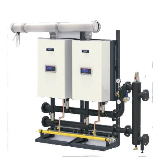
1       HIGH-PERFORMANCE BOILERS
        FOR CENTRALISED INSTALLATIONS

    DISPLAY
      • Up to 19 languages
      • Multiple readings on the same screen

                                                                                    Seasonal
                                                                                    performance up to 108.4 %.

                                                                                               Modulating burner (included)
                                                                                                • Modulates power from 16%
                                                                                                                         MODULATION
                                                                                                                           FROM

    •   ON/OFF                                                                                                           16%
                                                                                                                           NEO FIRE

    •   0...10 V
    •   Modbus RTU                                                                                                   MODULATION
                                                                                                                       FROM

    •   BACnet                                                                                                      23%  ADI

Ecological        MINIMUM                                                         No side maintenance
                    NOx
combustion         Class 6                                                        required
NOx Class 6

 MAIN CHARACTERISTICS                                         PRODUCT ADVANTAGES
 Seasonal performance up to 108.4%.                           High performance and energy savings.
 It includes a modulating burner as of 16% of power:          EC certified.
    • Variable speed fan.                                     Great resistance to corrosion and high temperatures.
    • Modulating gas valve.                                   Minimum sound level:
 Includes management PID control, boiler and power               • Variable speed fan.
 modulation.                                                     • Internal sound-dampening panels.          MINIMUM
 Control of Domestic Hot Water Sanitary (DHW)                 Minimum electrical consumption from 17 W.         NOx
 production, and programming of legionella pasteurization.                                                     Class 6
                                                              Ecological combustion NOx class 6.
 Digital screen (several languages):                          NOx < 10 ppm, CO around 47 ppm.
    • Operation Data.                                         Optimized and reduced dimensions and weights.
    • Messages (error, warnings...).                           Controllable from external control unit: 0...10 V.
    • Multiple readings on screen.                            It complies with the Eco-design Directive.

 OPERATION DATA                                               SAFETY
 Water temperatures:                                          Hydraulic:
    • Maximum flow nominal 86 ºC (up to 90 ºC).                 • Over temperature.
    • Minimum return: NO LIMIT.                                 • Pressure.
 Maximum hydraulic pressure: 5 bar (ADI), 6 bar (NEO FIRE).     • Water flow.
 Natural gas: nominal: 20 mbar, range: 17 to 45 mbar          Gas:
 (lower: request information).                                  • Safety pressure switch.
  Propane gas: request information.                             • Ionisation.
 Electricity:                                                   • Double gas solenoid valve.
    • 230 V, 50 Hz, single-phase + ground.                    Anti-freeze.
    • Over 790 kW: 380 V, 50 Hz, three-phase + ground.

                                                                                                                                      7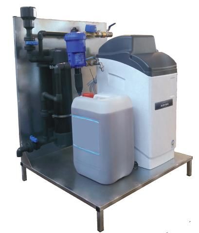
1   HIGH PERFORMANCE BOILERS FOR CENTRALISED INSTALLATIONS
    1.1 ADI BOILERS

    High efficiency gas standing boilers

       ADI
       BOILERS

    MAXIMUM ENERGY EFFICIENCY
    IN MINIMUM SPACE

                               MODEL         POWER (kW)
                                                                     71 –464 kW                                    535 –1,808 kW

                               70 - 475       71.2 - 464
                                                                                  CONDENSING                     CONDENSING

                                                                                 108%
                                                                                  PERFORMANCE
                                                                                                              104% ref. to LCV
                                                                                    SEASONAL                    EC CERTIFICATE

                              550 – 950       535.5 - 905
                                                                                  ADI CD                         ADI LT

                             1200 – 1900     1,210 - 1,808           TECHNICAL                               TECHNICAL
                                                                     DOSSIER                                 DOSSIER
                                                                     ADI CD                                  ADI LT

                                                                                     DOSSIER TÉCNICO   TECHNICAL MANUAL    NOTICE TECHNIQUE
                                                                                     ADI CD ESPAÑOL    ADI CD ENGLISH      ADI CD FRANÇAIS

     High energy efficiency, maximum seasonal                     From 71 to 1,808 kW of power
     performance.
                                                                  In compliance with Eco-design Directive.
     Modulation as of 23% of the power.

       BOILER BODY

       Stainless steel heat exchange body:
         • High resistance to condensate and high temperatures.
         • No return temperature limit.
       Large heat exchange surface
         • Maximum use of the heat from the combustion
           smoke.
       Immediate response to variations in power demand.

8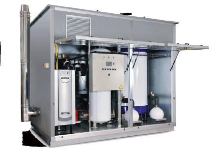
1     HIGH PERFORMANCE BOILERS FOR CENTRALISED INSTALLATIONS
      1.1 ADI BOILERS

COMPACT DIMENSIONS AND                                                  SPACE COMPARISON USED IN A 930 KW BOILER
                                                                        ROOM.
LOW WEIGHTS

     Smaller boiler rooms.
     Space savings.                                                               Traditional type boiler                        ADI boiler

     Lower cost.                                                                                            15.4 m2

                                                                                                                                                6.4 m2
         230 kW in < 0.3 m2       464 kW in < 0.76 m2

                                                                      3825 mm

                                                                                                                      2420 mm
                                                                                                                                       LT 475
                                                                                                                                                         Saving of
            695 kW in 1 m2         904 kW in 1.12 m2                                                                                                       9 m2
                                                                                                                                       LT 475

                     1,808 kW in 2.17 m2                                                     4030 mm                                   2660 mm

    FACILITATES CONVERSIONS IN INSTALLATIONS
    THAT ARE DIFFICULT TO ACCESS.

    Transfer to final location with pallet lorry or similar.             MINIMUM EMISSION OF                                                        MINIMUM
    Cranes with a lower tare.                                                                                                                         NOx
                                                                         POLLUTANTS                                                                  Class 6
    Boilers up to 464 kW facilitate access by
    doors, without having to knock down walls, partitions...             Emissions below the limits set
    Its compact design allows for easy location in rooftop,              by the Eco-design Directive (ErP)
    existing or new building.
    Maintenance on its front that allows to reduce the
                                                                                NOx class 6, NOx < 10 ppm                       CO around 47 ppm
    lateral separation between several boilers.

SAVINGS IN MAINTENANCE OPERATIONS

Quick and easy maintenance.
Shorter times required for the extraction of the burner
and combustion chamber check.
Same setting and operating mode for the 70 kW and the
904 kW boiler.
Many common spare parts for the whole range.

FRONT AND REAR VIEWS

     A, B                                                      C, D

                                                                                                                                                                     9
1 HIGH PERFORMANCE BOILERS FOR CENTRALISED INSTALLATIONS
1.1 ADI BOILERS
OPTIMIZED AND REDUCED DIMENSIONS
ADI CD and LT
A B
H
H
F F
7 7
A
L1
C
H
F
7
A
L1
D
A
H
F
7
L1
ADI MEGA COMPACT SPECIAL ADI BOILERS
E
Note: Add the dimension corresponding to the Silent-Blocks supplied with
the boiler.
101 HIGH PERFORMANCE BOILERS FOR CENTRALISED INSTALLATIONS
1.1 ADI BOILERS
ADI CD - TECHNICAL SPECIFICATIONS
CODE ADI CD MAX. POWER MAX. POWER MIN. POWER WEIGHT A (**) H L1
(1) MODEL OUTPUT OUTPUT OUTPUT WITH
T = 40 OC T = 70 OC T = 30 OC WATER
kW kW kW kg mm mm mm
508403 70 71.2 70.5 21.8 140 350 1,110 595
508404 85 A 86.1 85 26.3 149 350 1,110 615
508405 105 105.6 104 26.1 154 350 1,110 635
508408 120 121.3 120 30.2 169 450 1,110 635
B
508409 175 163.4 161.8 40.6 173 450 1,110 655
508410 200 204.5 197.5 48.9 416 660 1,583 940
508411 250 244.7 241 60.1 440 660 1,583 940
508412 325 C 302.6 294 82.8 552 810 1,583 940
508413 375 358.7 354 95.7 563 810 1,583 940
508414 450 443.5 440 109 578 810 1,583 940
508415 550 535.5 530 173.8 – 230.9 600 1,040 1,628 940
508416 650 605 598 195.2 – 259.4 605 1,040 1,628 940
508417 750 D 682.4 675 220.1 – 292.4 605 1,040 1,628 940
508492 850 802.1 792.7 256.1 709 1,040 1,658 1,083
508493 950 904.1 892.3 380.9 709 1,040 1,658 1,083
510111 1200 1,210 1,196 195.2 – 259.4 1,210 2,004 1,720 940
510112 1600 E 1,604 1,585 256.1 1,418 2,008 1,720 1,083
510113 1900 1,808 1,785 380.9 1,418 2,008 1,720 1,083
(1) Codes for Natural Gas Boilers: For Propane Gas (LPG), up to and including model 550, please specify when ordering.
(*) Minimum gas power adjustable, up to the minimum indicated, at start up, according to the conditions of the installation.
(**) For models with width (A), 810 mm, in case of having to pass through doors with available space below, request information on the boiler disassembly option for easy access.
Diameter F(7): 150 mm (70 to 175 models), 180 mm (200 and 250 models), 250 mm (325 to 450), 350 mm (550 to 950), 2 x 350 (1200 to 1900 models).
WATER AND GAS CONNECTIONS
ADI CD WATER CONNECTION GAS CONNECTION
MODEL
70 3/4”
2" (threaded)
85 – 175 1”
200 – 450 2” 1/2 1” 1/4
550 – 950 4” 2”
1200 – 1900 4 x 4” 2 x 2”
111 HIGH PERFORMANCE BOILERS FOR CENTRALISED INSTALLATIONS
1.1 ADI BOILERS
ADI LT - TECHNICAL SPECIFICATIONS
CODE ADI LT MAX. POWER MIN. POWER WEIGHT A (**) H L1
(1) MODEL OUTPUT OUTPUT WITH
T = 70 OC T = 30 OC WATER
(*)
kW kW kg mm mm mm
508431 105 A 104 26.6 140 350 1,110 595
508432 130 130 33.4 142 450 1,110 595
508443 150 B 149.3 38 156 450 1,110 615
508433 200 190 48.4 175 450 1,110 635
508490 250 230 58.6 406 660 1,583 940
508434 275 262 65.4 435 660 1,583 940
508435 325 C 322 80.9 539 810 1,583 940
508436 400 380 95.9 551 810 1,583 940
508437 475 464 116.9 578 810 1,583 940
508438 550 545 177.9 600 1,040 1,628 940
508439 650 616 200.7 605 1,040 1,628 940
508440 750 D 695 225.4 605 1,040 1,628 940
508441 850 804 259 709 1,040 1,658 1,083
508442 950 905 392.9 709 1,040 1,658 1,083
(1) Codes for Natural Gas Boilers: For Propane Gas (LPG), up to and including model 550, please specify when ordering.
(*) Minimum adjustable gas power up to the minimum indicated at start up according to the conditions of the installation.
(**) For models with width (A), 810 mm, in case of having to pass through doors with available space below, request information on the boiler disassembly option for easy access.
Diameter F(7): 150 mm (105 to 200 models), 180 mm (250 and 275 models), 250 mm (325 to 475), 350 mm (550 to 950).
WATER AND GAS CONNECTIONS
ADI LT WATER CONNECTION GAS CONNECTION
MODEL
105 3/4”
2" (threaded)
130 - 200 1”
250 - 475 2” 1/2 1”1/4
550 – 950 4” 2”
121 HIGH PERFORMANCE BOILERS FOR CENTRALISED INSTALLATIONS
1.1 ADI BOILERS
HYDRAULIC KITS FOR SEVERAL “ADI” BOILERS
FEATURES 1. Boiler (not included).
2. Boiler pump: high-performance (according to Eco-design Directive).
Complete kit of prepared materials for 3. Boiler overpressure safety valve (4 bar).
quick and easy assembly.
4. Anti-return device for the boiler.
They simplify two hours of installation. 5. Boiler cut-off keys.
Compatible with vertical low loss 6i-6r. Flow and return hydraulic manifold . Insulated .
header 7. Low loss header (not included).
Screws and seals.
HYDRAULIC KITS FOR 2 BOILERS
OPTIONAL CONNECTION TO LEFT OR RIGHT HYDRAULIC KIT
For better adaptation in the installation / boiler room according to interest on either side.
CODE MATERIAL DESCRIPTION
Up to 2 ADI CD 175 or ADI LT 200 boilers - Flow and return manifolds: 3”
509560 Kit-Hid-2c-3" (compatible with 6" vertical low loss header)
REVERSIBLE LEFT OR RIGHT
Up to 2 boilers models ADI CD 450 or ADI LT 475 - Flow and return manifolds: 4”
509561 Kit-Hid-2c-4” (compatible with 12" vertical low loss header).
REVERSIBLE LEFT OR RIGHT
Up to 2 boilers models ADI CD 950 or ADI LT 950 — Flow and return manifolds: 6”
510724 Kit-Hid-2c-6"
(to connect to the inertial tank, refer to the price list).
HYDRAULIC KITS FOR 3 BOILERS
CODE MATERIAL DESCRIPTION
From 3 x ADI CD 70 up to 3 ADI CD 175 boilers
Flow and return manifolds: 3"
510725 Kit-Hid-3c-3" (compatible with 6" vertical low loss header)
(Note : for 3 x ADI LT 200, please request information)
REVERSIBLE LEFT OR RIGHT
From 3 x ADI CD 200 up to 3 ADI CD 325 or ADI LT 325 boilers
Flow and return manifolds: 4"
510726 Kit-Hid-3c-4" (compatible with 12" vertical low loss header).
(Non applicable : for 3 x ADI 375 to 3 x ADI 475, please request information)
REVERSIBLE LEFT OR RIGHT
3 x ADI 550 up to 3 ADI 750 boilers
Flow and return manifolds : 6”
510727 Kit-Hid-3c-6”
(to connect to the inertial tank, refer to the price list).
(Non applicable : for 3 x ADI 850 up to 3 x ADI 950, please request information)
The material is supplied disassembled and packed but is assembled at the client's expense.
Boilers (1) not included in the Kits, order additionally.
Vertical low loss header (7): not included, please order additionally
131 HIGH PERFORMANCE BOILERS FOR CENTRALISED INSTALLATIONS
1.1 ADI BOILERS
VERTICAL LOW LOSS HEADER
VERTICAL LOW LOSS HEADER, FOR THE PREVIOUS HYDRAULIC KITS.
Thermal insulation.
Water connection (2 x boilers and 2 x circuit).
Hoses to connect: probes, thermometers, pressure switches, air vent, emptying valve... (material not included.)
Compatible with previous hydraulic kits: easy assembly and mounting.
Facilitates degassing.
CODE MATERIAL DESCRIPTION
To connect to Kit-Hid-2c-3” and Kit-Hid-3c-3”
Connections:
509562 6” LOW LOSS HEADER To boilers: 3" flanges (compatible with Hydraulic Kit)
To circuits: 3” thread
To connect to Kit-Hid-2c-4” and for Kit-Hid-3c-4”
Connections:
509563 12” LOW LOSS HEADER To boilers: 4" flanges (compatible with Hydraulic Kit)
To circuits: 4” thread
To connect to Kit-Hid-2c-3” and Kit-Hid-3c-3”
Connections:
510261 6” SPLIT LOW LOSS HEADER To boilers: 3" flanges (compatible with Hydraulic Kit)
To circuits: 3” thread
To be connect to Kit-Hid-2c-4” and Kit-Hid-3c-4”
Connections:
510614 12” SPLIT LOW LOSS HEADER To boilers: 4" flanges (compatible with Hydraulic Kit)
To circuits: 4” thread
EXAMPLE OF APPLICATION
WITH LOW LOSS HEADER:
DHW production with storage tank.
Pay attention to complete
pressure drops to use the
standard hydraulic kits (request
information on each case).
141 HIGH PERFORMANCE BOILER FOR CENTRALISED INSTALLATION
1.2 NEO FIRE BOILER
Standing gas boiler with high efficiency cast aluminium heat exchanger
NEO FIRE
BOILER
CONDENSATION
108.45%
ref. to LCV
MAIN CHARACTERISTICS
PRODUCT ADVANTAGES
Cast aluminium heat exchanger.
High performance and energy saving.
Power from 80 to 900 kW.
EC certificates (B23).
Performance from 97 to 108.45% ref. to LCV.
NEO FIRE 80 to 280 also certified as watertight
Includes modulating burner from 16% of the power: boilers (C13, C33 and C53; 2 separate tubes).
• Variable speed fan. No minimum return temperature.
• Modulating gas valve. Minimum sound level.
Includes management PID control, boiler and power • Variable speed fan
modulation. • Soundproof panels
Control of domestic hot water production (DHW), Removable panels, easy maintenance.
and programming of legionella pasteurization. Minimum electrical consumption: from 20 W.
Digital screen (several languages): Controllable from external unit: 0...10V.
• Operation Data. Possibility of connecting up to 16 boilers in cascade.
• Messages (error, warnings...). Complies with the Eco-design Directive.
• Multiple readings on screen. Remote management via Modbus protocol (optional).
OPERATION DATA
Water temperatures:
SAFETY Maximum flow: nominal 86ºC (up to 90ºC)
Minimum return: NO LIMIT.
Water: Maximum hydraulic pressure: 6 bar.
• Overtemperature Natural gas: nominal 20 mbar, range 17 to 45 mbar
• Pressure (lower: please, enquire).
• Water flow rate Propane gas: nominal 37mbar, range 25 to 45 mbar
Gas: Electricity:
• Pressure switch minimum • 230 V, 50 Hz, single-phase + ground
• Ionisation • NEO FIRE 810 and 900: 380 V, 50 Hz, three-phase +
• Gas Double Solenoid Valve ground
Anti-freeze
Removable panels for easy maintenance.
Folding front doors.
151 HIGH PERFORMANCE BOILER FOR CENTRALISED INSTALLATION
1.2 NEO FIRE BOILER
NEO FIRE 80-160
NEO FIRE 200-280
CODE NEO FIRE Max. power Max. power Min. power MODULATION Weight without Water content SIZES
MODEL output output output from water
(50-30ºC) (80-60ºC) (50-30ºC)
kW kW kW % kg litres
510897 80 84 78 13 18 158 13
510898 120 126 117 22.7 18 237 15 A
510899 160 168 156 30.2 18 316 18
510900 200 210 195 37.8 18 395 23
510901 240 252 234 45.4 18 474 26 B
510902 280 294.5 273 53 18 553 29
WIDTH LENGTH HEIGHT* Ø smoke Ø water GAS Ø AIR
CONNECTION
mm mm mm mm mm
A 715 1,150 1,320 150 R 2” 1” 110
B 715 1,440 1,320 200 R 2” 1 1/2” 110
* The dimension does not include the height of the anti-vibration feet
161 HIGH PERFORMANCE BOILER FOR CENTRALISED INSTALLATION
1.2 NEO FIRE BOILER
NEO FIRE 360 - 720
NEO FIRE 810 - 900
CODE NEO FIRE Max. power Max. power Min. power MODULATION Weight without Water content SIZES
MODEL output output output from water
(50-30ºC) (80-60ºC) (50-30ºC)
kW kW kW % kg litres
510903 360 376.5 350.5 59.5 16 366 46
510904 450 472.5 438.1 74.4 16 396 52
510905 540 567 525.7 89.9 16 428 58 C
510906 630 661.5 613.4 104.5 16 458 64
510908 720 756 701.0 119.4 16 488 70
510909 810 850.5 788.6 134.4 16 560 91
D
510910 900 945 876.2 149.3 16 630 91
WIDTH LENGTH HEIGHT* Ø smoke Ø water GAS
CONNECTION
mm mm mm mm
C 950 1,730 1,370 250 DN100 PN16 2”
D 950 1,980 1,370 250 DN100 PN16 2”
* The dimension does not include the height of the anti-vibration feet
171 HIGH PERFORMANCE BOILER FOR CENTRALISED INSTALLATION
1.3 REGULATION AND CONTROL
REGULATION
AND CONTROL
OVERALL ENERGY EFFICIENCY MANAGEMENT
Our boilers include an advanced control that manages • It adapts the water temperature to the different
the overall operation of the installation, optimising energy circuits and requirements.
efficiency and reducing fuel consumption: • Heating circuits control (mixing valve and pump.)
• Boilers, installation, and integrated circuits control. • Domestic hot water production and anti legionella
• System of maximum savings and energy efficiency. protection.
• Integrated master-slave type boiler sequence.
• Adaptation to the power required by the installation at
all times.
OPTIONS
CODE MATERIAL IMAGE DESCRIPTION
CASCADE/BOILERS Module OCI345 for boiler cascade with cable and connector
509731
SEQUENCE KIT (1 x boiler)
Module AGU2550 for controlling a heating circuit (mixing valve and
FIRST HEATING CIRCUIT
509516 circulating pump). It includes bus cable AGU2110 between boiler and
KIT extension modules and connectors. Temperature sensors not included.
ADDITIONAL HEATING Module AGU2550for controlling a heating circuit (mixing valve and
509540
CIRCUIT KIT circulating pump) with connectors. Temperature sensors not included.
OUTSIDE TEMPERATURE Outside temperature sensor model QAC34 with temperature
509515
SENSOR range -50...70 ºC with connector (1 x installation or set.)
Flues temperature sensor with sensor device NTC10k and temperature
FLUES TEMPERATURE
509541 range 0... 200 ºC and 1 m of cable length with connector and thread
SENSOR included for installation in the boiler flues output.
Immersion temperature sensor model QAZ36 with sensor device
IMMERSION
509514 NTC10k and temperature range 0...95 ºC, 2 m cable length and
TEMPERATURE SENSOR connector (immersion pocket not included).
BRASS POCKET Chromed brass pocket 100-150 mm long with 1/2” thread for the
509539
150 mm temperature sensor.
STAINLESS STEEL POCKET 100 mm long stainless steel pocket with 1/2” thread
509517
100 mm for temperature sensor.
509564 WEB SERVER 1 BOILER 1 boiler and circuits.
WEB SERVER
509542 Up to 4 boilers and circuits.
4 BOILERS
Module to enable remote management: read/write boiler data via
Modbus RTU protocol (temperatures, setpoints, heating circuits,
510728 MODBUS RTU KIT DHW...)
(1 x boiler)
Fittings are available for remote management, via protocols:
• BACnet
510729 BACnet CONVERSION KIT • Other protocols (request information)
Application of 2 to 4 boilers.
181 HIGH PERFORMANCE BOILER FOR CENTRALISED INSTALLATION
1.3 REGULATION AND CONTROL
Possible uses: Residential buildings,
hotels, hospitals, residences, sports
centers, schools/universities, industries...
Examples of control selection for circuits
2 BOILERS WITH 3 MIXING HEATING CIRCUITS AND DOMESTIC HOT WATER
Maximum energy
efficiency of the set.
UNITS REFERENCE DESCRIPTION
2 BOILER ADI boilers + common manifold/inertia.
OCI345 module for boiler cascade, with cable and connector
2 BOILER CASCADE KIT (1 x boiler).
AGU2.550 module for controlling a heating circuit
1 FIRST HEATING CIRCUIT KIT (mixing valve and pump) Includes bus cable (AGU2.110) between the
boiler and modules and connectors. Temperature sensors not included.
AGU2.550 module for controlling a heating circuit
2 ADDITIONAL HEATING CIRCUIT KIT (mixing valve and pump) with connectors. Temperature sensors
not included.
Immersion temperature sensor model QAZ36 with NTC10k sensing
IMMERSION TEMPERATURE SENSOR
5 sensor device and temperature range 0...95 ºC and 2 m cable and
KIT connector length (immersion pocket not included.)
Outside temperature sensor model QAC34 with temperature range
1 OUTSIDE TEMPERATURE SENSOR KIT -50...70 ºC with connector (1 x installation or set.)
191 HIGH PERFORMANCE BOILER FOR CENTRALISED INSTALLATION
1.3 REGULATION AND CONTROL
EXAMPLES OF ADI BOILERS AND FITTINGS
EXAMPLE A: 2 ADI BOILERS CD 175 AND ALL AVAILABLE ACCESSORIES
UDS. CODE TEAM DESCRIPTION IMAGE
2 508409 ADI CD 175 Condensing boiler.
Hydraulic kit 1, included:
2 Pumps (10a)
4 Shut-off valves
2 Non-return valves (13)
Prefabricated and tailored fitting with all the
1 509560 2 Overpressure valve (17)
necessary parts to receive and assemble.
4 Pressure switches (14)
2 insulated water manifolds
(flow—return)
Tubes, flanges, seals, screws
Low loss header 6’’
1 509562 Fitting designed for sets of 2 boilers.
(insulated)
For several boilers: to operate in cascade or sequence
based on the installation demand, and alternating
operation of boiler hours.
2 509731 Cascade/ Sequence Kit or Module
If a BMS (Building Manage System) control is foreseen
to control the boilers, it is not necessary to offer these
modules.
Flow temperature sensor/ To perform the sequence / cascade of ADI boilers.
1 509514
Common flow Settle in the common flow, see outlines.
To be able to set the common flow temperature
100 mm brass pocket for previous
1 509537 sensor.
probe
Optional : for reading flues temperature.
2 509541 Flues temperature sensor
Serves as a chimney pyrostat, manual reset.
Optional if you want the boilers flow temperature to
1 509515 Outside temperature sensor be a function of the outside temperature (especially
heating circuits).
Optional: if the client wants to monitor, verify, change
1 509542 Web server up to 4 boilers setpoint, alert alarms, and history using the internet
(PC, tablet, smartphone...).
Water treatment of circuit filling.
Offer based on the quality of the network water.
See water quality requirements in ADI's Installation
1 508770 ADITRAT
and Maintenance Manual.
Installer company can install a water treatment
system of a specialized company.
201 HIGH PERFORMANCE BOILER FOR CENTRALISED INSTALLATION
1.4 WALL-MOUNTED CONDENSA PRO BOILERS
High-power wall-mounted condensing boiler
CONDENSA HIGH-POWER
PRO WALL-MOUNTED
HIGH POWER AND
PERFORMANCE
WALL-MOUNTED BOILER
MAIN CHARACTERISTICS PRODUCT ADVANTAGES
Large power range: from 34.4 to 142 kW High Performance.
Gas condensing boiler, including: Very low NOx emission (class 6): according to the
• Modulating burner (variable speed fan). latest application of the Eco-design Directive ErP 2018.
• Depending on the model: boiler water circulation pump. Battery connection of several boilers.
Heat exchanger body: stainless steel AISI 321 and Included as standard:
Stainless steel AISI 316 Titanium • Terminals for external control signal: 0...10 V.
Power modulation: from 20%. • Modbus communication.
Efficiency at maximum power (80-60ºC) up to 98.5%
(ref. to LCV). VERY LOW
NO x
Efficiency at minimum power (30ºC) up to 109.5% Class 6
(ref. to LCV).
It can work as a watertight boiler.
Maximum working hydraulic pressure: 6 bar.
Maximum flow temperature: 80ºC.
Fuel: natural gas or propane.
MULTIPLE BOILERS ARRANGED
IN PARALLEL
Possibility of installing several boilers in parallel, great
variety of fittings to adapt to any situation or controlled
space.
Wall-mounted or in parallel installation using brackets,
either side by side or back to back.
Management of the sequence / cascade of several
boilers that adapts the power supplied by the set to the
variation in the demand of the installation.
Inversion of modules operating sequence.
Constant flow temperature or function of outside
temperature.
211 HIGH PERFORMANCE BOILER FOR CENTRALISED INSTALLATION
1.4 WALL-MOUNTED CONDENSA PRO BOILERS
TECHNICAL SPECIFICATIONS
CONDENSA PRO
MODEL 35 50 57 70 90 100 115 135
CODE 510674 510437 510477 510478 510529 510675 510449 510676
Boiler pump included included included included Not included Not included Not included Not included
Max. power output
kW 38 48.8 61.9 73.9 97.4 105.1 121.1 142.1
(50-30ºC)
Max. power output
kW 34.4 44.2 55.7 67 88.3 95.2 109.8 129
(80-60ºC)
Min. power output
kW 9.9 9.9 14.9 14.9 21.1 21.1 24.5 28.9
(50-30ºC)
Min. power output
kW 8.9 8.9 13.5 13.5 19.2 19.2 22.1 26
(80-60ºC)
Power modulation from % 25.87 20.14 24.24 20,.5 21.74 20.17 20.13 20.16
Weight (without water) kg 65 65 70 70 78 78 90 95
Water content l 5 5 15 15 17 17 23 25
HxLxP mm 1,000 x 600 x 435 1,165 x 600 x 435
Flow circuit, G 1” 1/2 M thread
Return circuit, 1” 1/2 M thread
Gas connection, G 1” M thread
Condensate outlet, 25 mm
EXAMPLE 2 PIPE OR COAXIAL WATERTIGHT BOILER
222 HEAT PRODUCTION PREPACKAGED EQUIPMENT
2.1 ROOF TOP
Heat production prepackaged units, with high efficiency gas boilers, for outdoor installation.
ROOF TOP
CUSTOMISED HIGH POWER
SOLUTION
MAIN CHARACTERISTICS PRODUCT ADVANTAGES
Production of heating and/or D.H.W.S. in centralised Prepackaged solution.
installations. High power outputs (in one casing).
Up to 3,620 kW with gas boilers in one casing. Maximum energy efficiency.
For outdoor installation. Customizable equipment: flexible hydraulic design.
Freestanding structure. Option to include DHW tank.
Sectors: residential, hotel, commercial and service. Compact technology: smaller dimensions and lower
External equipment maintenance. weights in the market.
Compliant with UNE 60.601. Performance and leak tests in factory before delivery.
Savings in costs and installation time.
COST AND INSTALLATION TIME SAVINGS
Allows workload seasonal disaggregation. Fast and safe start up:
Possibility of undertaking several installations at the - Fully connected internal equipment.
same time. - Leak and performance tests on factory before
Single supplier, one delivery time. delivery.
Reduced installation time: After-sales: service level guaranteed by the S.A.T.
- Easy transport and location (freestanding). Official ADISA (SERV-HIPLUS).
- Quick installation: INSTALL AND CONNECT (water, gas
and electricity).
Quality control and comprehensive High power installations for all Easy to transport and install.
performance testing guaranteed in building types.
factory before delivery.
232 HEAT PRODUCTION PREPACKAGED EQUIPMENT
2.1 ROOF TOP
DIMENSIONS AND WEIGHTS
CODE ROOF TOP POWER OUTPUT LENGTH x WIDTH APROX. APROX. MAXIMUM
DIMENSIONS WEIGHT WITHOUT WEIGHT WITH NUMBER OF
MODEL WATER WATER BOILERS
(1) (1)
kW m kg kg
see Micro RT RT0 < 190 0.75 x 1.1 490 570 1
see Mini RT RT1 < 380 1.2 x 1.1 664 793 2
508447 RT2 < 524 1.8 x 1.8 1,300 1,980 2
508448 RT2.5 < 950 2.5 x 1.8 2,300 2,800 2
508449 RT3 < 1,810 3.0 x 1.8 2,950 3,500 2–3
508450 RT3.5 < 1,810 3.55 x 1.8 3,150 4,100 3
508451 RT4 < 2,715 4.2 x 1.8 4,150 5,075 4
508452 RT5.5 < 3,620 5.4 x 1.8 5,180 6,240 4
(1) Approximate weights that may vary according to the internal equipment.
Storage option inside Roof Top equipment with special height boiler casings
or DHW storage directly outside and hydraulically connected to the Roof-Top.
RT2 RT2.5
1,900 1,900 1,900 2,550
1,906
1,906
1,800 1,800 1,800 2,447
RT3 RT3.5
1,900 3,100 1,900 3,653
1,906
1,906
1
1,800 3,000 1,800 3,553
RT5.5
5,489
1,900
1,906
1,800 5,399
242 HEAT PRODUCTION PREPACKAGED EQUIPMENT
2.1 ROOF TOP
ADAPTABLE TO
FLEXIBLE CUSTOMISED DESIGN INSTALLATION
NEEDS
HYDRAULIC
Boilers
• 1 to 4 condensing boilers
Heating
• 1 or multiple circuits.
• Single or double pumps.
• With/without 3-way valves.
• With/without energy meter.
DHW (Domestic Hot Water):
• With/without plate heat exchanger.
• With/without DHW storage tanks
• With/without pumps (single/double)
• Antilegionella prevention.
• With/without energy meter
CONTROL
Internal equipment control: External control, various options:
- Boiler and inversion sequence. • Equipment full external control option, management:
- Optimize energy efficiency pursuant to circuits and uses. - Boilers : 0...10 V per boiler
- Option: double pump cycling. - Pumps, 3-way valves,...
- Antilegionella prevention: pasteurize storage tank. - Global stop/start
• Signals available for the client: • Or:
- Start/stop of equipment. - 1 signal 0...10 V for the boiler assembly
- Unified monitorable - Global start/stop
general alarm. - Pumps, 3-way valves...
• Or:
- Remote management
- Communication/management with protocols:
option: including web server.
Modbus RTU, Modbus TCP/IP, BACnet MS/TP, BACnet IP
Other protocols: please, enquire.
SAFETY
Hydraulic: Lack of water, anti-freeze, overpressure, expansion,
automatic drain...
Gas: detection.
Electrical: electrical cabinet with internal equipment protection
Equipment installed outside the building.
Air vent: the equipment includes large-capacity automatic vents.
Filling: in accordance with current regulations, includes disconnector.
252 HEAT PRODUCTION PREPACKAGED EQUIPMENT
2.1 ROOF TOP
Roof Top Adisa:
Solutions
FOR AN EASIER INSTALLATION Plug & Play
THE MOST COMPACT SIZE AND FREE-STANDING STRUCTURE
WEIGHT IN THE MARKET Equipped with anchor points for lifting with a crane.
Maximum use of the built area.
950 kW on an area of 2.5 x 1.8 m
3,620 kW on an area of 5.4 x 1.8 m
Views of a ROOF TOP equipment with 2 boilers and instantaneous DHW production.
NEW BUILDING RECONVERSION
Easy rooftop installation. Simplify the reconversion of old boiler rooms:
Minimum weight, minimum influence on structural reinforcement. • In the second basement or lower.
Space savings in parking, shops, storage rooms, etc. • Very difficult access.
• Unsuitable flues outlets.
• Forced vents.
262 HEAT PRODUCTION PREPACKAGED EQUIPMENT
2.2 MICRO AND MINI ROOF TOP
Compact heat production prepackaged equipment, with high efficiency gas boilers, for oudoor installation.
MICRO AND
MINI
ROOF TOP
COMPACT SOLUTIONS FOR
EFFICIENT INSTALLATIONS
MAIN CHARACTERISTICS PRODUCT ADVANTAGES
Heating and/or D.H.W.S. production in centralised COMPACT AND COMPLETE SOLUTION
installations.
It includes:
Micro Roof Top:
powers up to 190 kW (1 boiler + 1 pump). Boilers with modulating burner.
Mini Roof Top: powers up to 380 kW. Sequence control (2 boilers).
Up to 2 ADI CD boilers or other ranges. Boiler pump, variable speed.
Reduced sizes and weights: Circuit: hydraulic, gas.
1.2 x 1.1 m. (Mini Roof Top) Safety:
0.75 x 1.1 m. (Micro Roof Top) • Expansion vessel • Lack of water
H: 2 m. • Overpressure valve • Anti-freeze
Freestanding structure. • Gas detection • Electric
Standard configuration: view of boilers from the Electrical cabinet.
front, circuit connections on the right (circuit Lighting.
connections on the left are also available on order). Air shafts.
Equipment tested before supply.
TECHNICAL DETAILS INSTALLATION SAVINGS
Up to 2 ADI boilers (according to ErP Directive). GAS/ECONOMIC SAVINGS
Simple water circulation pump, high performance • Modulating boilers: total adaptation to the
(according to ErP). installation demand variation.
Maximum hydraulic pressure: 4 bar. POWER SAVING
Maximum flow temperature: 85ºC (90 ºC). • High-performance pumps (one per generator) stop
Power supply: 230 V, 50 Hz, single-phase with earth when the boilers do.
connection.
• Low-consumption boilers with variable speed
motor fan (from 48 W).
SPACE-SAVING DESIGN
• Optimized and reduced dimensions and weights.
272 HEAT PRODUCTION PREPACKAGED EQUIPMENT
2.2 MICRO AND MINI ROOF TOP
FREE-STANDING STRUCTURE
MINI ROOF TOP
BASIC CONFIGURATION ADDITIONAL COMPLEMENTS
Up to 2 ADI boilers. Expansion vessel. mRT-E1 vertical low loss header, insulated with
Boiler pump. Temperature sensors. automatic air purge (code 807832.)
Sequence control Gas detection. mRT-E2 Filled circuit.
(case: 2 boilers). Lighting. mRT-E3 Outside temperature sensor.
Circuit flow and return: 3”. External start/stop. mRT-E4 Gas solenoid valve.
Electrical cabinet. Unified alarm signal. mRT-E5 Modbus RTU control.
Overpressure safety Note: for supply of mRT-E1 to E4 specify in order;
External control signal mRT-E1 to E3: supply installed inside the equipment;
valves. available : 0...10 V. mRT-E4: loose supply, to be installed by the client outside the equipment.
MICRO ROOF TOP
BASIC CONFIGURATION CONFIGURATION WITH ALL OPTIONS INCLUDED
OPTIONAL:
LOW LOSS HEADER
OUTSIDE TEMPERATURE SENSOR
FILLING CIRCUIT
GAS SOLENOID VALVE
MODBUS RTU COMMUNICATION
Visit the website,
www.adisaheating.com
to download the models
3D BIM.
282 HEAT PRODUCTION PREPACKAGED EQUIPMENT
2.2 MICRO AND MINI ROOF TOP
TECHNICAL SPECIFICATIONS OF EQUIPMENT WITH ADI CD BOILERS
CODE MINI ROOF TOP POWER OUTPUT BOILERS BASE WEIGHT WITHOUT WEIGHT WITH
MODEL DIMENSION WATER WATER
kW number m kg kg
510125 MICRO RT 70 x 1 CD 70.5 1 0.75 x 1.1 446 512
510126 MICRO RT 85 x 1 CD 85 1 0.75 x 1.1 448 517
510127 MICRO RT 105 x 1 CD 104 1 0.75 x 1.1 459 531
510128 MICRO RT 120 x 1 CD 120 1 0.75 x 1.1 475 547
510129 MICRO RT 175 x 1 CD 161.8 1 0.75 x 1.1 490 570
509012 MINI RT 200 x 1 CD 197.5 1 1.2 x 1.1 665 752
509013 MINI RT 250 x 1 CD 241 1 1.2 x 1.1 686 776
510720 MINI RT 325 x 1 CD 294 1 1.2 x 1.1 781 898
510721 MINI RT 375 x 1 CD 354 1 1.2 x 1.1 791 924
508467 MINI RT 70 x 2 CD 141 2 1.2 x 1.1 576 677
508468 MINI RT 85 x 2 CD 170 2 1.2 x 1.1 580 687
508469 MINI RT 105 x 2 CD 208 2 1.2 x 1.1 602 715
508470 MINI RT 120 x 2 CD 240 2 1.2 x 1.1 634 747
508471 MINI RT 175 x 2 CD 323.6 2 1.2 x 1.1 664 793
EQUIPMENT DIMENSIONS AND VIEWS
MINI ROOF TOP
EXAMPLE MINI RT (1.2 x 1.1 m)
WITH 2 BOILERS:
1. Flues chimneys
2. Water supply: 3" (male thread)
3. Water return: 3" (male thread)
4. Gas : 2" (male thread)
5. Filling
(Power < 150 kW: 3/4", rest: 1")
6. Emptying (DN 32)
7. Condensate drainage
8. Electric connection
9. Gas solenoid valve actuator cables
BASE (A x B): 1,200 x 1,100 mm
BOILER CASING HEIGHT (H): 2,000 mm
EXAMPLE MICRO RT (0.75 x 1.1 m)
WITH 1 BOILER:
MICRO ROOF TOP (I-R) Water return installation:
3" (threaded)
(G) Gas (G): 2"
(V) Emptying : PVC, DN 32
(H) Chimney : isolated, inside diameter:
150
(C) Condensate drainage : PVC, DN 20
(E) Electrical switch, Power
(L) Filling (Power < 150 kW:3/4", rest : 1")
292 HEAT PRODUCTION PREPACKAGED EQUIPMENT
2.3 TERMI PACK SKID
Heat production prepackaged skid with high efficiency gas boilers for installation inside the boiler room.
TERMI PACK
SKID
PREPACKAGED INDOOR SOLUTION
MAIN CHARACTERISTICS PRODUCT ADVANTAGES
Heating and/or DHW production in centralized Prefabricated free-standing solution.
installations. High powers (on one skid).
Up to 3,620 kW on a single skid (extendable through Maximum annual operating performance.
several skids). Customizable equipment: custom design, adapted to
For installation inside a boiler room. every installation and client.
Free-standing structure: includes all necessary Compact technology: most reduced dimensions and
elements (boilers, pumps, gas, electric elements, weights of the market.
controls, securities.)
Leak tester in the factory before their supply.
Sectors: residential buildings, public centres, office
Simplicity of start up and safety of operation.
buildings, hotels, shopping centres, hospitals, etc.
CODE TERMI PACK POWER LENGTH x
OUTPUT WIDTH
OPERATION DATA MODEL DIMENSIONS
kW m
Power supply: three-phase, 380 V, neutral and ground,
or 220 V, single-phase, neutral and ground. 509048 TERMI PACK 0 < 380 1.2 x 1.1
Fuel: natural gas or propane.
509006 TERMI PACK 2 < 464 1.8 x 1.8
Hydraulic pressure: 4 kg/cm2(higher pressures:
request information). 509007 TERMI PACK 2.5 < 950 2.5 x 1.8
The boiler room where the skid is located must comply
509008 TERMI PACK 3 < 1,810 3.0 x 1.8
with the rules and regulations in force.
The air shafts (responsibility of the installer company) 508456 TERMI PACK 3.5 < 1,810 3.55 x 1.8
must comply with the current regulations.
508457 TERMI PACK 4 < 2,715 4.2 x 1.8
509009 TERMI PACK 5.5 < 3,620 5.4 x 1.8
303 DOMESTIC HOT WATER (DHW)
3.1 PLATE HEAT EXCHANGERS
Detachable plate heat exchangers to transfer heat between two circuits.
PLATE HEAT
EXCHANGERS
DIMENSIONS
MODEL A B C MAX. D D D E F I
mm mm mm mm mm mm mm mm mm
IT021 320 200 88 170 ( < 30 plates) 270 ( < 50 plates) 470 ( < 72 plates) 230 68 45
IT042 470 200 88 170 ( < 30 plates) 270 ( < 50 plates) 470 ( < 72 plates) 380 68 45
IT082 755 200 88 170 ( < 30 plates) 270 ( < 50 plates) 470 ( < 72 plates) 665 68 45
IT126 819 310 118 465 (< 72 plates) 605 (< 102 plates) 835 ( < 152 plates) 603 123 128
IT165 1,050 310 88 320 ( < 42 plates) 460 ( < 72 plates) 600 ( < 102 plates) 750 140 170
IT300 1,080 530 101 740 (< 102 plates) 1,240 ( < 202 plates) Enquire 705 250 198
MODELS IT021, IT042 and IT082 MODELS IT126 and IT165 MODEL IT300
TECHNICAL SPECIFICATIONS
MODEL AREA DIMENSIONS PLATE WEIGHT PLATE TYPE RANGE OF HYDRAULIC MAX. Nº
HEIGHT x WIDTH POWER CONNECTION PLATES
APROX.
m2 mm kg kW mm number
IT021 0.021 305 x 145 0.21 Unique < 155 DN 32 stainless steel 71
IT042 0.041 457 x 145 0.32 Unique < 317 DN 32 stainless steel 71
IT082 0.081 740 x 145 0.45 Unique < 520 DN 32 stainless steel 71
IT126 0.125 723 x 245 0.70 A and B < 1,500 DN 65 stainless steel 151
IT165 0.164 857 x 245 0.86 A and B < 1,800 DN 50 stainless steel 151
IT300 0.268 877 x 425 1.67 A and B < 4,000 DN 100 flange 401
313 DOMESTIC HOT WATER (DHW)
3.2 ADIQUICK
Instantaneous DHW production with exact temperature regulation
ADIQUICK
LEGIONELLA LIMIT
MAIN CHARACTERISTICS PRODUCT ADVANTAGES
Precise electronic control to provide instant DHWS of Plug & Play solution, reducing electrical and probe
up to 125 l/min. connection times.
Physical barrier between generation and consumption. Compact technology: The most highly reduced
Without accumulating DHW and controlling dimensions and weights on the market.
recirculation, it eliminates the proliferation of legionella. Boiler casing with thermal insulation in EPP, optimum
Speed control of high-performance pumps (primary and efficiency, and stainless steel pipes.
recirculation). Very low primary returns improve the layering of the inertial
Pt1000 probes with an tank and the performance of a solar thermal system.
accuracy to 1ºC. Integrated, user-friendly electronic control, in graphic
Facilitates cascade operation, environment for convenient monitoring.
and is able to cover even Historical data record and usage charts.
greater DHW demands. Control with multiple base hydraulic variants, adaptable
to each installation.
Different programmable operation modes: Anti-
calcification, recirculation, anti-scalding, anti-legionella,
etc.
INTEGRATED ELECTRONIC REGULATION
PRODUCT ADVANTAGES
Intuitive handling control with only 4 keys.
Monitoring of the current status and recording of statistical data in a graphic environment.
Setting help guide.
10 hydraulic variants configurable in each case.
Clock with 24h post-cut autonomy.
Weekly calibration of the recirculation flow.
Possible menu blockage (against modifications).
5 programs for the recirculation of DHWS
Mixture temperature in primary for min/max demand.
DHW output temperature for min/max demand.
Anti-calcification function, recirculating through the heat exchanger between 5 and 30 seconds after each demand.
Anti-block protection through the timely activation of valves and pumps.
Bus connection for cascade control of several ADIQUICK modules.
323 DOMESTIC HOT WATER (DHW)
3.2 ADIQUICK
COMPONENTS
1 Welded stainless steel plate heat exchanger
2 Primary pump
3 3-way (0-10 V) rapid-action mixer
Except for models 28 and 19 which instead have a non-return valve
4 Recirculation pump
5 DHWS output probe
6 Primary drive probe (mixed)
7 Primary drive probe (inertia)
8 Recirculation probe
9 Purging
10 Non-return valve
11 CWS flow sensor at 40 l/pulse
12 Emptying
13 Shut-off valve
14 Regulation
A DHW output
B Inertia tank probe
C Recirculation return
D Return to the inertia tank
E Cold water connection
FUNCTIONAL DESCRIPTION
The equipment reads the flow rate (11) being consumed at any given time in order to adjust the speed of the primary
pump (2). The DHWS outlet temperature (5) is set, as is the outlet temperature of the mixing valve (6) to limit possible
calcification in the heat exchanger (1). At the same time, it has a variable variable flow rate pump (4) that enables the
return temperature (8) to be set, and thermal shocks to be programmed to clean the legionella circuit.
DHW
BOILERS
INERTIA
SOLAR
INERTIA
SOLAR
PRIMARY
CIRCUIT OR ITS
ALTERNATIVE
333 DOMESTIC HOT WATER
3.2 ADIQUICK
ELECTRONIC ADIQUICK
Secondary ∆T = 50ºC (10 → 60°C) ADIQUICK 120 ADIQUICK 100
Primary probe temp. ºC 65.0 70.0 75.0 80.0 85.0 65.0 70.0 75.0 80.0 85.0
Primary return temp. ºC 32.3 27.9 25.5 22.9 20.5 35.2 31.0 28.4 25.1 22.6
DHW flow rate l/min 79.0 101.0 120.0 125.0 125.0 64.0 84.0 100.0 100.0 100.0
DHW Power kW 273.0 350.0 415.0 432.0 432.0 224.0 291.0 346.1 346.1 346.1
Primary flow rate l/h 7,400 7,400 7,400 6,710 5,970 6,600 6,600 6,560 5,590 4,932
Secondary head loss bar 0.24 0.36 0,.0 0.55 0.55 0.21 0.34 0.46 0.46 0.46
Mixed maximum flow rate (38°C) l/min 141 180 214 223 223 114 150 179 179 179
Instant showers No. 12 15 18 19 19 10 13 15 15 15
Connections
1” 1/4 - 1” 1/2 1” 1/4 - 1” 1/2
(Recirculation - Rest)
Dimensions 1,137 x 600 x 340 1,137 x 500 x 340
Code 510631 510632
Secondary ∆T = 50ºC (10 → 60°C) ADIQUICK 28 ADIQUICK 19
Primary probe temp. ºC 65.0 70.0 75.0 80.0 85 65.0 70.0 75.0 80.0 85
Primary return temp. ºC 35 31 28 26 25 46 43 41 39 38
DHW flow rate l/min 18 24 28 32 36 11 15 19 22 26
DHW Power kW 63 82 98 112 126 37 52 65 78 89
Primary flow rate l/h 1,862 1,862 1,862 1,862 1,862 1,787 1,787 1,787 1,787 1,787
Secondary head loss bar 0.15 0.15 0.15 0.15 0.15 0.15 0.15 0.15 0.15 0.15
Mixed maximum flow rate (38°C) l/min 32 43 50 57 64 17 27 34 39 46
Instant showers No. 3 4 4 5 5 2 2 3 3 4
Connections 1” 3/4”
Dimensions 890 x 500 x 340 660 x 455 x 215
Code 510633 510634
CASCADE CONNECTION
MODEL MAXIMUM MAXIMUM:
CASCADE UNITS
ADIQUICK 120 & 100
kW — l/min
ADIQUICK 120 & 100
ADIQUICK 120 5 2,160 kW — 625 l/min
ADIQUICK 120 & 100
ADIQUICK 100 5 1,730 kW — 500 l/min
ADIQUICK 120 & 100
ADIQUICK 28 4 504 kW — 144 l/min
6 9 5
3
2
B S S A
CODE DESCRIPTION APPLIES TO 8
MODELS
10
4
D S C
1
11 E
DN40 solenoid valve for
510635 120 & 100
cascade control
ADIQUICK 120 & 100
DN25 solenoid valve for 6 5
510636 28 3 9
2
cascade control
B S S A
10 8
4
*As many valves as cascade D S C
equipment are required (see outline). 1
11 E
343 DOMESTIC HOT WATER
3.3 DHW TANKS
3.3.1 ACUINOX
DHW Stainless steel vertical tank
ACUINOX
THERMAL INSULATION AND
MAIN CHARACTERISTICS FINISH
Volumes available: 500 - 5,000 litres (lower ones on request) Complies with the European Eco-design
Stainless steel storage body, AISI 316L Directive (minimum thermal losses).
Maximum working temperature: 90°C
Maximum working pressure: 8 bar
Manhole: DN 400 (for 1,000 litres and above)
Insulation:
• Option A: Flexible PU, thickness : 50 mm
• Option B: Flexible PU, thickness: 100 mm
Warranty: 5 years (see warranty terms)
Includes cathodic protection anode with Magnesium rod.
ACUINOX DE (*) H BR CODE CODE
MODEL Option A Option B
litres mm mm
500 800 1,750 DN 200 510467 510650
750 800 2,000 DN 200 510645 510651
1000 930 2,050 DN 400 510531 510652
1500 1,140 2,100 DN 400 510646 510653
2000 1,300 2,150 DN 400 510647 510654
2500 1,400 2,200 DN 400 510599 510655
3000 1,500 2,300 DN 400 510583 510656
4000 1,600 2,850 DN 400 510648 510657
5000 1,750 2,900 DN 400 510649 510658
(*) DE: External Diameter Option A: insulation thickness 50 mm.
For Option B: add 100 mm to the DE values.
353 DOMESTIC HOT WATER (DHW)
3.3 DHW TANKS
3.3.2 HYDRO-V
DHWS Vertical vitrified steel tank.
HYDRO-V
MAIN CHARACTERISTICS SUPPLY
The optimal solution against corrosion: vitrified Includes:
interior surface treatment, inorganic carbon-free Vertical steel storage tank with inner vitrified
component, made according to regulation DIN 4753-3 to treatment.
850 0C. Cathodic protection anode (Mg).
Storage tank insulation.
Available volumes: 500 to 2000 litres.
Maximum working temperature: 900C.
Maximum hydraulic pressure: 8 bar.
Manhole: every storage tank include it as standard. For
volumes above 800 litres, DN 400.
Insulation:
-Up to 500 litres, injected PU, skay finish
-Superiors: flexible PU, skay finish.
Includes: Cathodic protection anode (Mg).
CODE HYDRO-V DIAMETER HEIGHT BR
(DE) (H)
MODEL
litres mm mm
509675 500 750 1,710 DN 100
509676 750 990 1,940 DN 100
509677 1000 1,050 2,010 DN 400
509678 1500 1,200 2,200 DN 400
509679 2000 1,300 2,400 DN 400
363 DOMESTIC HOT WATER (DHW)
3.3 DHW TANKS
3.3.3 INTFIX1-I
DHWS Stainless steel tank with internal coil
INTFIX1-I
THERMAL INSULATION
MAIN CHARACTERISTICS AND FINISH
Available volumes: 500 - 5.000 litres Complies with the European
(smaller sizes: request information) Eco-design Directive (minimum
Stainless steel body, AISI 316L thermal losses).
Maximum working temperature: 90°C
Maximum working pressure: 8 bar
Manhole: DN 400 (for 1,000 litres and above)
Stainless steel fixed heat exchange coil, for primary circuits
with heat generation.
Insulation:
• Option A: Flexible PU, thickness : 50 mm
• Option B: Flexible PU, thickness: 100 mm
Warranty: 5 years (see warranty conditions)
Includes cathodic protection anode with Magnesium rod.
INTFIX1-I DE (*) H BR Power output CODE CODE
MODEL
litres mm mm (DN) (kW) (**) Option A Option B
500 800 1,750 200 40 - 45 510659 510665
750 800 2,000 200 64 - 80 510660 510666
1000 930 2,050 400 79 - 98 510661 510667
1500 1,140 2,100 400 94 - 114 510662 510668
2000 1,300 2,150 400 112 - 137 510512 510669
2500 1,400 2,200 400 131 - 160 510600 510670
3000 1,500 2,300 400 150 - 183 510584 510671
4000 1,600 2,890 400 169 - 206 510663 510672
5000 1,750 2,935 400 187 - 229 510664 510673
(*) DE: External Diameter Option A: insulation thickness 50 mm.
For Option B: add 100 mm to the DE values.
(**) Refer to the technical data sheet: temperature conditions, secondary, primary, flows...
373 DOMESTIC HOT WATER (DHW)
3.3 DHW TANKS
3.3.4 ACFIX1-V and ACFIX2-V
DHWS vertical vetrified steel tank with 1 or 2 fixed heat exchange coils
ACFIX1-V
ACFIX2-V
MAIN CHARACTERISTICS
Optimal solution against corrosion: Vitrified interior Maximum continuous working temperature: 90º C.
surface treatment, inorganic carbon-free component Working pressure: DHW = 8 bar, Coil = 6 bar.
made according to regulation DIN 4753-3 to 850 0C. The supply includes a magnesium anode for protection.
Available volumes: 200 – 2000 litres. Insulation:
Storage tank: inner vitrified steel. • 500 litres: PU injected, skay finish.
Buffer vessel with manhole. • Rest: flexible PU, skay finish.
Fixed heat exchange coil for primary circuits with sun, It complies with the European Eco-design Directive
generators or boilers. (thermal losses).
Bottom coil: possible use with solar energy or similar.
Top coil: to connect other energies.
CODE ACFIX1-V DIAMETER HEIGHT MANHOLE POWER
(DE) (H) COVER OUTPUT DE
MODEL
litres mm mm DN kw (*)
509698 200 600 1,200 100 36
509699 300 650 1,420 100 48
509700 500 750 1,710 100 66
509701 750 990 1,940 100 93
H
509702 1000 1,050 2,010 400 111
509703 1500 1,200 2,200 400 158
509704 2000 1,300 2,400 400 225
(*) Primary temperature: 90-70 0C, secondary temperature: 10-45 0C.
384 ACCESSORIES
4.1 INERTIAL TANK
Tank for primary circuits of heat generators or primary solar circuits.
INERTIAL TANK
MAIN CHARACTERISTICS PRODUCT ADVANTAGES
Tank made of steel plate. Low loss header.
Available volumes; from 100 to 5,000 litres It increases the thermal inertia in those circuits which
(or balancing manifolds). need it:
Includes thermal insulation. • Energy accumulation in the case of solar collectors.
Maximum working pressure: 6 bar • The heat generators work with longer start/stop time
(higher pressures: request information). ranges.
Maximum temperature: 90 ºC. • Depending on the distribution of connections, it will
Connections: act as a degasser.
• Flanges from 2" to 6" (other dimensions: request information).
• Number of flanges, dimensions and distribution
according to the needs of each installer or engineering.
LOW LOSS HEADER, INSULATED
CODE DESCRIPTION CONNECTIONS
Vertical low loss header 6"
To boilers: 3" (flanges)
509560 Up to 1 ADI CD 175 or ADI LT 200 boiler
To circuit: 3" (thread)
Up to 2 ADI CD 175 or ADI LT 200 boilers
Low loss header 12" To boilers: 4" (flanges)
509561 Up to 1 ADI CD 450 or ADI LT 475 boiler To circuit: 4" (thread)
Up to 2 ADI CD 450 or ADI LT 475 boilers
BUFFER TANK: MEDIUM/LARGE SIZE
TABLE 1 TABLE 2
CODE MODEL DIAMETER (D) HEIGHT (H) CODE FLANGES
litres mm mm
508972 100 550 1,000 809573 2”
508973 200 550 1,510 809574 2” ½
508974 300 600 1,870 809575 3”
508975 500 700 1,910 809576 4”
508976 750 930 1,850 809577 5”
508977 1000 950 2,100 809578 6”
508978 1500 1,280 1,900
508980 2000 1,300 2,400
508981 2500 1,510 2,100
508982 3000 1,510 2,500
508983 4000 1,910 2,200
508984 5000 1,910 2,700
394 ACCESSORIES
4.2 ADITRAT
Equipment for the chemical treatment of filling water for closed heating and/or air conditioning circuits.
ADITRAT
FILLING WATER
TREATMENT
MAIN CHARACTERISTICS PRODUCT ADVANTAGES
Dimensions: base 800 x 680 mm, height 1,050 mm. It prevents the formation of oxide, sludge, calcifications
Min/max pressure: 2-4 bar or scaling, etc., and therefore, it also prevents
Maximum temperature: 45 ºC. premature deterioration of the entire installation.
Min/Max flow rate: 20-1,500 litres/hour. Assembled set fixed on a base. Easy installation,
operation and maintenance.
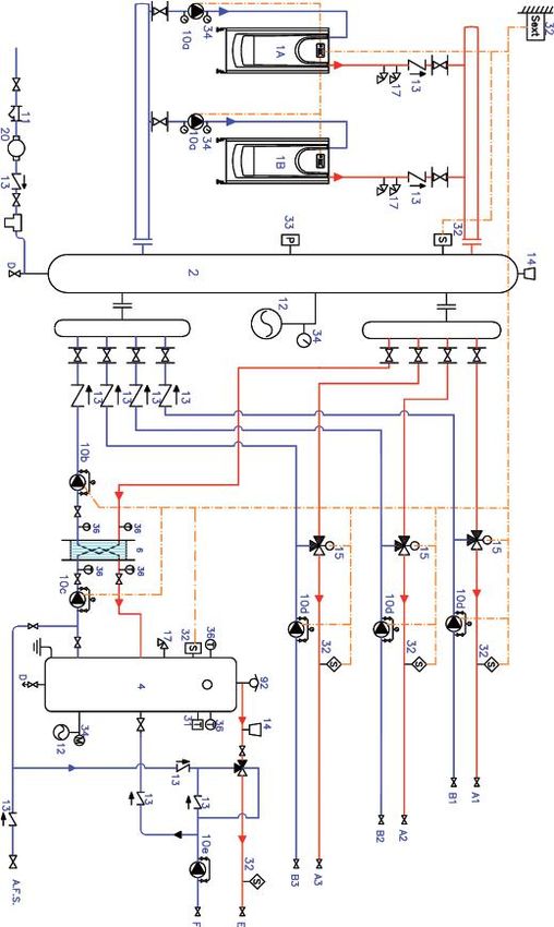
OUTLINE
1. PRESSURE REGULATOR + FILTER
2. WATER SOFTENER
3. CORROSION INHIBITOR DISPENSER
4. QUICK PRODUCT FILLER TANK
5. WATER METER
6. NON-RETURN VALVE
7. CUT-OFF VALVES (CONNECTION ¾”)
A. WATER INPUT
B. INSTALLATION CONNECTION
C. CHEMICAL INPUT
D. EMPYING
CODE MODEL
508770 ADITRAT
Includes: corrosion inhibitor product (27 kg), salts for the water softener (25 kg).
405 GENERAL TERMS AND CONDITIONS OF SALE AND WARRANTY
GENERAL TERMS AND 2. No order cancellations shall be accepted once it has been
accepted by Hiplus, unless there is express consent by
CONDITIONS Hiplus. If authorized, Hiplus reserves the right to charge
1. These General Terms and Conditions are applicable to the client for costs incurred.
all sales made by HIPLUS AIRE ACONDICIONADO S.L. 3. Any amendment of the order shall be made in writing
(hereinafter HIPLUS), with registered offices at C/ Masía and with the acceptance of both parties in order to take
Torrents 2 08800 Vilanova i la Geltrú, Barcelona, and Tax effect.
code number B 86.435.658.
2. These General Terms and Conditions regulate the sale and DELIVERY DATE
technical assistance service of heating equipment sold 1. The delivery date given in the offers and quotes is
under the brand name ADISA Heating Series by Hitecsa approximate and no damage, injuries, fine or compensation
(hereinafter ADISA) by HIPLUS, and will be considered shall be awarded to the client in the event of delay by
known and accepted by the purchaser when placing the Hiplus for whatever reason.
order. These conditions shall be fully applicable unless a 2. The delivery date refers to the date on which the
written derogation is made by HIPLUS. products leave the factory. If the purchaser specifies a
3. The term CLIENT refers to the natural or legal person delivery date in the order and it is impossible to stick to
with whom HIPLUS signs a purchase agreement on the scheduled date, 30 calendar days after, the storage
equipment/s or the provision of technical assistance costs will be charged at the rate of 5 euros per m2 of
services. Likewise, PRODUCTS refers to the heating occupied space and week.
equipment sold by HIPLUS to the client.
4. These Terms and Conditions of Sale replace those DELIVERY CONDITIONS
previously published in the different commercial 1. Deliveries shall be made on-site by lorry in Spanish territory
brochures of the ADISA brand. and in the Peninsula, provided that there are no considered
accessibility problems. Those permits and licenses that
PROPOSALS AND ORDERS were necessary for this purpose shall be borne by the client.
1. The commercial proposals are valid for two months as of 2. Deliveries shall be made during business hours and on
the date they were submitted to the client.. working days.
2. Orders must be placed in writing, bear the signature of 3. The products shall be delivered in standard packaging, the
the client and the stamp of the company (in the case of price of which is included in the sales price.
a legal person) and refer to Hiplus' offer or quote. By 4. The client is responsible for the proper environmental
submitting the purchase order, these General General management of waste from the packaging and containers
Conditions of Sale are deemed to be accepted, and supplied with the products.
acceptance of the order by Hiplus is required in order
to proceed with the execution of the order. Hiplus shall SHIPPING COST
not be liable for any errors or mistakes made by the 1. As of the minimum of €300 (only for materials included
purchaser in the order. in this price list), the price list includes freight prepaid
to the site on a lorry, throughout all of peninsular Spain,
MODIFICATIONS, RETURNS AND without unloading.
ORDER CANCELLATIONS 2. When purchasing goods from Hiplus, shipping costs are
1. No changes or returns of products shall be accepted borne by the purchaser, and any damage to the packaging
once they have been dispatched unless it is so expressly must be claimed to the carrier by including the details of
authorised by Hiplus in writing. In the event that this such damage on the delivery note.
is authorized, the client shall bear all shipping costs
incurred and it shall be understood that the products are
CLAIMS ON GOODS DELIVERED
1. Any claim made after the 10-day period following the
in a perfect state of preservation and packaging. Hiplus
delivery of the material shall not be responded to.
reserves the right to make a charge for depreciation and
2. If any damage to the packages is observed at the time of
the costs of receipt, inspection, and repair of returned
delivery, it shall be indicated on the delivery note of the
products. Once the condition of the product has been
carrier, so that the appropriate claims can be made.
checked and it has been verified that there is no damage,
Hiplus shall proceed with the reimbursement, applying
the corresponding depreciation and handling costs to be
determined by the Sales Department, once the return has
been approved. If any damage is found, the corresponding
amount for repair or reconditioning for sale shall be
deducted from the total to be reimbursed.
41You can also read