Emergency Response Guide - CROSSTREK Hybrid Hybrid 2019 Model - NFPA
←
→
Page content transcription
If your browser does not render page correctly, please read the page content below
CROSSTREK Hybrid
Hybrid 2019 Model

     Emergency Response Guide

                             © 2018 SUBARU CORPORATION
                                                                        Publication No. V1360BE
                       All rights reserved. This document may not be
                                                                        Issued: October 2018
                    altered without the written permission of SUBARU.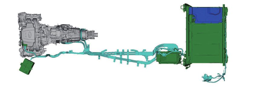
Foreword

SUBARU released the 2019 CROSSTREK gasoline-electric plug-in hybrid vehicle in North America in late 2018.
SUBARU has prepared this Emergency Response Guide to educate and assist emergency responders in the safe
handling of the CROSSTREK Hybrid technology.
Except where noted in this guide, the basic vehicle system and features for the CROSSTREK Hybrid are the same
as those on the conventional, non-hybrid CROSSTREK.
High voltage electricity powers the drive motor, generator, electric compressor assembly, and inverter with
converter assembly. All other automotive electrical devices such as the headlights, radio, and gauges are
powered from a separate battery (12 V). Numerous safeguards have been designed into the CROSSTREK Hybrid
to help ensure the high voltage, approximately 351.5 Volt, Lithium-ion (Li-ion) battery is kept safe and secure in
an accident.
The CROSSTREK Hybrid utilizes the following electrical systems:
   • Nominal 351.5 Volts DC
   • Nominal 12 Volts DC
CROSSTREK Hybrid Features:
   • An electric vehicle charger cable assembly rated at 120 Volts.
   • An onboard battery charger with a 120 Volt /240 Volt AC input and 351.5 Volt DC output.
   • A boost converter in the inverter with converter assembly that boosts the available voltage to the
      drive motor to 650 Volts.
   • An HV battery rated at 351.5 Volts.
   • A high voltage drive motor rated at 351.5 Volts.
   • A high voltage motor driven electric compressor assembly rated at 351.5 Volts and remote climate
      control system.
   • A body electrical system rated at 12 Volts, negative chassis ground.
   • Supplemental Restraint System (SRS) - frontal airbags, a driver knee airbag, front seat side airbags,
      side curtain airbags and seat belt pretensioners.
   High voltage electrical safety remains an important factor in the emergency handling of the
   CROSSTREK Hybrid. It is important to recognize and understand the disabling procedures and
   warnings throughout this guide.
Additional topics in this guide include:
   • CROSSTREK Hybrid identification.
   • Hybrid system component locations and descriptions.
   • Extrication, fire, recovery, and additional emergency response information.

                                                        -i-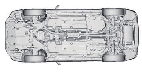
Foreword (Continued)
2019 Model Year CROSSTREK Hybrid
• Roadside assistance information.
This guide is intended to assist emergency
responders in the safe handling of a CROSSTREK
Hybrid vehicle during an incident.
Emergency Response Guides for SUBARU hybrid
vehicles may be viewed at:
PHEV002 [U.S.A]
http://techinfo.subaru.com
-ii-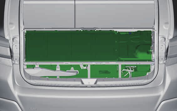
Table of Contents

                                                       Page

About the CROSSTREK Hybrid                              1

CROSSTREK Hybrid Identification                         2

Hybrid System Component Locations & Descriptions        6

Keyless Access with Push-button Start System            10

Hybrid System Operation                                 16

HV Battery                                              19

Plug-In Charge System                                   21

Remote Climate Control System                          24

Low Voltage Battery                                    26

High Voltage Safety                                    27

Plug-In Charge Safety                                  29

SRS Airbags & Seat Belt Pretensioners                  32

Emergency Response                                     35
   Extrication                                         36
   Fire                                                 51
   Overhaul                                            52
   Recovering/Recycling of HV Battery                  55
   Spills                                              55
   First Aid                                           56
   Submersion                                          57

Roadside Assistance                                    58

High Voltage Caution Label                             68

                                               -iii-
About the CROSSTREK Hybrid

The CROSSTREK Hybrid is the gasoline-electric hybrid vehicle for SUBARU. Two power sources are stored
on board the vehicle:

1. Gasoline stored in the fuel tank for the gasoline engine.
2. Electricity stored in a large capacity externally chargeable high voltage HV battery for the drive motor.

Depending on the driving conditions one or both sources are used to power the vehicle. The following
information explains how the CROSSTREK Hybrid operates in various driving modes.

Plug-In EV (Electric Vehicle) Mode:
(1) Utilizing the electric vehicle charger cable assembly connected to a 120 Volt outlet, the vehicle’s HV
    battery can be charged within 5 hours.
    If a 240 Volt outlet is used, the HV battery can be charged within approximately 2 hours.

(2) When the HV battery is sufficiently charged, the vehicle will fundamentally operate in EV mode for
    approximately 17 miles (28 km).

(3) If the vehicle exceeds approximately 65 mph (105 km/h) or accelerates suddenly when traveling in EV
    mode, the gasoline engine and drive motor work together to power the vehicle.

When the HV battery is discharged the vehicle operates in HV mode
HV (Hybrid Vehicle) Mode:
(4) During light acceleration at low speeds, the vehicle is powered by the drive motor. The gasoline
    engine is shut off.

(5) During normal driving, the vehicle is powered mainly by the gasoline engine. The gasoline engine
    also powers the generator to charge the HV battery.

(6) During full acceleration, such as climbing a hill, both the gasoline engine and the drive motor power
    the vehicle.

(7) During deceleration, such as when braking, the vehicle regenerates kinetic energy from the wheels to
    produce electricity that charges the HV battery.

(8) While the vehicle is stopped, the gasoline engine and drive motor may be off, however the system
    remains on and operational.
    Note:
    While the vehicle is stopped, the gasoline engine may restart depending on conditions.

                                                     -1-
CROSSTREK Hybrid Identification
In appearance, the 2019 model year CROSSTREK Hybrid is nearly identical to the conventional, non-hybrid
SUBARU CROSSTREK. The CROSSTREK Hybrid is a 5-door Sports Utility Vehicle (SUV).
Exterior, interior, and engine compartment illustrations are provided to assist in identification.
The alphanumeric 17 character Vehicle Identification Number (VIN) is provided in the front windshield
and passenger side floor.
Example VIN: JF2GTD-XXXXXX
CROSSTREK Hybrid is identified by the first 6 alphanumeric characters JF2GTD.
Driver Side Windshield and Passenger Side Floor
PHEV003
-2-CROSSTREK Hybrid Identification (Continued)
Exterior
① logo on the right side of the rear gate.
② logo on each front fender.
Exterior Front and Rear View
2
1
PHEV006
-3-CROSSTREK Hybrid Identification (Continued)
Interior
③ Combination meter (hybrid READY indicator light) located in the dash behind the steering wheel.
Interior View
3
PHEV007
Combination Meter
Hybrid READY Indicator Light
PHEV008
The illustration above is a typical example. For some models, the combination meter may be slightly
different than that shown in the illustration.
-4-CROSSTREK Hybrid Identification (Continued)
Engine Compartment
④ 2.0-liter aluminum alloy gasoline engine.
⑤ PLUG-IN HYBRID Logo on the engine cover.
Engine Compartment View
4 5
PHEV009
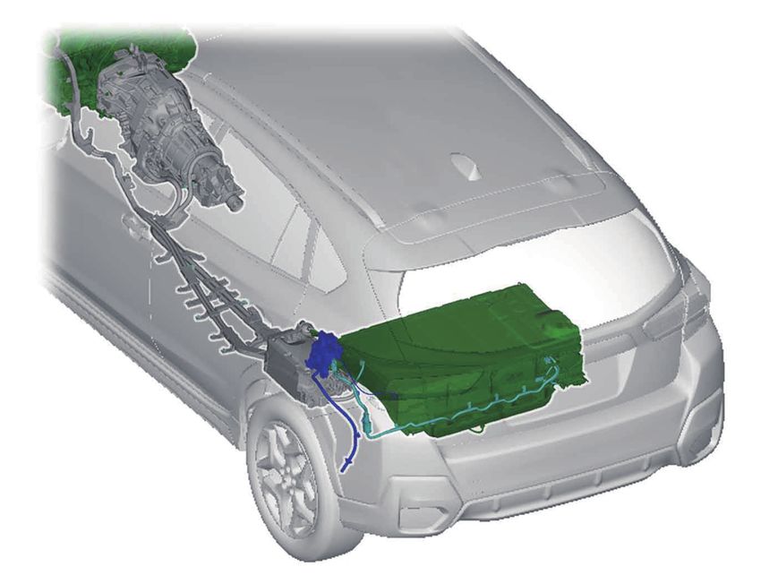
-5-Hybrid System Component Locations & Descriptions
Component Location Description
① Battery (12 V) Engine Compartment A lead-acid battery that supplies power to the low voltage
devices.
② HV Battery Cargo Area 351.5 Volt Lithium-ion (Li-ion) battery pack consisting of 3.7 Volt
cells connected in a series circuit.
③ Power cable Undercarriage, The following components are connected via orange colored
assembly Engine power cables:
Compartment, Cargo ・ Electric compressor assembly and inverter with converter
Area and Left side Rear assembly
Quarter Panel ・ Drive motor/generator and inverter with converter assembly
・ HV battery and inverter with converter assembly
・ Charging inlet and electric vehicle charger assembly
④ Inverter with Under Rear Seat Boosts and converts the high voltage electricity from the HV
Converter battery assembly to 3-phase AC electricity that drives the
Assembly electric motor. The inverter/converter also converts AC
electricity from the electric generator and electric motor
(regenerative braking) to DC that charges the HV battery
assembly.
⑤ Gasoline Engine Engine Provides two functions:
Compartment 1) Powers vehicle.
2) Powers drive motor to charge the HV battery.
The engine is started and stopped under control of the vehicle
computer.
⑥ Drive Motor Undercarriage 3-phase high voltage AC electric motor contained in the
transmission. It is used to power the wheels.
⑦ Generator Undercarriage 3-phase high voltage AC generator built into the transmission
which charges the HV battery and supplies power to the drive
motor via the inverter with converter assembly while driving
under high load.
⑧ Electric Engine Compartment 3-phase high voltage AC motor driven compressor.
Compressor
Assembly
-6-Hybrid System Component Locations & Descriptions (Continued)
Components (Top View) and Power Cables
5 6 7 13 9 2
8 1 3 4 10 11
12
PHEV046
-7-Hybrid System Component Locations & Descriptions (Continued)
Component Location Description
⑨ Electric Vehicle Cargo Area Boosts the AC power supplied from an external power source
Charger Assembly and converts it to DC to charge the HV battery.
⑩ Charging Inlet Left side Rear Quarter Connects to the electric vehicle charger cable assembly charge
Panel connector. Supplies the electrical power from an external
power source to the vehicle.
⑪ Charging Charging Inlet Illuminates during plug-in charging, flashes during a
Indicator malfunction or remote battery charging timer setting and turns
off when plug-in charging completes.
⑫ Electric Vehicle Left side Rear Quarter Connects to the charge inlet and supplies power from an
Charger Cable Panel external power source to the vehicle.
Assembly
⑬ Service Plug Cargo Area, Located on Used to disable the high voltage system.
the right side of the HV
Battery
⑭ Fuel Tank and Fuel Undercarriage and right The fuel line is routed through the cabin on the right side of the
Line side in Cabin vehicle.
Fuel Tank and Fuel Line
14
PHEV047
-8-Hybrid System Component Locations & Descriptions (Continued)
Key Specifications
Gasoline Engine : 103 kW (139 hp), 2.0-liter Aluminum Alloy Engine
Electric Motor : 88 kW (118 hp), Permanent Magnet Synchronous Motor
Transmission : Automatic Only (continuously variable transmission)
HV Battery : 351.5 Volt Sealed Li-ion Battery
Curb Weight : 3,726 ~ 3,766 lbs/1,690 ~ 1,708 kg
Fuel Tank : 13.2 gals/50.0 liters
Frame Material : Steel Unibody
Body Material : Steel Panels except for Aluminum Hood
Seating Capacity : 5 Occupants
Steel Unibody
Aluminum Hood
PHEV010
-9-Keyless Access with Push-button Start System
The keyless access with push-button start system allows you to perform the following functions when
you are carrying the access key.
• Locking and unlocking of the doors and rear gate.
• Starting and stopping the hybrid system.
• Arming and disarming the alarm system.
Locking and unlocking by the remote keyless entry system can also be controlled with the buttons on
the access key.
A mechanical key is attached to each access key. The mechanical key is used for the following operations.
• Locking and unlocking the driver’s door.
• Locking and unlocking the glove box.
While pressing the release button of the access key, take out the mechanical key.
Access Key Mechanical Key
ձ
ղ
PHEV011 PHEV058
① Release Button ② Mechanical Key
-10-Keyless Access with Push-button Start System (Continued)
Locking and Unlocking with “Keyless Access” Entry Function
Operating Ranges
The operating ranges of the door and rear gate locking/unlocking functions are approximately 16
to 32 in (40 to 80 cm) from the respective door handles, the rear gate ornament and charge port
door.
When the access key is within either of the operating ranges of the front doors, the LED indicator
on the access key flashes. When the keyless access functions are disabled, the LED indicator does
not flash unless a button on the access key is pressed.
Note:
• If the access key is placed too close to the vehicle body, the keyless access function may not
operate properly. If it does not operate properly, repeat the operation from farther away.
• When you lock the doors and rear gate using the keyless access function, turn the push-button
ignition switch off. It is not possible to lock the doors and rear gate using the keyless access function
when the push-button ignition switch is on the “ACC” or “ON” position.
Operating Ranges LED Indicator
1
2
1
2
2
1 3 PHEV012 PHEV013
① Antenna ② Operating Range ① LED Indicator
③ Operating Range of Charge Port Door
-11-Keyless Access with Push-button Start System (Continued)
Locking and Unlocking with “Keyless Access” Entry Function (Continued)
Unlocking
Carry the access key, and grip the door handle.
• When the driver’s door handle is gripped, the driver’s door unlock.
• When the front passenger’s door handle is gripped, all doors and the rear gate unlock.
Also, an electronic chirp will sound twice and the hazard warning flashers will flash twice.
Note:
• If the door handle is gripped with a gloved hand, the door lock may not be released.
• If the setting was changed, gripping the driver’s door handle unlocks all doors and the rear gate.
Opening Rear Gate
Carry the access key, and press the rear gate opener button. Either only the rear gate will unlock, or all
doors will unlock. Also, an electronic chirp will sound twice and the hazard warning flashers will flash
twice.
Locking with the Door Lock Sensor
Carry the access key, close all doors including the rear gate and touch the door lock sensor on the
door handle. All doors including the rear gate will be locked. Also, an electronic chirp will sound
once and the hazard warning flashers will flash once.
Locking with the Rear Lock Button
Carry the access key, close all doors including the rear gate and press the rear lock button. The
rear gate and all doors will be locked. Also, an electronic chirp will sound once and the hazard
warning flashers will flash once.
Unlocking Opening Rear Gate
1
PHEV059 PHEV060
① Rear Gate Opener Button
Locking with the Door Lock Sensor Locking with the Rear Lock Button
1
1
PHEV061 PHEV062
① Door Lock Sensor ① Rear Lock Button
-12-Keyless Access with Push-button Start System (Continued)
Remote Keyless Entry System
Transmitter
The access key is used as the transmitter for the remote keyless entry system.
The remote keyless entry system has the following functions.
• Locking and unlocking the doors (and rear gate) without a key.
The operable distance of the remote keyless entry system is approximately 10 meters (30 feet).
However, this distance will vary depending on environmental conditions. The system’s operable
distance will be shorter in areas near a facility or electronic equipment emitting strong radio waves
such as a power plant, broadcast station, TV tower, or remote controller of home electronic appliances.
Note:
The remote keyless entry system will not be activated when the push-button ignition switch is in
any position other than the “OFF” position.
Locking the Doors
Press the lock/arm button to lock all doors and rear gate. An electronic chirp will sound once and
the hazard warning flashers will flash once.
If any of the doors (or the rear gate) is not fully closed, an electronic chirp will sound five times
and the hazard warning flashers will flash five times to alert you that the doors (or the rear gate)
are not properly closed. When you close the door, it will automatically lock and then an electronic
chirp will sound once and the hazard warning flashers will flash once.
Unlocking the Doors
Press the unlock/disarm button to unlock the driver’s door. An electronic chirp will sound twice
and the hazard warning flashers will flash twice. To unlock all doors and the rear gate, briefly press
the unlock/disarm button a second time within 5 seconds.
Note:
If the interval between the first and second presses of the unlock/disarm button (for unlocking of
all of the doors and the rear gate) is extremely short, the system may not respond.
Access Key
1
2
3
4
PHEV014
① Lock/Arm Button ② Unlock/Disarm Button
③ A/C Button ④ PANIC Button
-13-Keyless Access with Push-button Start System (Continued)
Vehicle Starting/Stopping
The access key has replaced the conventional mechanical key, and the push-button ignition switch
with operation indicator has replaced the ignition switch.
The access key only needs to be in proximity to the vehicle to allow the system to function.
• With the brake pedal released, the first push of the push-button ignition switch operates the “ACC”
position, the second push operates the “ON” position, and the third push turns it OFF again.
Power Status Sequence (brake pedal released):
OFF Button Push
ACC Button Push ON
Button Push
PHEV063
• Starting the vehicle takes priority over all other ignition modes.
When the push-button ignition switch is pushed once while depressing the brake pedal, the
hybrid system will start.
To verify the hybrid system has started, check that the operation indicator is off and the hybrid READY
indicator light is illuminated in the combination meter.
• If the internal access key battery is dead, use the following method to start the vehicle.
1. Hold the access key with the buttons facing you, and touch the push-button ignition switch
with it.
2. When the communication between the access key and the vehicle is completed, a chime (ding)
will sound. At the same time, the status of the push-button ignition switch changes to either
of the following.
• When the keyless access with push-button start system is deactivated: “ACC”
• Under other conditions: “ON”
• Once the vehicle has started and is on and operational (hybrid READY indicator light-ON), the
vehicle is shut off by bringing the vehicle to a complete stop and then depressing the push-
button ignition switch once.
• To shut off the vehicle before coming to a stop in an emergency, perform any one of the following
two procedures:
- Press and hold the push-button ignition switch for 3 seconds or longer.
- Press the push-button ignition switch briefly 3 times or more in succession.
These procedures may be useful at an accident scene in which the hybrid READY indicator light is
on, Park position cannot be selected, and the wheels remain in motion.
-14-Keyless Access with Push-button Start System (Continued)
Power status Operation Indicator color Operation
OFF Turned off Power is turned off.
The following systems can be used:
ACC Orange
audio and accessory power outlet.
Orange
(while hybrid system is stopped)
ON All electrical systems can be used.
Turned off
(while hybrid system is running)
Push-button Ignition Switch with Operation Indicator Power Status Sequence (Brake Pedal Released)
ձ
ղ
PHEV064 PHEV065
① Operation Indicator
② Push-button Ignition Switch
Access Key Recognition (When Access Key
Starting Sequence (Brake Pedal Depressed) Battery is Dead)
PHEV067
PHEV066
-15-Hybrid System Operation
Once the hybrid READY indicator light is illuminated in the combination meter, the vehicle may be driven.
However, the gasoline engine does not idle like a typical automobile and will start and stop automatically.
It is important to recognize and understand the hybrid READY indicator light provided in the combination
meter. When lit, it informs the driver that the vehicle is on and operational even though the gasoline
engine may be off and the engine compartment is silent.
Vehicle Operation
• With the CROSSTREK Hybrid, the gasoline engine may stop and start at any time while the hybrid
READY indicator light is on.
• Never assume that the vehicle is shut off just because the engine is off.
Always look for the hybrid READY indicator light status. The vehicle is shut off when the hybrid
READY indicator light is off.
• The vehicle may be powered by:
1. The drive motor only.
2. A combination of both the drive motor and the gasoline engine.
Combination Meter Hybrid READY Indicator Light
PHEV015
The illustration above is a typical example. For some models, the combination meter may be slightly
different than that shown in the illustration.
-16-Hybrid System Operation (Continued)
• The operation mode of the hybrid system can be switched between normal mode, hybrid battery
save mode, and hybrid battery charge mode be operating the hybrid mode switch.
1. Normal Mode: Depending on the driving conditions and the charge level of the HV battery,
the system automatically switches between supplying the drive force with only the drive
motor, or with both the drive motor and engine.
2. Hybrid Battery Save Mode: In this mode, the vehicle operates in a way that maintains the
charge level of the HV battery.
3. Hybrid Battery Charge Mode: In this mode, electricity generated by the gasoline engine
can be used to charge the HV battery.
Hybrid Mode Switch
PHEV054
-17-Hybrid System Operation (Continued)
Pedestrian Alert System
A feature on the CROSSTREK Hybrid is the pedestrian alert system that emits a sound when the
vehicle is driven using only the electric motor at speeds less than 22 mph (36 km/h), or when the
vehicle is stationary and the select lever is in a position other than Park. The sound is intended to
notify pedestrians that the vehicle is approaching.
Pedestrian Alert System
PHEV016
-18-HV Battery
The CROSSTREK Hybrid features an HV battery that contains sealed Lithium-ion (Li-ion) battery cells.
HV Battery
• The HV battery assembly is enclosed in a metal case and is rigidly mounted in the lower part of
the cargo area behind the rear seat. The metal case is isolated from high voltage and concealed
by a cargo area panel in the cabin area.
• The HV battery assembly consists of 3.7 Volt Li-ion battery cells connected in series circuit to
produce approximately 351.5 Volts. Each Li-ion battery cell is non-spillable and contained in a
sealed metal case.
• The electrolyte used in the Li-ion battery cells is a flammable organic electrolyte. The electrolyte
is absorbed into the battery cell separator and will not normally leak, even in a collision.
HV Battery
HV battery voltage 351.5 V
Number of Li-ion battery cells in the battery 95 (19 cells×5 modules)
Li-ion battery cell voltage 3.7 V
29X40X16 in
HV battery dimensions
(735X1004X406 mm)
HV battery weight 309 lbs (140 kg)
Note: Values in inches have been rounded
-19-HV Battery (Continued)
Components Powered by the HV Battery
• Drive Motor • Inverter with Converter Assembly
• Power Cable Assembly • Electric Compressor Assembly
• Generator
HV Battery Recycling
• The HV battery is recyclable. Contact the nearest SUBARU dealer.
[Residents in U.S.A]
SOA Customer Dealer Service : http://www.subaru.com/customer-support.html
HV Battery
Service Plug
HV Battery
PHEV048
-20-Plug-In Charge System
The plug-in charge system uses an on-board charger to convert AC power supplied via the electric vehicle
charger cable assembly to DC power that can be used to charge the HV battery. The charging system uses
refined charging control to ensure battery durability and prevent fires due to overcharging.
The utility power supplied by the electric vehicle charger cable assembly is converted by the electric
vehicle charger assembly to the approximately 351.5 Volts DC used to charge the HV battery.
CROSSTREK Hybrid vehicles for North America are supplied with a electric vehicle charger cable assembly
designed to allow charging from a 120 Volt AC NEMA 5-15R receptacle. The maximum current flow during
charging is 12 A.
Note:
The CROSSTREK Hybrid is compatible with aftermarket chargers or Electric Vehicle Supply Equipment
(EVSE), which is compliant with SAE J1772, available from different manufacturers other than SUBARU.
Some EVSE’s are available with 240 Volt input for quicker charging.
-21-Plug-In Charge System (Continued)
Safety Concerns
Since the operation of the plug-in charge system allows high voltage electrical flow when the vehicle
is shut off, it is important to recognize how the system is activated, deactivated, and disabled.
System Activation
The following steps provide a simplified explanation on how to charge the vehicle.
1. Confirm that the vehicle is off and select lever is in the Park position.
2. Connect the electric vehicle charger cable assembly to a suitable 120 Volt wall receptacle.
3. Check that the power indicator of the electric vehicle charger cable assembly CCID (Charging
Circuit Interrupting Device) is illuminated.
4. Connect the electric vehicle charger cable assembly to the vehicle charging inlet connector.
5. Confirm that the vehicle’s charge indicator illuminates.
When charging, the high voltage cables are energized. Utility electricity flows from the charging
inlet, its voltage is then boosted and it is provided to the HV battery and electric compressor
assembly (when remote climate control system is operating). Charging normally completes
approximately 5 hours and will stop automatically.
Electric Vehicle Charger Cable Assembly Charging Indicator
1
PHEV019
2
3
4
PHEV018
① CCID
② Power Indicator
③ Charge Indicator
④ Error Warning Indicator
-22-Plug-In Charge System (Continued)
System Deactivation
The following steps explain how to stop charging.
1. If the charge connector is locked, press the charge cable connector lock switch while carrying
the access key.
If the cable cannot be pulled out, refer to page 64.
2. Disconnect the charge connector from the vehicle. To disconnect it, push the lock release
button on the top of the connector and pull it away from the vehicle.
3. Close the charge inlet door.
4. Disconnect the plug of the electric vehicle charger cable assembly from the electrical outlet.
When the charging system is deactivated, power cable assemblies are de-energized and the high
voltage electrical flow stops in the electric vehicle charger cable assembly and vehicle.
Charge Cable Connector Lock Switch Disconnect Charge Connector
1
PHEV020 PHEV021
① Charging Cable Connector Lock Switch
Disconnect Electric Vehicle Charger Cable Assembly
PHEV022
WARNING:
• The high voltage system, including the charging system, may remain powered for up to 10 minutes after the
vehicle is shut off, disabled, or charging stops. To prevent serious injury or death from severe burns or electric
shock, avoid touching, cutting, or breaching any orange high voltage power cable or high voltage component.
• Do not touch any exposed internal components or damaged areas of high voltage electrical components or wire
harnesses. If it is necessary to touch high voltage electrical components or wire harnesses, always use insulated
tools and safety equipment, and cover damaged areas with insulation tape.
System Disabling
To disable the charging system, disconnect the battery (12 V) after performing the above
deactivation procedure.
-23-Remote Climate Control System
The remote climate control system is similar to a remote engine start system used in a conventional
gasoline vehicle to precondition the vehicle interior while the vehicle is parked. Unlike a conventional
gasoline vehicle, the CROSSTREK Hybrid does not start the gasoline engine. Instead it utilizes the energy
stored in the HV battery to operate the high voltage electric compressor assembly to air condition the
vehicle interior. The system is activated remotely by pushing the access key A/C button or smartphone
and will operate for up to 10 minutes when certain conditions are met.
Access Key
1
PHEV023
① A/C Button
-24-Remote Climate Control System (Continued)
Safety Concerns
Since the operation of the remote climate control system allows high voltage electrical flow, it is
important to recognize how the system is activated, deactivated, and disabled.
System Activation
When the remote climate control system is activated, power cable assemblies are energized and
high voltage electricity flows from the HV battery to the electric compressor assembly. The
system is operating when all of the following conditions occur:
• The shift position is in the Park position.
• Air is flowing from the interior vehicle vents, and the blower fan noise may be heard.
System Deactivation
When the system is deactivated, the power cable assemblies are de-energized and high voltage
electrical flow stops from the HV battery. The system is deactivated when any one of the
following conditions occur:
• After about 10 minutes of operation.
• When the HV battery charge level is low.
• When a door is opened, or the hood is opened.
• Shift state has changed from Park position.
• The A/C button of the access key has been pressed twice.
System Disabling
To disable the remote climate control system, press the push button ignition switch as necessary,
check that the READY indicator is turned off and stop the vehicle. Second, disconnect the battery
(12 V). After performing these two steps, the remote climate control system will be disabled and
will not activate even if the access key A/C button is pushed.
-25-Low Voltage Battery
The CROSSTREK Hybrid contains a sealed lead-acid battery (12 V).
Battery (12 V)
• The battery (12 V) powers the vehicle’s electrical system similar to a conventional vehicle. As with
conventional vehicles, the negative terminal of the battery (12 V) is grounded to the metal chassis
of the vehicle.
• The battery (12 V) is located in the driver side of the engine compartment.
Battery (12 V)
PHEV017
-26-High Voltage Safety
The high voltage safety system is designed to help keep occupants in the vehicle and emergency
responders safe from high voltage electricity.
High Voltage Safety System
Vehicle Shut Off (Hybrid READY Indicator Light-OFF)
HV Service Plug
AC Battery
3-Phase
Electric
Vehicle
Charger
Drive Assembly
Motor
Inverter with
Generator Converter
Assembly
Electric Battery ECU
Compressor Assembly Volts DC Volts DC
0 0
Volts DC Hybrid Vehicle
Volts DC
Battery (12 V) 0 0 Control ECU
Charging Inlet
PHEV024
Vehicle On and Operational (Hybrid READY Indicator Light-ON)
HV Service Plug
AC Battery
3-Phase
Electric
Vehicle
Charger
Drive Assembly
Motor
Inverter with
Generator Converter
Assembly
Electric Battery ECU
Compressor Assembly Volts DC Volts DC
0 0
Volts DC Hybrid Vehicle
Volts DC
Battery (12 V) Control ECU
351.5 351.5
Charging Inlet
PHEV025
-27-High Voltage Safety (Continued)
High Voltage Safety System (Continued)
There are several Safety Systems incorporated into the SUBARU CROSSTREK Hybrid vehicle designed
to prevent injury from contact with high voltage.
1. The cases and covers which are placed on the high voltage system equipment, battery and wiring
are incorporated to help prevent inadvertent contact with those components by humans.
2. The high voltage system is completely isolated from the vehicle body. However, if a situation
occurs where the insulation or integrity is damaged, as in a collision, there are provisions to
automatically disconnect the components from the HV battery.
3. Disconnecting high voltage from the HV battery to the system.
Note:
Even after the high voltage battery is disconnected by any method, the high voltage system can
remain powered for up to 10 minutes.
There are two methods of disconnecting the high voltage from the battery to the system:
• MANUAL OPERATION:
By removing the service plug located on the HV battery case. Use of insulated rubber gloves is
required for this operation even if the HV battery has been isolated.
• AUTOMATIC OPERATION:
- Turning off the push button ignition switch
- Impact sensors will automatically isolate the HV battery when a collision is detected.
Note:
When the impact sensors are activated, the high voltage system remains disconnected
until the system is reset by a SUBARU technician using the SUBARU Select Monitor. The
vehicle, unless damaged severely, may be driven in a limited manner using the gasoline
engine only during this time.
4. The high voltage components are either labeled or orange colored to help identify them. The
power cables and connectors are identified by their orange color. Additionally, the battery and
other components are labeled with High Voltage warnings and handling precautions.
Always stay clear of orange cables and connectors, and other high voltage components. Always
adhere to the warnings on these components.
The use of insulated rubber gloves is required when working on or near these components.
WARNING:
• The high voltage system, including the charging system, may remain powered for up to 10 minutes after the
vehicle is shut off, disabled, or charging stops. To prevent serious injury or death from severe burns or electric
shock, avoid touching, cutting, or breaching any orange high voltage power cable or high voltage component.
• Do not touch any exposed internal components or damaged areas of high voltage electrical components or wire
harnesses. If it is necessary to touch high voltage electrical components or wire harnesses, always use insulated
tools and safety equipment, and cover damaged areas with insulation tape.
-28-Plug-In Charge Safety
The HV battery can be charged using power from an external power outlet. AC power is supplied to the
charging inlet by the electric vehicle charger cable assembly and sent to the electric vehicle charger
assembly. There are basically 2 circuits in the electric vehicle charger assembly: One is an AC/DC converter
circuit and the other is a booster circuit used to boost the charger input voltage to 351.5 Volts. DC power
from the electric vehicle charger assembly is used to charge the HV battery. To provide information about
the charging status, the electric vehicle charger assembly illuminates the charging indicator in the
charging inlet during charging.
The plug-in charge safety system is intended to help keep vehicle occupants and emergency responders
safe from high voltage electricity.
Plug-In Charge Safety System
Plug-In Charge (Charging)
HV Service Plug
0 Volts Battery
AC
3-Phase Electric
Vehicle
Charger
Assembly
Drive
Motor
Inverter with
Converter
Generator
Assembly
Electric Battery ECU
Compressor Assembly
Volts DC Volts DC
351.5 120
Volts DC Hybrid Vehicle
Volts DC
Battery (12 V) 0 Control ECU
0
Charging Inlet
Charging Connector
CCID
PHEV026
-29-Plug-In Charge Safety (Continued)
Plug-In Charge (Charge Completed or Malfunctioning)
HV Service Plug
0 Volts Battery
AC
3-Phase Electric
Vehicle
Charger
Assembly
Drive
Motor
Inverter with
Converter
Generator
Assembly
Electric Battery ECU
Compressor Assembly
Volts DC Volts DC
0 0
Volts DC Hybrid Vehicle
Volts DC
Battery (12 V) 0 Control ECU
0
Charging Inlet
Charging Connector
CCID
PHEV027
-30-Plug-In Charge Safety (Continued)
1. The electric vehicle charger assembly and hybrid vehicle control ECU assembly monitor the
charging system using information sent by various sensors.
If the hybrid vehicle control ECU and battery ECU assembly detect a malfunction, charging will be
suspended, the relay of the HV battery will be opened and the charging indicator will flash to
indicate the malfunction.
2. The electric vehicle charger assembly is connected to the HV battery via a high voltage direct
power source cable. High voltage DC power is controlled using a charge relay, the HV system
main relay and CCID (Charging Circuit Interrupting Device) relay. The charge relay, HV system main
relay and CCID relay stop the supply of power to the vehicle when the vehicle is not charging or
the remote climate control system is not operating.
3. As the high voltage cables and AC cables are isolated from the vehicle body, high voltage flows
through the cables and not through the vehicle body. As the metal vehicle body is isolated from
any high voltage components, it is safe to touch.
4. The vehicle is constantly monitored for high voltage leakage to ground or to the vehicle body
during charging. If a malfunction is detected, the electric vehicle charger cable assembly CCID
(Charging Circuit Interrupting Device) illuminates the error warning indicator.
5. The electric vehicle charger cable assembly CCID (Charging Circuit Interrupting Device) has a
power indicator, error warning indicator and charging indicator. The power indicator illuminates
when the electric vehicle charger cable assembly is connected to a 120 Volt outlet.
WARNING:
• The high voltage system, including the charging system, may remain powered for up to 10 minutes after the
vehicle is shut off, disabled, or charging stops. To prevent serious injury or death from severe burns or electric
shock, avoid touching, cutting, or breaching any orange high voltage power cable or high voltage component.
• Do not touch any exposed internal components or damaged areas of high voltage electrical components or wire
harnesses. If it is necessary to touch high voltage electrical components or wire harnesses, always use insulated
tools and safety equipment, and cover damaged areas with insulation tape.
-31-SRS Airbags & Seat Belt Pretensioners
Standard Equipment
• Front sub sensors (2) ① are mounted in the engine compartment as illustrated.
• Frontal airbag module (driver’s side) ② is mounted in the center position of the steering wheel.
• The airbag control module ③ , which contains an impact sensor is mounted on the floor pan
underneath the instrument panel.
• Frontal airbag module (passenger’s side) ④ is integrated into the dashboard and deploys through
the top of the dashboard.
• Curtain airbag modules ⑤ are mounted along the outer edge inside the roof rails.
• Front door impact sensors (2) ⑥ are mounted inside the base of the front doors.
• Side airbag modules ⑦ are mounted in the front seatbacks.
• Side airbag sensors (2) ⑧ are mounted near the base of the center pillars.
• Curtain airbag sensors (2) ⑨ are mounted near the rear wheel house.
• Seat belt pretensioners ⑩ are mounted near the base of the center pillars.
• Lap belt pretensioner ⑪ is mounted near the base of the passenger side center pillar.
• Satellite safing sensor ⑫ is mounted under the rear center seat.
• Knee airbag module ⑬ is mounted on the bottom of the steering column.
WARNING:
The SRS may remain powered for up to 60 seconds after the vehicle is shut off or disabled. To prevent serious
injury or death from unintentional SRS deployment, avoid breaching the SRS components.
SRS Airbags & Seat Belt Pretensioners
1 2 4 6 8
3 5 7 5
1 6 8 10 9 12 10
13 7 11 9
PHEV028
-32-SRS Airbags & Seat Belt Pretensioners (Continued)
Standard Equipment (Continued)
Note:
The front seatback mounted side airbags and the curtain airbags may deploy independently of
each other.
The knee airbag (driver’s side only) is designed to deploy simultaneously with the frontal airbag.
The CROSSTREK Hybrid is equipped with a standard front passenger occupant detection system
that may prohibit the deployment of the front passenger frontal airbag. If the front passenger
occupant detection system prohibits deployment during an SRS event, the passenger SRS will not
re-arm nor deploy.
Electronic side impact sensors are installed in each front door to aid in side collision detection
accuracy.
Frontal, Knee, Side, Curtain Airbags
1 1 2 3
4 2
PHEV068
① Frontal Airbag ③ Curtain Airbag
② Side Airbag ④ Knee Airbag
-33-SRS Airbags & Seat Belt Pretensioners (Continued)
Standard Equipment (Continued)
Airbag System Wiring
6 11 8 10 9
4 5
1
7
3
12
7
1 13 5
2 6 8 10 9
PHEV029
① Front Sub Sensors ⑧ Side Airbag Sensors
② Frontal Airbag Module (Driver’s Side) ⑨ Curtain Airbag Sensors
③ Airbag Control Module ⑩ Seat Belt Pretensioners
④ Frontal Airbag Module (Passenger’s Side) ⑪ Lap Belt Pretensioner
⑤ Curtain Airbag Modules ⑫ Satellite Safing Sensor
⑥ Front Door Impact Sensors ⑬ Knee Airbag Module
⑦ Side Airbag Modules
-34-Emergency Response
On arrival, emergency responders should follow their standard operating procedures for vehicle
incidents. Emergencies involving the CROSSTREK Hybrid may be handled like other automobiles except
as noted in these guidelines for Extrication, Fire, Overhaul, Recovery, Spills, First Aid, and Submersion.
WARNING:
• Never assume the CROSSTREK Hybrid is shut off simply because it is silent.
• Always observe the combination meter for the hybrid READY indicator light status to verify whether the vehicle is
on or shut off. The vehicle is shut off when the hybrid READY indicator light is off.
• Failure to shut off and disable the vehicle before emergency response procedures are performed may result in
serious injury or death from the unintentional deployment of the SRS or severe burns and electric shock from the
high voltage electrical system.
• An HV battery may cause a vehicle fire after some time for possible short circuits inside due to the impact of
collision or electrical corrosion. To store a vehicle equipped with an HV battery, choose a well-ventilated place at
least 49.2 feet (15 meters) away from other objects.
-35-Emergency Response (Continued)
Extrication
Immobilize Vehicle
Chock wheels and set the parking brake.
Shift the select lever to the Park position.
Chock Wheels
PHEV053
Set Parking Brake Select Lever in Park
PHEV069 PHEV070
-36-Emergency Response (Continued)
Extrication (Continued)
Disable Vehicle
Perform these steps first if the electric vehicle charger cable assembly is connected to the vehicle.
1. If the charge connector is locked, press the charge cable connector lock switch while carrying
the access key.
If the cable cannot be pulled out, refer to page 64.
2. Disconnect the charge connector from the vehicle. To disconnect it, push the lock release
button on the top of the connector and pull it away from the vehicle.
3. Close the charge inlet door.
4. Disconnect the plug of the electric vehicle charger cable assembly from the electrical outlet.
Charge Cable Connector Lock Switch Disconnect Charge Connector
1
PHEV020 PHEV021
① Charging Cable Connector Lock Switch
Disconnect Electric Vehicle Charger Cable Assembly
PHEV022
Performing either of the following procedures will shut the vehicle off and disable the HV battery,
SRS, gasoline fuel pump, and remote climate control system.
-37-Emergency Response (Continued)
Extrication (Continued)
Procedure #1
Note:
Before shutting off the vehicle and disconnecting the battery (12 V), if necessary, lower the
windows, unlock the doors and open the rear gate as required. Once the battery (12 V) is
disconnected, power controls will not operate.
1. Confirm the status of the hybrid READY indicator light in the combination meter.
2. If the hybrid READY indicator light is illuminated, the vehicle is on and operational. Shut off the
vehicle by moving the select lever to the P position and pushing the push-button ignition switch
once.
3. The vehicle is already shut off if the combination meter lights and the hybrid READY indicator light
are not illuminated. Do not push the push-button ignition switch because the vehicle may start.
4. If the access key is easily accessible, keep it at least 16 feet (5 meters) away from the vehicle.
Shut Off Vehicle
Hybrid READY Indicator Light (Hybrid READY Indicator Light-OFF)
PHEV030 PHEV071
The illustration above is a typical example. For
some models, the combination meter may be
slightly different than that shown in the
illustration.
-38-Emergency Response (Continued)
Extrication (Continued)
5. Open the hood.
6. Disconnect the battery ground terminal of the battery (12 V) in the engine compartment.
Hood Latch Release Hood Release Knob
PHEV031 PHEV032
Battery (12 V)
PHEV033
-39-Emergency Response (Continued)
Extrication (Continued)
Procedure #2 (Alternate if push-button ignition switch is inaccessible)
Note:
Before shutting off the vehicle and disconnecting the battery (12 V), if necessary, lower the
windows, unlock the doors and open the rear gate as required. Once the battery (12 V) is
disconnected, power controls will not operate.
1. Open the hood.
Hood Release Knob Hood Latch Release
PHEV031 PHEV032
-40-Emergency Response (Continued)
Extrication (Continued)
2. Remove the fuse box cover.
3. Remove the SBF No. 6 fuse (30 A) and IGCT SCENE fuse (30 A) in the engine compartment fuse
box (refer to illustration). If the correct fuse cannot be recognized, pull all fuses in the fuse box.
4. Disconnect the battery ground terminal of the battery (12 V) in the engine compartment.
SBF No. 6 Fuse (30 A) and IGCT SCENE Fuse
Fuse Box Cover (30 A) in Engine Compartment Fuse Box
PHEV034 PHEV092
Battery (12 V)
PHEV033
-41-Emergency Response (Continued)
Extrication (Continued)
Procedure#3 (If procedures 1 and 2 cannot be implemented and insulated rubber gloves can
be used)
Note:
Before shutting off the vehicle and disconnecting the battery (12 V), if necessary, lower the
windows, unlock the doors and open the rear gate as required. Once the battery (12 V) is
disconnected, power controls will not operate.
1. Open the rear gate, disengage the clips and hooks and remove the cargo area cover.
2. Unscrew the bolt, disengage the clip and remove the service plug cover.
3. Wear insulated rubber gloves and then remove the service plug (refer to illustration).
① Slide the lever toward rear of vehicle.
② Raise the lever until it is vertical.
③ Pull the lever upward and remove the service plug from the HV battery holder.
Rear Gate Opener Button Cargo Area Cover Service Plug Cover
PHEV072 PHEV035 PHEV036
Service Plug
1 2 3
PHEV037
-42-Emergency Response (Continued)
Extrication (Continued)
4. Open the hood.
5. Disconnect the battery ground terminal of the battery (12 V) in the engine compartment.
WARNING:
• You must wear insulated rubber gloves to prevent serious injury or death from severe burns or electric shock.
• Be sure to carry the service plug on your person after you remove it to prevent another person from re-connecting
it by mistake.
• The high voltage system may remain powered for up to 10 minutes after the vehicle is shut off or disabled. To
prevent serious injury or death from severe burns or electric shock, avoid touching, cutting, or breaching any
orange colored power cable or high voltage component.
• Before touching any high voltage parts, wiring, terminals or connector after the service plug has been removed,
wait more than 10 minutes for the high voltage charge in the condenser to dissipate.
• The SRS may remain powered for up to 60 seconds after the vehicle is shut off or disabled. To prevent serious
injury or death from unintentional SRS deployment, avoid breaching the SRS components.
• If none of the disabling procedures can be performed, proceed with caution as there is no assurance that the high
voltage electrical system, SRS, or fuel pump are disabled.
• When the person(s) in charge of handling the damaged vehicle is away from the vehicle, other person(s) may
accidentally touch the vehicle and be electrocuted, resulting in severe injury or death. To avoid this danger,
display a “HIGH VOLTAGE. DO NOT TOUCH DURING OPERATION” sign to warn others (print and use page 68 of
this guide).
Hood Release Knob Hood Latch Release
PHEV031 PHEV032
Battery (12 V)
PHEV033
-43-Emergency Response (Continued)
Extrication (Continued)
Stabilize Vehicle
Crib at (4) points directly under the front and side sills.
Do not place cribbing under the orange colored power cables, exhaust system, or fuel system.
Note:
The CROSSTREK Hybrid is equipped with a tire pressure monitoring system that by design
prevents pulling the valve stem with integral transmitter from the wheel. Snapping the valve stem
with pliers or removing the valve cap and valve core will release the air in the tire.
Cribbing Points
1
LH
Fr Rr
RH
1
1 1
PHEV050
① Cribbing Points
Valve Stem with Integral Transmitter Installed
Valve Stem with Integral Transmitter on Wheel
ղ
ձ
PHEV073 PHEV074
① Metal ② Rubber
-44-Emergency Response (Continued)
Extrication (Continued)
Access Patients
Glass Removal
Use normal glass removal procedures as required.
SRS Awareness
Responders need to be cautious when working in close proximity to undeployed airbags and seat belt
pretensioners. Front airbags automatically deploy within a fraction of a second of being triggered.
Door Removal/Displacement
Doors can be removed by conventional rescue tools such as hand, electric, and hydraulic tools.
In certain situations, it may be easier to pry back the vehicle body to expose and unbolt the
hinges.
Note:
To prevent accidental airbag deployment when performing front door removal/displacement,
ensure the vehicle is shut off and the battery (12 V) is disconnected.
Roof Removal
The CROSSTREK Hybrid is equipped with curtain airbags.
When undeployed, total roof removal is not recommended.
Patient access through the roof can be performed by cutting the roof center section inboard of
the roof rails as illustrated. This would avoid breaching the curtain airbags, inflators, and wiring
harness.
Note:
The curtain airbags may be identified as illustrated on this page (additional component details
on page 32).
Side, Curtain, and Knee Airbag Identifiers
SRS Curtain Airbag SRS Knee Airbag
SRS Side Airbag
PHEV075
-45-Emergency Response (Continued)
Extrication (Continued)
Dash Displacement
The CROSSTREK Hybrid is equipped with curtain airbags. When undeployed, total roof removal
is not recommended to avoid breaching the side curtain airbags, inflators, and wiring harness.
As an alternative, dash displacement may be performed by using a “Modified Dash Roll
Technique”.
Rescue Lift Airbags
Responders should not place cribbing or rescue lift airbags under the orange colored power
cables, exhaust system, or fuel system.
Roof Removal Area
Removal Area
SRS Curtain Airbag Inflators
PHEV076
-46-Emergency Response (Continued)
Extrication (Continued)
Note:
The CROSSTREK Hybrid has an orange power cable that is energized during charging. The
charging inlet cable is routed along the rear side of the HV battery to the left side rear quarter
panel.
Charging Inlet Cable
1
PHEV049
① Charging Inlet Cable
-47-Emergency Response (Continued)
Extrication (Continued)
Repositioning Steering Wheel and Front Seat
Telescopic steering wheel and seat controls are shown in the illustrations.
Note:
The following operations of the power seat cannot be performed when the battery (12 V) is
disconnected.
Head Restraint Removal
Push the release button and lift to remove the head restraint.
Driver's Seat Controls
PHEV052
Passenger's Seat Controls
PHEV038
-48-Emergency Response (Continued)
Extrication (Continued)
Tilt and Telescoping Control Remove the Head Restraint
PHEV077 PHEV039
Notes at the time of vehicle cutting
WARNING:
• Do not touch orange colored power cables, and high voltage parts to prevent serious injury and death
from severe burns or electric shock. If you must touch them, you must wear insulated rubber gloves and
insulate any exposed terminals or wires using an insulating tape.
• When cutting the vehicle, only use hydraulic or sparkless cutters or serious injury or death to the rescuer
and/or passenger could occur.
• If you must perform work on or near the SRS, please confirm that 60 seconds have elapsed since the
vehicle was shut off or the battery ground terminal of the battery (12 V) was disconnected because the
SRS airbag system may remain powered for up to 60 seconds.
-49-Emergency Response (Continued)
Extrication (Continued)
Location where electrical shock by high voltage may occur.
Do not cut because of the risk of electrical shocks from high voltage.
Location where the curtain airbag may deploy.
Do not cut because there is equipment which generates high pressure gas for curtain airbag
deployment in this location but if the curtain airbag has already deployed, it is possible to cut.
Location where the side airbag and the curtain airbag may deploy.
Do not cut in this area because the side airbag and curtain airbag may deploy by short circuit
or impact. But if more than 60 seconds has elapsed since disconnecting the ground terminal
of the battery (12 V), it is OK to cut in this area.
LH
Fr Rr
RH
PHEV051
-50-Emergency Response (Continued)
Fire
Approach and extinguish a fire using proper vehicle fire fighting practices as recommended by NFPA,
IFSTA, or the National Fire Academy (U.S.A).
Extinguishing Agent
Water has been proven to be a suitable extinguishing agent.
Initial Fire Attack
Perform a fast, aggressive fire attack.
Divert the runoff to prevent it from entering watershed areas.
Attack teams may not be able to identify a CROSSTREK Hybrid until the fire has been knocked
down and overhaul operations have commenced.
Fire When Vehicle Charging
When extinguishing a fire when charging, the vehicle and electric vehicle charger cable assembly
may come in contact with water. As soon as possible, shut off the power to the electrical outlet
before disconnecting the electric vehicle charger cable assembly. Perform the electric vehicle
charger cable assembly disconnection procedure contained in the Extrication section on page 37.
Fire in the HV Battery
Should a fire occur in the Li-ion HV battery, attack crews should utilize a water stream or fog
pattern to extinguish any fire within the vehicle except for the HV battery.
WARNING:
• Burning batteries may irritate the eyes, nose, and throat. To prevent injury wear personal protective
equipment suitable for organic solvents including SCBA.
• The battery cells are contained within a metal case and accessibility is limited.
• To avoid serious injury or death from severe burns or electric shock, never breach or remove the HV
battery assembly cover under any circumstance including fire.
• If only a small amount of water is used to extinguish a fire, a short circuit may occur in the high voltage
battery, causing the fire to reignite.
When allowed to burn themselves out, the CROSSTREK Hybrid Li-ion battery cells burn rapidly
and can quickly be reduced to ashes except for the metal component.
-51-Emergency Response (Continued)
Offensive Fire Attack
Normally, flooding a Li-ion HV battery with copious amounts of water at a safe distance will
effectively control the HV battery fire by cooling the adjacent Li-ion battery cells to a point
below their ignition temperature. The remaining cells on fire, if not extinguished by the water,
will burn themselves out.
However, flooding the CROSSTREK Hybrid HV battery is not recommended due to the battery
case design and location preventing the responder from properly applying water through the
available vent openings safely. Therefore, it is recommended that the incident commander
allow the CROSSTREK Hybrid HV battery to burn itself out.
Defensive Fire Attack
If the decision has been made to fight the fire using a defensive attack, the fire attack crew
should pull back a safe distance and allow the Li-ion battery cells to burn themselves out.
During this defensive operation, fire crews may utilize a water stream or fog pattern to protect
exposures or to control the path of smoke.
Overhaul
During overhaul, immobilize and disable the vehicle if not already done.
Refer to illustrations on page 35. The HV battery cover should never be breached or removed
under any circumstances including fire. Doing so may result in severe electrical burns, shock, or
electrocution.
Immobilize Vehicle
Chock wheels and set the parking brake.
Shift the select lever to the Park position.
Disable Vehicle
Perform these steps first if the electric vehicle charger cable assembly is connected to the vehicle.
Refer to illustrations on page 37.
1. If the charge connector is locked, press the charge cable connector lock switch while carrying
the access key.
If the cable cannot be pulled out, refer to page 64.
2. Disconnect the charge connector from the vehicle. To disconnect it, push the lock release
button on the top of the connector and pull it away from the vehicle.
3. Close the charge inlet door.
4. Disconnect the plug of the electric vehicle charger cable assembly from the electrical outlet.
Performing either of the following procedures will shut the vehicle off and disable the HV battery,
SRS, gasoline fuel pump, and remote climate control system.
-52-Emergency Response (Continued)
Overhaul (Continued)
Procedure #1
Note:
Before shutting off the vehicle and disconnecting the battery (12 V), if necessary, lower the
windows, unlock the doors and open the rear gate as required. Once the battery (12 V) is
disconnected, power controls will not operate.
1. Confirm the status of the hybrid READY indicator light in the combination meter.
2. If the hybrid READY indicator light is illuminated, the vehicle is on and operational. Shut off
the vehicle by moving the select lever to the P position and pushing the push-button
ignition switch once.
3. The vehicle is already shut off if the combination meter lights and the hybrid READY
indicator light are not illuminated. Do not push the push-button ignition switch because
the vehicle may start.
4. If the access key is easily accessible, keep it at least 16 feet (5 meters) away from the vehicle.
5. Open the hood.
6. Disconnect the battery ground terminal of the battery (12 V) in the engine compartment.
Procedure #2 (Alternate if push-button ignition switch is inaccessible)
Note:
Before shutting off the vehicle and disconnecting the battery (12 V), if necessary, lower the
windows, unlock the doors and open the rear gate as required. Once the battery (12 V) is
disconnected, power controls will not operate.
1. Open the hood.
2. Remove the fuse box cover.
3. Remove the SBF No. 6 fuse (30 A) and IGCT SCENE fuse (30 A) in the engine compartment
fuse box as illustrated on page 41. If the correct fuse cannot be recognized, pull all fuses
in the fuse box.
4. Disconnect the battery ground terminal of the battery (12 V) in the engine compartment.
-53-You can also read