Concepts of a Modular System Architecture for Distributed Robotic Systems - MDPI
←
→
Page content transcription
If your browser does not render page correctly, please read the page content below
computers
Article
Concepts of a Modular System Architecture
for Distributed Robotic Systems
Uwe Jahn *, Carsten Wolff and Peter Schulz
 IDiAL Institute, Dortmund University of Applied Science and Arts, 44227 Dortmund, Germany;
 carsten.wolff@fh-dortmund.de (C.W.); peter.schulz@fh-dortmund.de (P.S.)
 * Correspondence: uwe.jahn@fh-dortmund.de; Tel.: +49-231-9112-9661

 Received: 31 January 2019; Accepted: 11 March 2019; Published: 14 March 2019

 Abstract: Modern robots often use more than one processing unit to solve the requirements in
 robotics. Robots are frequently designed in a modular manner to fulfill the possibility to be extended
 for future tasks. The use of multiple processing units leads to a distributed system within one single
 robot. Therefore, the system architecture is even more important than in single-computer robots.
 The presented concept of a modular and distributed system architecture was designed for robotic
 systems. The architecture is based on the Operator–Controller Module (OCM). This article describes
 the adaption of the distributed OCM for mobile robots considering the requirements on such robots,
 including, for example, real-time and safety constraints. The presented architecture splits the system
 hierarchically into a three-layer structure of controllers and operators. The controllers interact directly
 with all sensors and actuators within the system. For that reason, hard real-time constraints need to
 comply. The reflective operator, however, processes the information of the controllers, which can be
 done by model-based principles using state machines. The cognitive operator is used to optimize
 the system. The article also shows the exemplary design of the DAEbot, a self-developed robot,
 and discusses the experience of applying these concepts on this robot.

 Keywords: robotics; mobile robots; distributed systems; system architectures; operator–controller
 module (OCM); health monitoring; modular systems; single-board computer (SBC); cloud computing

1. Introduction
      The design and advancement of complex technical systems is a challenge for developers.
A particularly complex system is the robotic system, as robots utilize extensive functions as well
as a high number of actuators and sensors. Autonomously acting robots need performant hardware to
perform complex software algorithms.
      Past robots often used one computer as the processing unit of the systems, implementing
software without using software architecture approaches suitable for robotic systems. These software
implementations also often lack monitoring features which can be useful due to safety reasons in
mobile robots. Using a single processing unit also prohibits the extension of the system for changing
system demands in a modular way.
      With the emergence of small single-board computers (SBC) as more energy-efficient and more
suitable solutions for processing units of a mobile robot, more and more SBCs are used. Multiple SBCs
or microcontrollers are combined to a distributed system to obtain more computing power or better
dependability. Furthermore, modular mobile robots like the AMiRo (Autonomous Mini Robot) [1] have
been released. These modular robots can be extended easily and mostly use multiple processing units.
      The modular approach and the use of multiple processing units lead to a distributed system
within a single robot. The system architecture of those distributed systems often lacks solutions to
fulfill requirements needed in robotics (e.g., like real-time constraints). Often distributed systems

Computers 2019, 8, 25; doi:10.3390/computers8010025                         www.mdpi.com/journal/computers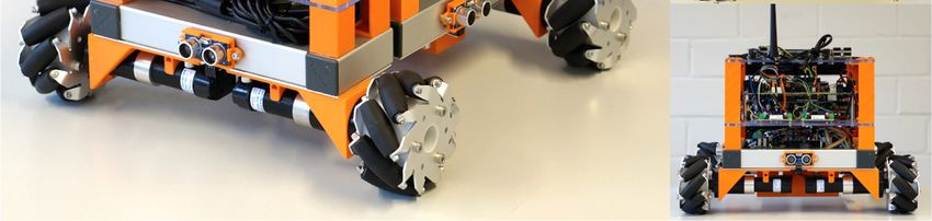
Computers 2019, 8, 25                                                                               2 of 16

grow historically [2]. First one SBC is used as a processing unit, and later other SBCs for different
sensors, actuators, or Human–Machine Interfaces (HMI) are added. Not focusing on the architecture
and planning to include new components for future projects lead to problems integrating those new
components. Comfort features, like visualization tools, could be mixed with actuators which must
fulfill hard real-time constraints in one operating system or framework, for example, in ROS (Robot
Operating System [3]). Thus, the architecture of those distributed systems within one robot becomes
much more important.
      This article describes a new concept for a modular system architecture for robotic systems, focusing
on distributed systems within a mobile robot. The article also includes an exemplary implementation
of the proposed architecture on a mobile robot, the DAEbot.
      This article is organized as follows: Section 2 presents the current state of the art focusing on
architectures used in robotics and the Operator–Controller Module (OCM). Section 3 describes the
conceptual model, including the architecture, communications, and how requirements on mobile
robots have been integrated. Section 4 shows the exemplary implementation of this conceptual model
with the DAEbot. Section 5 shows some results of this project. The last section summarizes the article
with a conclusion and outlook for upcoming projects.
      This article is an extended version of a previous article at the 24th International Conference on
Information and Software Technologies (ICIST 2018) [4]. The original conference paper has been
extended with a more detailed state of the art and the new central chapter “Conceptual Model”.

2. State of the Art

2.1. Single-Board Computers (SBCs) in Robotics
      The usage of SBCs is a step forward to developer-friendly robot designs. In contrast to
using industrial computers in robotics, SBCs are used in many areas, dedicated IDEs (integrated
development environments) are available, and communities can help within the development process.
Thus, developers do not necessarily need expert knowledge of the processing unit’s hardware and can
start with using available operating systems.
      Many design approaches (e.g., of mobile robots) use one single processing unit (e.g., SBC) to
control the complex technical system. A (single) Arduino Uno is used to run a surveillance robot for
outdoor security [5], a microcontroller controls an underwater robot [6], and a mini PC is used to
operate a hexapod robot for subsea operations [7].

2.2. Condition Monitoring
     The monitoring of the condition of a technical system can be used to detect anomalies and
off-nominal operating conditions [8]. To monitor the condition of hardware components, for example,
electrical motors help to detect problems earlier to prevent any hardware damage and to process a fault
diagnosis with the monitored data [9]. Strategies can be planned to react to failures (e.g., to trigger a
repair process [10]).

2.3. Architectures for Robotic Systems
     Robotic systems are often based on an ROS (Robot Operating System), which is widely accepted
as the standard framework for robotic system development [11]. ROS helps to develop a robot
easily by adding many ROS packages to a software stack, but developers are not led to focus on the
robot’s component structure or the underlying architecture. ROS can be implemented on various
operating systems (e.g., on real-time operating systems (RT-OS) or non-real-time operating systems).
This increases the chance to mix hard real-time and “soft” real-time using ROS packages with different
underlying operating systems. ROS itself is one example for a modular system, as different ROS
packages can be combined in a modular manner.
     The research on modular architectures is a well-established research topic (e.g., presented in [12]).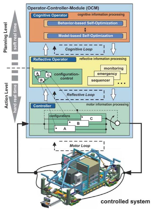
Computers 2019, 8, 25                                                                                 3 of 16

     In 1998, Mark W. Maier [2] published architecting principles for systems-of-systems.
His work defines systems-of-systems and describes architectural principles and the different layers
of communications.
     In [13], among other things, a design structure matrix is presented to analyze the modularity
and complexity of system-of-systems (SoS). It also describes different architectural designs, like a
centralized architecture, a distributed estimation architecture, and a distributed tasking architecture.
     The literature research also shows many architecture approaches for robotic systems. In [14],
a systematic mapping study on software architectures for robotic systems is described. The brief
comparison and quantification regarding a quality score were used to take a more in-depth look into
some of the presented architectures and extend the list with their own literature research results.
     Corke et al. [15] present DDX (Dynamic Data eXchange) as distributed software architecture for
robotic systems. This architecture divides the system into clients and computers. DDX provides two
programs to share data within the clients (store) and with other computers (catalog). In contrast to our
approach, DDX does not structure the architecture hierarchically.
     In [16], an architecture for distributed robotic systems is outlined, which divides the robot into a
client and server part. One disadvantage of this approach is that the server part of this architecture is
necessary and not optional to run features like state machine execution.
     Another software architecture was developed using the Orca [17] framework. The presented
architecture focuses on the abstraction layer of a user interface using a base station with a user interface,
a ground station, and two operators to interact with the ground vehicle. Lower abstractions, like the
internals of the used components, are not included in the ORCA framework.
     Yang et al. [18] outline a high-level software architecture. The robot’s software architecture is
distributed into a reactive layer, where sensing and acting with the environment is done on an adaptive
layer. The adaptive layer includes modeling, planning, and monitoring of a mobile robot. Both layers
are located on one computer, not on different processing units as a distributed system.
     For the SERA (Self-adaptive dEcentralized Robotic Architecture) approach [19],
related architectures have been reviewed. The SERA approach consists of a distributed system of
robots and a central station. SERA uses three layers on the robots, the component control layer,
change management layer, and the mission management layer, which are based on Kramer et al. [20].
In SERA, the three layers on the robot are located on one processing unit, not on different units
as a distributed system on the robot itself. A goal for the SERA is a decentralized architecture for
collaborative robots with the central station.

2.4. Operator–Controller Module (OCM)
     In 1979, Ropohl [21] introduced a hierarchical multilayer structure for a general system, which can
be a technical system (see Figure 1).
     The lowest layer, the so-called execution system, interacts directly with sensors and actuators,
the physical world of the technical system. The execution system itself interacts with the material,
the physical part of this Cyber-Physical System (CPS).
     The information system receives and transmits information from and towards the execution
system. This information is used for the processing of the sensor and actuator data from the
physical world.
     The top layer of this three-layer-approach is used for setting the target(s) of the activity system.
This layer is arranged hierarchically above the other two layers.
     The explicit distribution of one system into a hierarchically organized structure is also used with
the Operator–Controller Module (OCM).
     The OCM appeared in Naumann’s 2000 dissertation [22] as a concept for intelligent mechatronic
systems. Following Ropohl’s approach, the OCM decouples the controller for the direct interaction
with the physical system and its sensor and actuator signals from a reflective operator and a cognitive
operator (see Figure 2). In [23], the three layers are described in detail.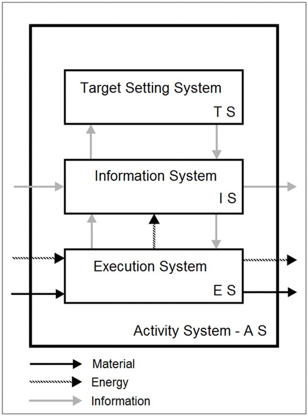
Computers 2019, 8, 25                                                                                                    4 of 16
Computers 2019, 8 FOR PEER REVIEW                                                                                              4

                         Figure 1. Ropohl’s Activity System [21] (Translated from German).
                         Figure 1. Ropohl’s Activity System [21] (Translated from German).
      The controller level stands for the motor loop with direct access to the technical system.
      The lowest layer,
The controller(s)            the so-called
                      are located              execution
                                      at the action     levelsystem,
                                                               where interacts     directly
                                                                        time-discrete         with sensors
                                                                                          constraints   need andto beactuators,
                                                                                                                       fulfilled.
the physical     world  of the  technical    system.    The  execution    system    itself
Interacting with the physical world leads to the need to guarantee compliance with hard    interacts  with   the  material,  the
                                                                                                                      real-time
physical partThe
constraints.      of this Cyber-Physical
                      controller    level canSystem
                                                 utilize (CPS).
                                                          many controllers, each having different configurations
      The    information    system
(e.g., emergency mode or standby).      receives   and transmits information from and towards the execution
system.
      TheThis    information
            reflective  operator is does
                                    used not
                                           for the
                                                haveprocessing
                                                      direct accessof the  sensor
                                                                       to the       and actuator
                                                                               technical   system. data   from the operator
                                                                                                    The reflective     physical
world.
is used to supervise the controllers in the reflective loop by processing the information from the
      The top This
controllers.     layerinformation
                        of this three-layer-approach          is used for setting
                                         is processed event-driven.                   the target(s)
                                                                             The reflective         of theneeds
                                                                                                operator      activity
                                                                                                                     tosystem.
                                                                                                                         decide
This  layer   is arranged   hierarchically      above    the other  two   layers.
which configurations of the controllers are used based on the robot’s environment and its task.
Also,Thethe explicit
            reflectivedistribution    of oneassystem
                        operator serves                  into a hierarchically
                                                 a middleware      between the organized        structure
                                                                                   controller and           is also used
                                                                                                     the cognitive         with
                                                                                                                       operator
the Operator–Controller        Module       (OCM).
and decouples hard real-time parts of the system from soft real-time parts.
      The OCM
      The          appeared
            cognitive   operatorin Naumann’s
                                     is the highest 2000   dissertation
                                                       level              [22] as a concept
                                                              in this architecture.            for intelligent
                                                                                        In a cognitive   loop, themechatronic
                                                                                                                     cognitive
systems.    Following     Ropohl’s     approach,     the  OCM     decouples     the  controller
operator is used to improve the behavior of the system on its planning level. This level         for  the  direct  interaction
                                                                                                                       includes
with   the physical   system   and
strategies for self-optimization.     its sensor   and   actuator  signals   from   a  reflective operator    and  a cognitive
operator
      The (see    Figure
            concept       2). In
                       of the  OCM[23],was
                                         the initially
                                              three layers    are described
                                                         developed              in detail.
                                                                       for self-optimizing      mechatronic systems [22].
The OCM was refined later and was used in several projects of the research cluster “Self-optimizing
systems in mechanical engineering (SFB614)” [24] (e.g., the RailCab project [25]). Metropolitan energy
systems [26] and ORC turbines [27] have also used the OCM design.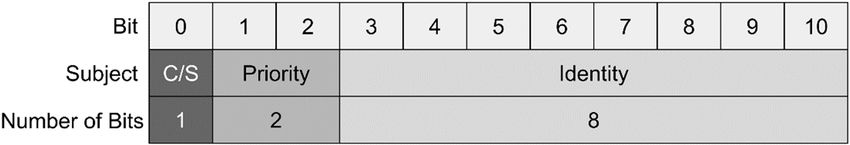
Computers 2019, 88,FOR
                   25 PEER REVIEW                                                                             5
                                                                                                        5 of 16

                    Figure 2. Architecture of the Operator–Controller Module (OCM) [23].
                    Figure 2. Architecture of the Operator–Controller Module (OCM) [23].
3. Conceptual Model
       The  controller level
       The conceptual   modelstands  for the motor
                               of a modular          loop
                                              software    with direct
                                                       architecture foraccess to therobotic
                                                                       distributed    technical system.
                                                                                            systems        The
                                                                                                      is based
controller(s)  are located
on the presented             at the
                      OCM. The       action level
                                  conceptual        where
                                                model      time-discrete
                                                       describes         constraintsadaption
                                                                  the implemented      need to of
                                                                                                be the
                                                                                                     fulfilled.
                                                                                                         OCM
Interacting   with  the physical  world  leads  to the need  to guarantee compliance
approach on the field of robotics to fulfill requirements on such a robotic system.     with  hard  real-time
constraints. The controller level can utilize many controllers, each having different configurations
(e.g., emergency mode or standby).
3.1. Architecture
       The reflective operator does not have direct access to the technical system. The reflective
       The proposed architecture consists of the three OCM layers: the controller(s), reflective operator,
operator is used to supervise the controllers in the reflective loop by processing the information from
and cognitive operator (see Figure 3). The controllers interact directly with actuators and sensors in
the controllers. This information is processed event-driven. The reflective operator needs to decide
a motor loop. The reflective operator processes the data from the controllers in an operating loop.
which configurations of the controllers are used based on the robot’s environment and its task. Also,
The reflective operator decides in which configuration the controllers are running and controls the
the reflective operator serves as a middleware between the controller and the cognitive operator and
robots to fulfill their given task(s) (e.g., to navigate through a room). The highest layer, the cognitive
decouples hard real-time parts of the system from soft real-time parts.
operator, runs an optimizing loop for the lower layers to optimize the behavior of the system
       The cognitive operator is the highest level in this architecture. In a cognitive loop, the cognitive
(e.g., to reduce power consumption). A Human–Machine Interface (HMI) can be implemented to both
operator is used to improve the behavior of the system on its planning level. This level includes
of the two operators, as an HMI is not required to fulfill hard real-time constraints. The architecture
strategies for self-optimization.
is divided into two parts: the local part, which can run the robot autonomously, and the cloud area,
       The concept of the OCM was initially developed for self-optimizing mechatronic systems [22].
to add additional computing power (e.g., to calculate complex (optimizing) software algorithms).
The OCM was refined later and was used in several projects of the research cluster “Self-optimizing
systems in mechanical engineering (SFB614)” [24] (e.g., the RailCab project [25]). Metropolitan energy
systems [26] and ORC turbines [27] have also used the OCM design.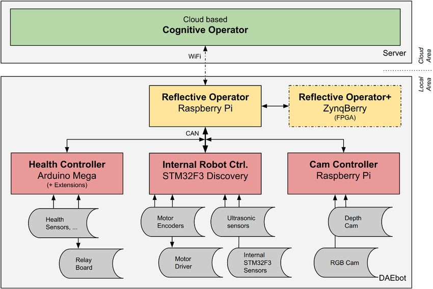
robots to fulfill their given task(s) (e.g., to navigate through a room). The highest layer, the cognitive
operator, runs an optimizing loop for the lower layers to optimize the behavior of the system (e.g., to
reduce power consumption). A Human–Machine Interface (HMI) can be implemented to both of the
two operators, as an HMI is not required to fulfill hard real-time constraints. The architecture is
Computers into
divided         8, 25 parts: the local part, which can run the robot autonomously, and the cloud area,
          2019, two                                                                                  6 ofto
                                                                                                          16

add additional computing power (e.g., to calculate complex (optimizing) software algorithms).

               Figure 3. Conceptual model for an architecture for a distributed robotic system.
               Figure 3. Conceptual model for an architecture for a distributed robotic system.
3.2. Autonomy vs. Cloud Computing
3.2. Autonomy vs Cloud Computing
      The article “Robots with their heads in the clouds” [28] argues that “cloud computing could make
robots smaller and smarter”. Modern mobile robots need to combine the ability to compute a high
amount of sensors, actuators, and software algorithms with the restriction of limited space for powerful
processing units and the needed battery packs to run those processing units. The proposed approach
divides the robotic system into two areas: one locally on the robot and one in the suggested cloud.
      The local area, consisting of the controllers and the reflective operator, is set up as an autonomous
client. Even without the connection to the cognitive operator, the robot needs to interact with its
environment and to fulfill its tasks. Unlike the original OCM approach, our architecture implements
the cognitive operator as a cloud service. The benefit of this distribution is that the local part can
be equipped with processing units which are low on energy but also do not have the computing
power to solve complex software algorithms (e.g., particle filters with a high amount of particles,
or neural network applications [29]). The cloud part allows adding this computing power while
not using the limited battery power of the mobile robot. A real-time connection to the cloud-based
cognitive operator is challenging [30] and not necessary, as the reflective operator defines the immediate
reaction of the robot. This ideally fits into the Internet of Things (IoT) domain and opens the path for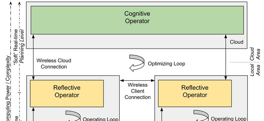
Computers 2019, 8, 25                                                                                7 of 16

seamless integration of technical systems into virtual environments, leading to real Cyber–Physical
Systems (CPS).

3.3. Time-Discrete vs Event-Driven
      One advantage of the OCM is the division into time-discrete and discrete logic (or event-driven)
behavior [31]. As in mechatronic systems, hard real-time constraints also need to be fulfilled in robotics.
The OCM divides the system into an action level (time-discrete with hard real-time constraints) and a
planning level (event-driven with soft real-time constraints).
      The controllers are mostly based on time-discrete constraints. That means that the data or
algorithms processed by the controllers need to be completed within a defined “hard” real time,
without exceptions. The controllers are directly interacting (action level) with the system’s sensors
and actuators and therefore need to guarantee compliance with hard real-time constraints. In case
of an emergency, the controller, for example, needs to stop the system’s motors without any delays
(e.g., fail-safe).
      The reflective operator can be implemented with lower real-time constraints (soft real-time).
Information processing depends on the data from the controllers and is, therefore, using event-driven
behavior such as event-triggered function calls. The reflective operator also implements the interface
to the planning level with the cloud-based cognitive operator. Comfort features, like visualization
tools or HMI interfaces, are only allowed to be used on the planning level. Processing those comfort
features could create latencies, which should never interrupt hard real-time processes.
      This isolation between both levels shall ensure that hard real-time tasks will never be harmed by
lower-prioritized tasks.

3.4. Communications
      The communications in the architecture are designed to serve the hard and soft real-time
conditions. On the action level (see Figure 3), the communication should be done in real-time, and on
the planning level (see Figure 3), a soft real-time connection is sufficient.
      Furthermore, the communication on the modular robot (local area) should be done in a bus
network topology and not with a point-to-point connection. This makes it easy to add new components
to the system, without changing the network topology [12]. Another advantage of a bus is that
watchdogs which are listening to the whole (local) robot agent’s communication for analysis or
error-detection features can be added. A widely used network bus in automotive and robot application
is the CAN-Bus. CAN has low hardware requirements and is also available in a real-time version [32].
      It is useful to keep the number of CAN frames low to increase the possibility of colliding CAN
frames (e.g., by adapting the publisher rate of a sensor depending on its need for the system).
      Figure 4 describes this adaptive publisher frequency with the example of ultrasonic sensors
attached on all four sides of a mobile robot. Data from the front ultrasonic sensor is essential if the
robot is driving forward. The front ultrasonic sensor will publish its data with 20 Hz. If the robot
stands still, all four sensors are running in a standby mode, publishing its data only with 1 Hz.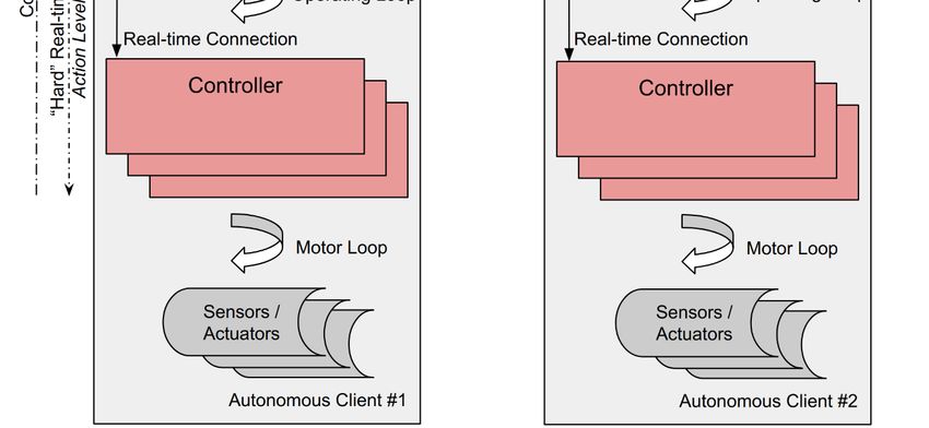
The cloud connection is typically a Machine-to-Machine (M2M) communication architecture
Computers
[30]. 2019, 8, 25 8 of 16
Figure 4. Adaptive publisher frequency (example: ultrasonic sensors).
Figure 4. Adaptive publisher frequency (example: ultrasonic sensors).
The cloud connection is typically a Machine-to-Machine (M2M) communication architecture [30].
3.5. Modularity
3.5. Modularity
In [12], the importance of the concept of modularity, especially in modern robotics, is described.
Robots [12],
In needtheto importance
adapt to future of thetasks
concept
or newof modularity,
environments especially
(e.g., byinconnection
modern robotics,
of a new is described.
sensor to
Robots
recognize need to adapt
objects) to beto future-proof.
future tasks or newnew
These environments
sensors can(e.g., by be
easily connection
included of in aour
new sensor to
architecture
recognize objects)
(e.g., by adding to be future-proof.
another controller to the These newThe
robot). sensors can easily
distribution be included
of the processing in units
our architecture
to different
(e.g., by adding
components another
within one controller
robot leadstointo the arobot).
modular Thedesign
distribution
approach.of theNewprocessing
components unitsonly
to different
need to
components
be included in within one robot
the system’s leads into a modular
communication design approach. New components only need to
bus system.
be included in the system’s communication bus system.
3.6. Computing Power and Complexity
3.6. Computing Power and Complexity
The complexity of a robot’s software and the high amount of sensor and actuators can easily be
adapted complexity
The to the OCM of a architecture
robot’s software usingandmultiple
the high processing
amount of sensor units and actuators
within one robotcan easily be
for the
adapted to the OCM architecture using multiple processing units within
controller(s) and the reflective operator. One advantage of single-board computers (SBCs) or one robot for the controller(s)
and the reflectivein
microcontrollers operator. One advantage
mobile robots is the deviceof single-board
size and energy computers
efficiency.(SBCs)
Withorthemicrocontrollers
usage of multiple in
mobile robots is the device size and energy efficiency. With the usage
processing units in a single robot, the computing power can be adapted to the needed complexity of multiple processing units in
a(e.g.,
single robot,another
adding the computing
controller power can bewith
to interact adapted to the needed
new hardware complexity
sensors (e.g., adding another
or actuators).
controller to interact with new hardware sensors or actuators).
Mostly, the complexity increases from the bottom of the three-layer architecture to the top (see
FigureMostly,
3). Onthethe complexity
lowest level,increases from preprocess
the controllers the bottomsensors
of the andthree-layer
actuatorsarchitecture
in control loops.to the top
Those
(see Figure tasks
processing 3). On arethe lowest
simple andlevel,
mustthe controllers
fulfill preprocess
hard real-time sensors and
constraints. On theactuators
next layerin control
of the
loops. Those processing tasks are simple and must fulfill hard real-time
processing hierarchy, the reflective operator runs more complex software algorithms (e.g., mapping constraints. On the next
layer of the processing hierarchy, the reflective operator runs more complex
or computer vision algorithms). Very complex or data-intensive algorithms are running on the cloud- software algorithms
(e.g.,
basedmapping
cognitive or operator.
computerThis vision algorithms).
allows computer Very complex
power to beoradded
data-intensive algorithms
to or removed fromare therunning
mobile
on the cloud-based cognitive operator. This allows computer power to
robot as it is needed. The cloud-based algorithms can also be used when the robot is disconnected be added to or removed from
the mobile
(e.g., robot different
to simulate as it is needed.
optimizing Theand
cloud-based algorithms can also be used when the robot is
learning strategies).
disconnected (e.g., to simulate different optimizing
Also, the modular approach makes it possible to add and learning strategies).
the most suitable hardware for tasks. For
Also, the modular approach makes it possible
example, an FPGA board can be added to the robot to run computer to add the mostvision
suitable hardware
algorithms for tasks.
much more
For example,
efficiently an ARM-based
than FPGA boardprocessing
can be added to the robot to run computer vision algorithms much more
units.
efficiently than ARM-based processing units.
3.7.
3.7. Safety
Safety and
and Redundancy
Redundancy
The dependency on a single processing unit is one disadvantage of such single-processing unit
systems. If the only processing unit fails, the system itself will fail. With complex networks, a technical
system’s robustness can be increased (e.g., by adding redundancies [33]). Using a distributed system
in one robot has the advantage of having such a network of many processing units onboard which can
bring the system into a save state or even take over tasks of the failing processing unit.Computers 2019, 8, 25 9 of 16
It is recommended to implement watchdogs to check the conditions of the robot to detect failures
of the system. This can either be done by adding another SBC, as a watchdog listening to the
communication bus, or each SBC can run global and local watchdogs. A local watchdog can be
used to prevent misbehavior of a single component (e.g., running the robot’s wheels even if the
same component detects an obstacle). Global watchdogs can be used to detect communication loss
(e.g., running the robot’s wheels even if the connection to the reflective operator is lost).
The modular design approach also supports the use of backup or redundant components. Backup
components can be added to the system to take over tasks if a component is struggling.
3.8. Adaptive Component and Sensor Usage
Another challenge for mobile robots is to be as energy-efficient as possible. The proposed
approach uses mostly energy-efficient SBCs or microcontrollers, but due to the number of components,
the overall energy consumption is high. To prevent this, the robot should be able to shut down or start
components and sensors as they are needed. If, for example, the usage of a camera is unnecessary,
the component can be switched off completely. It should also be possible to turn sensors and actuators
with high energy consumption off and on.
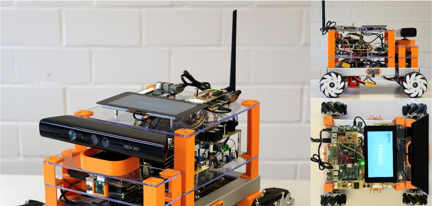
4. Design of the DAEbot
The DAEbot (Distributed Architecture Evaluation Robot) has been developed to evaluate
distributed architectures within one robot, in this case, the presented conceptual model based on
the OCM. The DAEbot (see Figure 5) consists of a modular structure, which can be extended with
actuators and sensors for different applications (e.g., with a depth camera to navigate autonomously
to a given2019,
Computers location). TheREVIEW
8 FOR PEER cognitive operator for the DAEbot is under development. 10
Figure5.5. DAEbot
Figure DAEbot as
asaademonstrator
demonstratorfor
forthe
theoperator–controller-based
operator–controller-baseddistributed
distributedsystem.
system.
4.1. Communication
The primary communication in the DAEbot is done via Controller Area Network (CAN) in a
publisher–subscriber concept. The de facto standard in robotics ROS
(https://wiki.ros.org/ROS/Concepts) is also based on this publisher–subscriber concept. A publisher
(e.g., an ultrasonic sensor) offers its data to the system. A subscriber (e.g., a processing algorithm) canComputers 2019, 8, 25 10 of 16
All microcontrollers of the DAEbot are SBCs. The robot basis is a self-designed platform which
is driven by four mecanum wheels [34]. The robot basis contains motor encoders, motor drivers,
Figure 5.
and ultrasonic DAEbot as
sensors. a demonstrator
This for the operator–controller-based
chapter describes all components of the distributed
DAEbot, system.
including the
implemented communication framework and safety and redundancy functionalities.
4.1. Communication
4.1. Communication
The primary communication in the DAEbot is done via Controller Area Network (CAN) in a
The primary communication
publisher–subscriber concept. in the TheDAEbot de is donefactovia Controller
standard Area in Network
robotics(CAN)ROS in a
publisher–subscriber concept. The de
(https://wiki.ros.org/ROS/Concepts) factobased
is also standard in publisher–subscriber
on this robotics ROS (https://wiki.ros.org/ROS/
concept. A publisher
Concepts)
(e.g., is also based
an ultrasonic sensor) onoffers
this publisher–subscriber
its data to the system. concept. A publisher
A subscriber (e.g., a (e.g., an ultrasonic
processing algorithm) sensor)
can
offers its data
subscribe to this to sensor
the system. A subscriber
data for its purpose. (e.g., a processing algorithm) can subscribe to this sensor
data For
for its
thispurpose.
concept, a self-developed CAN ID framework has been implemented (see Figure 6),
which For this concept,
allows changingathe self-developed CAN ID
priority of messages framework Therefore,
dynamically. has been implemented
the common CAN (see Figure 6),
identifier
which
(11 bits)allows changing
is altered the priority
into three of messages
parts: the C/S bit, two dynamically. Therefore,
priority bits, the common
and an eight-bit CAN identifier
identifier. The first
(11 bits) is altered
bit defines into threeCAN
if the attached parts:frame
the C/S bit, two
contains priority
sensor databits,
fromanda an eight-bit(C/S
controller identifier.
= 1) orThe first bit
command
defines
data if the
from theattached
operator CAN(C/Sframe
= 0). contains
With thesensor next data
two from a controller
bits, the priority (C/S
of the = 1) or command
CAN frame candata be
from the operator
configured as urgent (C/S = 0).
(00), With
high (01),the next two
medium bits,
(10), orthe
lowpriority
(11). Asofthese
the CAN frame
priorities can
can bebe configured
reconfigured
as urgent
for (00), highcritical
each message, (01), medium
messages(10), canorbelow (11). As (e.g.,
prioritized these the
priorities
prioritycanof be
thereconfigured
message to stopfor each
the
message,
robot’s criticalcan
wheels messages
be set to can be prioritized
urgent (e.g., thestop
if an emergency priority
needsof the
to bemessage to stopLow
performed). the robot’s wheels
identifiers are
can be set toover
prioritized urgent if anones
higher emergency
in CANstop on needs to be performed).
the hardware site, meaningLow that
identifiers
command are prioritized
data is alwaysover
higher ones
handled prior in to
CANsensoron the hardware
data, following site,
itsmeaning
personal that command
priority. data
The last is always
eight handled
bits contain prior to
a personal
sensor data,
identity for eachfollowing
actuator itsand
personal
sensorpriority.
value of theThesystem.
last eight
As bits contain
a result, a CANa personal
frame can identity for each
be transmitted
actuator
to the same and sensor
entity eithervalue of the to
to switch system. As amode
a different result,bya changing
CAN frame the can
C/S be
bit transmitted
or to transmit tothe
thesensor
same
entity either to switch to a different mode by changing the C/S bit or to transmit the sensor data.
data.
Figure 6. CAN communications ID for the DAEbot.
The DAEbot communications framework uses three modes. Mode “0” is used to switch off a
publisher (e.g., if the sensor data is not needed for the current task of the robot). With a mode “1”
message, a publisher can be (re)configured by attributing the sensor sample time. With a mode “2”
message, the operator asks the controller for one-time data transmission.
The publisher–subscriber implementation of the DAEbot can be configured to the exact needs
of the robot’s application in order to use the controller’s hardware resources efficiently. The use
of the priority bits in the CAN ID also helps to prioritize critical over less-important information
(e.g., to prefer real-time controller messages over non-time-critical command messages).
In addition to the local CAN communication, the DAEbot is connected via WiFi to the cloud-based
cognitive operator.
4.2. Modular Design
The DAEbot is based on SBCs which are connected via CAN. This modular approach makes the
DAEbot future-proof (e.g., by upgrading the used SBC with new ones). More SBCs can be added to the
system for future tasks (e.g., to add more efficient or more powerful processing units to the system).
4.3. Components
The DAEbot utilizes five SBCs as operator or controller units implementing the OCM approach.
The three controllers (see Figure 7, red bottom layer) are directly connected with several actuatorsThe DAEbot is based on SBCs which are connected via CAN. This modular approach makes the
DAEbot future-proof (e.g., by upgrading the used SBC with new ones). More SBCs can be added to
the system for future tasks (e.g., to add more efficient or more powerful processing units to the
system).
Computers 2019, 8, 25
4.3. Components 11 of 16
The DAEbot utilizes five SBCs as operator or controller units implementing the OCM approach.
The three controllers
and sensors (grey). The(see Figure 7,
reflective red bottom
operator andlayer) are directly
the reflective connected(yellow
operator+ with several
middle actuators
layer) are
and sensors
interacting with(grey). The reflective
the controllers operator
via CAN. and
The the reflective
cognitive operator+
operator (yellow
(green middle
top layer) layer)
will are to
be used
interacting with the controllers
optimize the distributed system. via CAN. The cognitive operator (green top layer) will be used to
optimize the distributed system.
Figure7.7.Components
Figure ofthe
Components of theDAEbot.
DAEbot.
TheThe
mechanical design of the DAEbot itself is designed with spatial layers for the controllers and
mechanical design of the DAEbot itself is designed with spatial layers for the controllers
a layer for the local operators (see Figure
and a layer for the local operators (see1)Figure
to demonstrate the software
1) to demonstrate architecture.
the software As theAs
architecture. presented
the
architecture is modular, more components can easily extend the system for future tasks. Different
SBC/microcontrollers are used to evaluate those popular processing unit families and to demonstrate
the suitability of them in such a mobile robot. The DAEbot combines multicore SBCs (Raspberry Pi
(https://www.raspberrypi.org/products/)), an Arduino Mega (https://store.arduino.cc/arduino-
mega-2560-rev3) with lots of GPIOs, an STM32F3Discovery (https://www.st.com/en/evaluation-
tools/stm32f3discovery.html), and an FPGA board (ZynqBerry TE0726-03M (https://shop.trenz-
electronic.de/en/TE0726-03M-ZynqBerry-Zynq-7010-in-Raspberry-Pi-form-factor)). A (Raspberry Pi)
touch display is used for visualization features.
4.3.1. Internal Robot Controller
The Internal Robot Controller (IRC) connects and processes the actuators and sensors which
are necessary for the movement of the robot. The STM32F3Discovery has been extended with a
self-developed board to add a CAN interface, pinouts, and additional ports and interfaces to connect
the periphery. The IRC runs the motor drivers and receives rotation data from the motor encoders.
It also connects four ultrasonic sensors and processes a magnetometer and a gyroscope.
The microcontroller uses the operating system FreeRTOS [35] to satisfy the real-time requirements.
The IRC implements safety features like interrupting the motors if the ultrasonic sensors recognize an
obstacle movement direction.
4.3.2. Cam Controller
The Cam(era) Controller (CC) extends the DAEbot with image sensors, which are used for
an autonomous navigation application to demonstrate the robot’s capabilities. First, a RaspberryComputers 2019, 8, 25 12 of 16
Pi RGB camera is connected to the Raspberry-Pi-based CC. Secondly, a Microsoft Kinect
(https://developer.microsoft.com/en-us/windows/kinect) depth camera is set up. Both cameras
use OpenCV (https://opencv.org/) to recognize objects or obstacles. The Raspberry Pi RGB camera
has the advantage of low power consumption compared to the Kinect. The Kinect outperforms the RGB
camera in a low-light environment or darkness. The Kinect is also used to get depth data from objects.
The operator’s task is to decide which camera is best for the current situation and task (e.g., in case of
darkness, the depth camera would be the obvious choice over the RGB camera). The other camera can
be disabled or, in the case of the Kinect, be switched off entirely with a relay. A CAN shield is used to
include the CC into the local DAEbot network. A custom Linux-based RTOS has been built with the
Yocto project (https://www.yoctoproject.org/).
4.3.3. Health Controller
The Health Controller (HC) is used to collect the condition data of the robotic system. It provides
different types of information about the system. This information can be used by the operator(s)
to (re)configure the system behavior (e.g., in case of critical battery or abnormally high motor
temperatures).
First, the HC collects information about the energy of the systems. For this, the current power
consumption of the system, the current voltage, and the remaining capacity of the battery are captured.
Second, the temperature of the battery, the motor drivers, and the motors are monitored with external
temperature sensors. Third, the HC captures environment information, like environment temperature,
air pressure, and humidity. Those external sensors are set up on a self-developed extension board for
an Arduino Mega. The data of the HC is transmitted to the reflective operator. The reflective operator
calculates the current condition of the system (the health) out of this data. If, for example, the battery
is nearly empty but the current power consumption is high, the health of the system is in a critical
condition. High temperatures on the motor drivers could either mean that the cooling of the system is
not appropriate, or the motors are running too fast.
Also, as the HC has enough spare GPIOs, it connects a self-developed relay board with 10 relays
which are used to switch components off or on. With the HC, it is possible to switch off the Kinect or
any SBC of the system to reduce the power consumption.
A scheduler was developed to manage the flow of the multiple publishers, as Arduino’s are
usually not equipped with an OS.
4.3.4. Reflective Operator
The reflective operator of the DAEbot is located on another Raspberry Pi extended with a touch
display to visualize and configure the robot and a CAN shield for its communication. The main
task of the operator is to handle the information from the three underlying controllers. Therefore,
state machines are developed with MATLAB Simulink (Stateflow) or Yakindu SCT. These state
machines react to incoming CAN frames by executing predefined work sequences (e.g., stopping the
motor if an obstacle is detected). It also generates the health status of the DAEbot by combining all of
the data from the HC with the information from other modules of the distributed system, like data from
the Internal Robot Controller. The current status of the robot is not healthy if, for example, the motors
of the robot are not running but the temperature of the motor drivers is too high. The reflective operator
defines in which mode the robot and all of its components are used. For example, if the battery is nearly
empty, the robot switches to a power-saving mode to reduce energy consumption. This is done by
setting the maximum velocity to a lower limit and by turning off the reflective operator+. The reflective
operator is also used to process tasks like following an object. First, the reflective operator gets this task
(e.g., with a display command executed by a human). Second, the reflective operator sets up the robots
to fulfill this task. In this case, the motor driver and the CC need to be started. Third, the reflective
operator processes the information from the CC (e.g., the distance to an object) and transmits new
velocity values to the IRC.Computers 2019, 8, 25 13 of 16
The system’s logic was designed model-based with state diagrams in several modules like
battery management or motor logic. Independent services are designed to use the parallel computing
capabilities of the multicore Raspberry Pi.
The reflective operator also (re)configures the controllers’ publishers by setting up the publishers
dynamically to other sample rates or priorities due to the current tasks and requirements.
Also, the operator can visualize data on the attached display. In particular, the data from the HC,
like temperatures or environment information, can be monitored. The touch display is also used to
change modes of the robot. It could, for example, be set to an energy-saving mode where the CC is
entirely switched off.
4.3.5. Reflective Operator+
The goal of the reflective operator+ is to demonstrate the possibility to add computing resources
to the operator whenever it is needed. The ZynqBerry TE0726-03M SBC has the form factor of a
Raspberry Pi but uses a heterogeneous chip architecture consisting of a small FPGA SoC and an
ARM-Cortex-A9-based co-microprocessor. Hence, the Operator+ can take over tasks from the reflective
operator or even run massively parallel tasks (e.g., for computer vision tasks [36]) for which an
FPGA is more suitable than the ARM-based Raspberry Pi. One parallel task which the reflective
operator+ processes are OpenCV algorithms to detect obstacles in the video stream from the cameras.
The reflective operator+ can be switched off with a relay when it is not used.
4.3.6. Cognitive Operator
The cognitive operator will run self-optimizing and planning algorithms as cloud services. It will
extend the distributed system on the DAEbot with a remote cloud area. The cognitive operator
will be connected via WiFi or mobile communications. Complex algorithms can be assigned to the
cognitive operator, and all data from the robot will be saved in a database to run long-term analyses of
the DAEbot.
4.4. Safety and Redundancy
Each component of the DAEbot runs a local software watchdog to check if the connection to other
components is working. The component reacts with a predefined strategy if the connection breaks
down. For example, a loose connection of the IRC to the operators leads to stopping the motors of the
mobile robot to prevent possible damage.
Self-healing behavior can be processed with the HC (e.g., by restarting the operator(s) if any
dysfunction of it is detected). The operator then runs self-checking algorithms to solve its dysfunction
(e.g., a CAN connection malfunction).
In other critical conditions, like high motor driver temperatures or a low battery, the HC transmits
warnings to the reflective operator. These warnings are also visualized on the robot’s display.
5. Results
The Operator–Controller Module (OCM) has successfully been adapted to robotics. The main
result, the experiment to bring the conceptual model to a real-world robot, was successful. With the
DAEbot, a distributed system within one robot has been developed. In contrast to systems with a
single processing unit, architectures with a modular and distributed concept help to decouple their
tasks and features on different levels. The conceptual model uses hard real-time constraints within
the described controllers (e.g., to run the motors) and adds non-time-critical visualization on the
operator layers. The usage of a distributed system also helps to integrate, for example, safety features
or redundancies to a robot.
Some safety features, like terminating a communication channel, could successfully be tested with
the DAEbot. With the implemented watchdog, the DAEbot automatically recognizes a communication
loss (e.g., of the IRC), stops the robot immediately, and transmits a notification to the entire system.Computers 2019, 8, 25 14 of 16
The implemented communication framework fits into the architecture’s main design
characteristics with its ability to change the controller’s publishing rate by the reflective operator.
The described example, the adaptive publisher frequency (see Figure 4), allows the IRC to process
sensor information only as fast as it is needed, which relieves the CPU usage. If, for example, the robot
drives forward, the data from the ultrasonic sensor facing the back of the robot is not necessary.
With the ability to set this publisher rate, the amount of frames on the network decreases, and with it,
the possibility to have colliding CAN frames.
With its HC, the DAEbot can monitor the system and environment conditions. This condition
information can be analyzed and used to adapt the distributed system to the robot’s tasks in future
projects. With the ability to monitor the system’s energy consumption with the HC, strategies to save
energy can be developed. The distributed system also allows saving energy by switching off sensors
or processing units if they are not used. The DAEbot, for example, can activate a depth sensor with a
relay if the results of the RGB cam are not sufficient.
The modular approach is necessary to provide the computing power using SBCs or small
microcontrollers as processing units even for complex software algorithms. In the case of the DAEbot,
widely used SBCs, like Arduino Mega, STM32 boards, or the Raspberry Pi, have been used. All of those
SBCs fulfilled their tasks sufficiently. An FPGA board has been integrated to run massively parallel
algorithms, like computer vision tasks. Bringing a robotic system into the cloud via the cognitive
operator gives nearly unlimited resources to optimize the system.
The development process of the DAEbot was helpful to evaluate and refine the concept for the
modular software architecture.
6. Conclusions
This article presents the concept of a modular system architecture for distributed robotic systems.
This concept is based on the Operator–Controller Module (OCM) which was adapted for the usage of
mobile robots. The article also outlines suggestions on communication or safety and redundancy.
With the evaluated design of the DAEbot, the presented architecture has successfully been applied.
The DAEbot development outlines some aspects of its technical implementation. The experiment
also shows that the decentralized approach in robots is useful, for example, to design scalable robot
platforms which can easily be extended with other components.
In a future project, the DAEbot will be extended with an analysis tool for condition monitoring
and fault-tolerance strategies. This analysis tool will monitor the current state of the robot with the
reflective operator and long-term analysis of its conditions in the cloud. Therefore, the cognitive
operator will be implemented with planning and self-optimizing algorithms. Cloud computing
principles, especially for robotics [30,37] (e.g., neural network applications [29]), will be evaluated with
the DAEbot. The DAEbot will also be used in a multirobot network [38] (e.g., alongside the AMiRo
(Autonomous Mini Robot) [1]) to test the multilayer robot cooperation capabilities of the presented
architecture. These future experiments will refine the proposed modular architecture for distributed
robotic systems.
Author Contributions: Writing—original draft, U.J.; Writing—review & editing, C.W. and P.S.
Funding: This research received no external funding.
Conflicts of Interest: The authors declare no conflict of interest.
References
1. Herbrechtsmeier, S.; Korthals, T.; Schöpping, T.; Rückert, U. AMiRo: A Modular & Customizable
Open-Source Mini Robot Platform. In Proceedings of the 2016 20th International Conference on System
Theory, Control and Computing (ICSTCC), Sinaia, Romania, 13–15 October 2016. [CrossRef]
2. Maier, M.W. Architecting principles for systems-of-systems. Syst. Eng. J. Int. Counc. Syst. Eng. 1998, 1,
267–284. [CrossRef]Computers 2019, 8, 25 15 of 16
3. Quigley, M.; Conley, K.; Gerkey, B.P.; Faust, J.; Foote, T.; Leibs, J.; Wheeler, R.; Ng, A.Y. ROS: An open-source
Robot Operating System. In Proceedings of the ICRA Workshop on Open Source Software, Kobe, Japan,
12–17 May 2009.
4. Jahn, U.; Wolff, C.; Schulz, P. Design of an Operator-Controller Based Distributed Robotic System.
In Communications in Computer and Information Science, Proceedings of the International Conference on Information
and Software Technologies 2018, Vilnius, Lithuania, 4–6 October 2018; Springer: Cham, Switzerland, 2018;
Volume 920, pp. 59–70. [CrossRef]
5. Meghana, S.; Nikhil, T.V.; Murali, R.; Sanjana, S.; Vidhya, R.; Mohammed, K.J. Design and implementation
of surveillance robot for outdoor security. In Proceedings of the RTEICT 2017 2nd IEEE International
Conference on Recent Trends in Electronics, Information and Communication Technology, Proceedings 2018,
Bangalore, India, 19–20 May 2017; pp. 1679–1682. [CrossRef]
6. Tang, Z.; Feng, H. Design of an ocean current roaming underwater robot. In Proceedings of the 2017 4th
International Conference on Systems and Informatics, ICSAI 2017, Hangzhou, China, 11–13 November 2017;
pp. 229–233. [CrossRef]
7. Davliakos, I.; Roditis, I.; Lika, K.; Breki, C.M.; Papadopoulos, E. Design, development, and control of a tough
electrohydraulic hexapod robot for subsea operations. Adv. Robot. 2018, 32, 477–499. [CrossRef]
8. Bunch, L.; Breedy, M.; Bradshaw, J.M.; Carvalho, M.; Suri, N.; Uszok, A.; Hansen, J.; Pechoucek, M.; Marik, V.
Software Agents for Process Monitoring and Notification. In Proceedings of the 2004 ACM Symposium
on Applied Computing, SAC ’04, Nicosia, Cyprus, 14–17 March 2004; ACM: New York, NY, USA, 2004;
pp. 94–100. [CrossRef]
9. Nandi, S.; Toliyat, H.A.; Li, X. Condition Monitoring and Fault Diagnosis of Electrical Motors—A Review.
IEEE Trans. Energy Convers. 2005, 20, 719–729. [CrossRef]
10. Xi, W.; Feng, Y.; Zhou, Y.; Xu, B. Condition monitoring and plenary diagnostics strategy based on event
driven threads. In Proceedings of the 2008 International Conference on Condition Monitoring and Diagnosis,
CMD 2008, Beijing, China, 21–24 April 2008; pp. 576–578. [CrossRef]
11. Javier, F.; Lera, R.; Balsa, J.; Casado, F.; Fernández, C.; Rico, F.M.; Matellán, V. Cybersecurity in Autonomous
Systems: Evaluating the performance of hardening ROS. In Proceedings of the Waf2016, Málaga, Spain,
16–17 June 2016.
12. Schöpping, T.; Korthals, T.; Hesse, M.; Ulrich, R. Generic Architecture for Modular Real-time Systems in
Robotics. In Proceedings of the ICINCO 2018 15th International Conference on Informatics in Control,
Automation and Robotics, Porto, Portugal, 29–31 July 2018. [CrossRef]
13. Raz, A.K.; DeLaurentis, D.A. System-of-Systems Architecture Metrics for Information Fusion: A Network
Theoretic Formulation. In Proceedings of the AIAA Information Systems-AIAA Infotech @ Aerospace,
AIAA SciTech Forum, Grapevine, TX, USA, 9–13 January 2017; pp. 1–14. [CrossRef]
14. Ahmad, A.; Babar, M.A. Software architectures for robotic systems: A systematic mapping study. J. Syst. Softw.
2016, 122, 16–39. [CrossRef]
15. Corke, P.; Sikka, P.; Roberts, J.; Duff, E.; Centre, C.I.C.T. DDX: A Distributed Software Architecture for
Robotic Systems. In Proceedings of the Australasian Conference on Robotics and Automation (ACRA 2004),
Brisbane, Australia, 6–8 December 2004.
16. Tikanmäki, A.; Röning, J. Property service architecture for distributed robotic and sensor systems.
In Proceedings of the International Conference on Informatics in Control, Automation and Robotics 2007,
Angers, France, 9–12 May 2007; pp. 1–7.
17. Kaupp, T.; Brooks, A.; Upcroft, B.; Makarenko, A. Building a software architecture for a human-robot team
using the orca framework. In Proceedings of the 2007 IEEE International Conference on Robotics and
Automation, Roma, Italy, 10–14 April 2007; pp. 3736–3741. [CrossRef]
18. Yang, S.; Mao, X.; Yang, S.; Liu, Z. Towards a hybrid software architecture and multi-agent approach for
autonomous robot software. Int. J. Adv. Robot. Syst. 2017, 14, 1–15. [CrossRef]
19. Garcia, S.; Menghi, C.; Pelliccione, P.; Berger, T.; Wohlrab, R. An Architecture for Decentralized, Collaborative,
and Autonomous Robots. In Proceedings of the 2018 IEEE 15th International Conference on Software
Architecture, ICSA 2018, Seattle, WA, USA, 30 April–4 May 2018; pp. 75–84. [CrossRef]
20. Kramer, J.; Magee, J. Self-managed systems: An architectural challenge. In Proceedings of the FoSE 2007:
Future of Software Engineering 2007, Minneapolis, MN, USA, 23–25 May 2007; pp. 259–268. [CrossRef]Computers 2019, 8, 25 16 of 16
21. Ropohl, G. Allgemeine Technologie: Systemtheorie der Technik, 3. auflage ed.; Universitätsverlag Karlsruhe:
Karlsruhe, Germany, 2009; p. 360. [CrossRef]
22. Naumann, R. Modellierung und Verarbeitung Vernetzter Intelligenter Mechatronischer Systeme, fortschritt-berichte
vdi, reihe 20, nr. 318 ed.; VDI-Verl.: Düsseldorf, Germany, 2000; p. 180.
23. Gausemeier, J.; Kahl, S. Architecture and Design Methodology of Self-Optimizing Mechatronic Systems.
In Mechatronic Systems Simulation Modeling and Control; InTech: London, UK, 2010; pp. 255–271.
24. Adelt, P.; Donoth, J.; Gausemeier, J.; Geisler, J.; Henkler, S.; Kahl, S.; Klöpper, B.; Krupp, A.; Münch, E.;
Oberthür, S.; et al. Selbstoptimierende Systeme des Maschinenbaus: Definitionen, Anwendungen, Konzepte
(HNI-Verlagsschriftenreihe); Universität Paderborn Heinz Nixdorf Institut: Paderborn, Germany, 2009.
25. Gausemeier, J.; Steffen, D.; Donoth, J.; Kahl, S. Conceptual Design of Modularized Advanced Mechatronic
Systems. In Proceedings of the International Conference on Engineering Design (ICED09) 2009, Palo Alto,
CA, USA, 24–27 August 2009; pp. 263–274.
26. Wolff, C.; Lippmann, T.; Lauschner, U. Systems engineering for metropolitan energy systems-Ruhrvalley.
In Proceedings of the 2017 IEEE 9th International Conference on Intelligent Data Acquisition and Advanced
Computing Systems: Technology and Applications, IDAACS 2017, Bucharest, Romania, 21–23 September
2017; Volume 1, pp. 425–430. [CrossRef]
27. Wolff, C.; Knirr, M.; Priebe, K.P.; Schulz, P.; Strumberg, J. A layered software architecture for a flexible and
smart organic rankine cycle (ORC) turbine—Solutions and case study. Inf. Technol. Control 2018, 47, 349–362.
[CrossRef]
28. Guizzo, E. Robots with their heads in the clouds. IEEE Spectr. 2011, 48, 17–18. [CrossRef]
29. Da Silva, I.J.; Vilao, C.O.; Costa, A.H.; Bianchi, R.A. Towards robotic cognition using deep neural network
applied in a goalkeeper robot. In Proceedings of the 2017 LARS 14th Latin American Robotics Symposium
and 2017 5th SBR Brazilian Symposium on Robotics, LARS-SBR 2017—Part of the Robotics Conference 2017
2017, Curitiba, Brazil, 8–11 November 2017; pp. 1–6. [CrossRef]
30. Wan, J.; Tang, S.; Yan, H.; Li, D.; Wang, S.; Vasilakos, A.V. Cloud robotics: Current status and open issues.
IEEE Access 2016, 4, 2797–2807. [CrossRef]
31. Oberschelp, O.; Hestermeyer, T.; Kleinjohann, B.; Kleinjohann, L. Design of Self-Optimizing Agent-Based
Controllers. In Proceedings of the CfP Workshop 2002—Agent-Based Simulation 3, Chair of Operations
Research and System Theory University of Passau, Passau, Germany, 7–9 April 2002.
32. Migliavacca, M.; Bonarini, A.; Matteucci, M. RTCAN: A real-time CAN-bus protocol for robotic applications.
In Proceedings of the ICINCO 2013 10th International Conference on Informatics in Control, Automation
and Robotics, Reykjavik, Iceland, 29–31 July 2013; Volume 2.
33. Shang, Y.L. Local natural connectivity in complex networks. Chin. Phys. Lett. 2011, 28, 22–26. [CrossRef]
34. Rohrig, C.; Hess, D.; Kunemund, F. Motion controller design for a mecanum wheeled mobile manipulator.
In Proceedings of the 1st Annual IEEE Conference on Control Technology and Applications, CCTA 2017,
Mauna Lani, HI, USA, 27–30 August 2017; pp. 444–449. [CrossRef]
35. Barry, R. Mastering the FreeRTOS TM Real Time Kernel, A Hands-On Tutorial Guide 2016; Real Time Engineers
Ltd.: Glasgow, Scotland, 2016; p. 398.
36. Honegger, D.; Oleynikova, H.; Pollefeys, M. Real-time and low latency embedded computer vision hardware
based on a combination of FPGA and mobile CPU. In Proceedings of the IEEE International Conference on
Intelligent Robots and Systems 2014, Chicago, IL, USA, 14–18 September 2014; pp. 4930–4935. [CrossRef]
37. Hu, G.; Tay, W.P.; Wen, Y. Cloud Robotics: Architecture, Challenges and Applications. IEEE Netw. 2012, 26,
21–28. [CrossRef]
38. Iocchi, L.; Nardi, D.; Salerno, M. Reactivity and Deliberation: A Survey on Multi-Robot Systems. In Balancing
Reactivity and Social Deliberation in Multi-Agent Systems, From RoboCup to Real-World Applications (Selected
Papers from the ECAI 2000 Workshop and Additional Contributions); Springer: Berlin/Heidelberg, Germany,
2001; pp. 9–32. [CrossRef]
© 2019 by the authors. Licensee MDPI, Basel, Switzerland. This article is an open access
article distributed under the terms and conditions of the Creative Commons Attribution
(CC BY) license (http://creativecommons.org/licenses/by/4.0/).You can also read