Affinity User's Guide - Document No. MAN-AFT-0001 - Guralp Systems
←
→
Page content transcription
If your browser does not render page correctly, please read the page content below

Affinity

User's Guide
Document No. MAN-AFT-0001

Issue F - June, 2019

 Designed and manufactured by
 Güralp Systems Limited
 3 Midas House, Calleva Park
 Aldermaston RG7 8EA
 England
Affinity                                                                                                                 Contents

Table of Contents

1 Preliminary Notes...........................................................................................................5
   1.1     Proprietary Notice......................................................................................................5
   1.2     Cautions and Notes...................................................................................................5
   1.3     Manuals and Software...............................................................................................5
   1.4     Conventions...............................................................................................................5

2 Introduction.....................................................................................................................6
   2.1 Applications...............................................................................................................6
   2.2 Key features...............................................................................................................7

3 The Affinity documentation...........................................................................................8

4 Getting Started................................................................................................................9
   4.1 Introduction................................................................................................................9
   4.2 Connecting to the network port.................................................................................9
      4.2.1 DHCP-assigned addresses................................................................................9
      4.2.2 Link-local addresses........................................................................................11
      4.2.3 Assigning a static IP address...........................................................................12
      4.2.4 Connecting to the web interface......................................................................15
      4.2.5 Connecting to the command line using SSH...................................................16
   4.3 Connecting to the Serial Console............................................................................19
      4.3.1 Using Scream...................................................................................................19
      4.3.2 Using a terminal Emulator................................................................................20
      4.3.3 Logging in.........................................................................................................20
   4.4 Viewing data............................................................................................................20

5 Connections..................................................................................................................22
   5.1 Analogue connections.............................................................................................22
      5.1.1 SENSOR A and SENSOR B............................................................................23

MAN-AFT-0001                                                                                               Issue F - June, 2019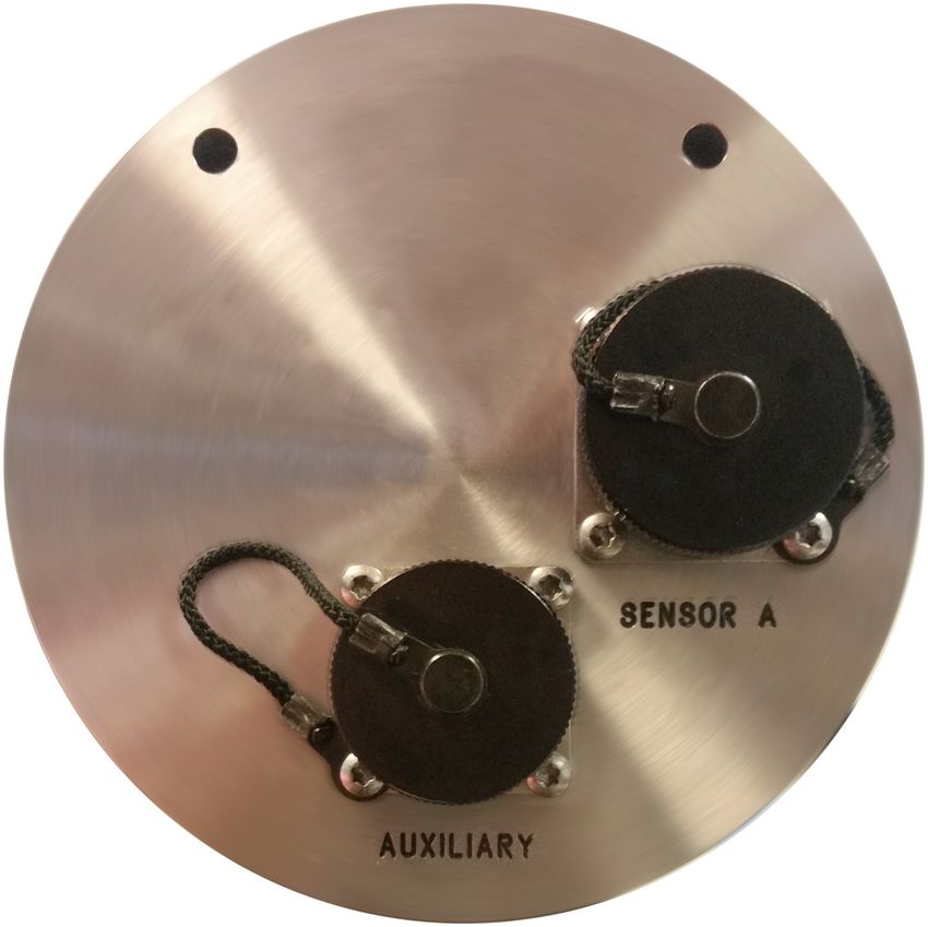
Affinity

       5.1.2 AUXILIARY input..............................................................................................24
    5.2 Digital connections..................................................................................................25
       5.2.1 Connector usage summary..............................................................................25
       5.2.2 Connector Pin-outs..........................................................................................27

6 ADC configuration........................................................................................................33
    6.1 Introduction..............................................................................................................33
       6.1.1 Sample rates and decimation..........................................................................33
    6.2 Data acquisition configuration.................................................................................34
       6.2.1 Station name/locations.....................................................................................35
       6.2.2 Synchronous channels.....................................................................................36
       6.2.3 Multiplexed channels........................................................................................37
       6.2.4 Sensor parameters...........................................................................................39
       6.2.5 Saving and other actions.................................................................................40

7    Sample-clock Timing...................................................................................................41
    7.1 Direct GPS mode.....................................................................................................42
       7.1.1 Configuration....................................................................................................42
       7.1.2 Diagnostics.......................................................................................................43
    7.2 PTP mode................................................................................................................44
       7.2.1 Configuration....................................................................................................45
       7.2.2 Diagnostics.......................................................................................................46

8 Digital I/O.......................................................................................................................47
    8.1 Introduction..............................................................................................................47
    8.2 Lines........................................................................................................................47
       8.2.1 Auxiliary power output......................................................................................47
       8.2.2 Auxiliary power output B..................................................................................47
       8.2.3 Ethernet auxiliary power output.......................................................................47
       8.2.4 GPS Port..........................................................................................................47
       8.2.5 GPS Port detect...............................................................................................47
       8.2.6 System..............................................................................................................48
       8.2.7 Tamper line 0...................................................................................................48
       8.2.8 Tamper lines 1, 2 and 3...................................................................................48
       8.2.9 USB high-power output....................................................................................48
       8.2.10 Internal USB port............................................................................................48
       8.2.11 External USB port..........................................................................................48
       8.2.12 External USB port (peripheral mode).............................................................48

MAN-AFT-0001                                                  3                                             Issue F - June, 2019
Affinity

9 ADC Calibration............................................................................................................49

10 The Borehole Hanger.................................................................................................50
   10.1 Description.............................................................................................................50
   10.2 Installation..............................................................................................................51

11 Revision History..........................................................................................................53

MAN-AFT-0001                                                4                                            Issue F - June, 2019
Affinity                                                                      Preliminary Notes

1          Preliminary Notes

1.1        Proprietary Notice
           The information in this document is proprietary to Güralp Systems Limited and may
           be copied or distributed for educational and academic purposes but may not be used
           commercially without permission.

           Whilst every effort is made to ensure the accuracy, completeness and usefulness of
           the information in the document, neither Güralp Systems Limited nor any employee
           assumes responsibility or is liable for any incidental or consequential damages
           resulting from the use of this document.

1.2        Cautions and Notes
           Cautions and notes are displayed and defined as follows:

                    Caution: A yellow triangle indicates a chance of damage to or failure of
                    the equipment if the caution is not heeded.

                    Note: A blue circle indicates indicates a procedural or advisory note.

1.3        Manuals and Software
           All manuals and software referred to in this document are available from the Güralp
           Systems website: www.guralp.com unless otherwise stated.

1.4        Conventions
           Throughout this manual, examples are given of command-line interactions. In these
           examples, a fixed-width typeface will be used:
                Example of the fixed-width typeface used.
           Commands that you are required to type will be shown in bold:
               Example of the fixed-width, bold typeface.
           Where data that you type may vary depending on your individual configuration, such
           as parameters to commands, these data are additionally shown in italics:
                 Example of the fixed-width, bold, italic typeface.
           Putting these together into a single example:
                 System prompt: user input with variable parameters

MAN-AFT-0001                                5                                Issue F - June, 2019
Affinity Introduction
2 Introduction
Thank-you for purchasing a Güralp Affinity.
The Affinity, a digitiser with combined storage and communications module, is a
flexible and expandable tool for connecting analogue and digital instruments to your
network.
Inside the robust, waterproof, stainless steel casing is a 31-bit, high-fidelity digitiser
with state-of-the-art timing precision and enhanced acquisition module capability.
Designed for data quality and durability, the Güralp Affinity is a stable and robust
Linux-powered unit with on-board storage and networking facilities.
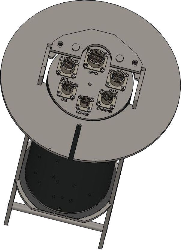
Built for challenging environments, the Güralp Affinity is suitable for post-hole and
bore-hole deployment or can be wall-mounted for vault applications. The Güralp
Affinity can be fully controlled and accessed via a web interface suitable for both
expert and non-expert field staff.
2.1 Applications
• Borehole
• Vault
• Networked Arrays
• Earthquake early-warning systems
MAN-AFT-0001 6 Issue F - June, 2019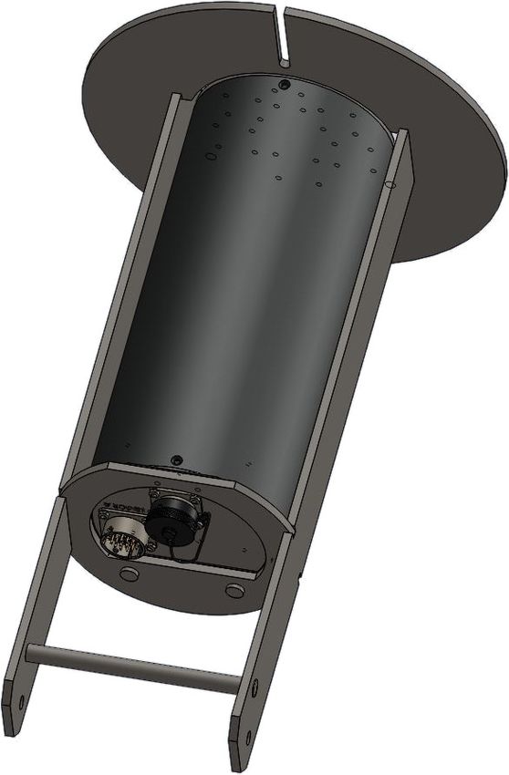
Affinity                                                                           Introduction

2.2        Key features
            •   Four low-noise 31-bit analogue-to-digital conversion (ADC) channels (three
                primary plus one auxiliary)

            •   An eight-channel version is also available

            •   Ultra-low-noise: 139 dB of dynamic range at 100 samples per second

            •   16 environmental multiplexed ADC channels

            •   Triggering/events subsystem capabilities including STA/LTA, level
                (threshold), software triggers, per-channel voting and peer-to-peer network
                voting

            •   Four concurrent output sample rates (continuous or triggered) up to 4,000
                samples per second

            •   UTC time-stamped data using a low-power GPS receiver

            •   Multi-user Linux operating system with full network support

            •   On-board Web server (HTTP and HTTPS) allows full remote configuration of
                digitizer parameters and broadband sensors, including remote lock, unlock
                and centre

            •   16 to 64 GB of on-board storage. Additional connection for external USB
                storage

            •   Built in calibration signal generator: step, sine or broadband

            •   Supports multiple data formats, including GCF, GDI, miniSEED and CD1.1

            •   Specifications independently verified by Sandia Laboratories

MAN-AFT-0001                               7                                Issue F - June, 2019
Affinity                                                            The Affinity documentation

3          The Affinity documentation
           The Affinity documentation comes in two parts: this document and the Platinum
           manual.

           The Güralp Affinity runs the Platinum operating system, which is
           common to many Güralp data acquisition modules, including the
           EAM, the NAM and the legacy DCM. Platinum provides rich web
           and command-line interfaces to configure, control and monitor all
           data storage, protocol conversion, and communications functions.
           These features of the Affinity are all described in the Platinum
           manual, MAN-EAM-0003, which is available from the Güralp
           website in both PDF and HTML form.

           This document, MAN-AFT-0001, partially duplicates the “getting started” section of
           the Platinum manual and then provides details of the features which are unique to
           the Affinity, including configuration and operation of the built in ADCs, the PTP
           timing mode and the connector pin-outs.

           It is strongly recommended that this document is read in conjunction with the
           Platinum manual.

MAN-AFT-0001                                8                               Issue F - June, 2019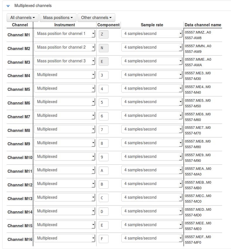
Affinity                                                                          Getting Started

4          Getting Started

4.1        Introduction
           The Güralp Affinity can be configured and monitored either over an Ethernet network
           or via a serial (RS232) line.

           If using a network, the Affinity can be accessed using a web browser or, in character
           mode, using ssh. Instructions for connecting to the network port are given in section
           4.2 on page 9.

           If you prefer to use serial communications, the module can be accessed using a
           terminal emulator. Instructions for connecting via the serial port are given in
           section 4.3 on page 19.

                    Note: We recommend use of the web interface over a network for general
                    configuration and operation.

4.2        Connecting to the network port
           To use the network port, you must first set up a network address. Some networks
           need manual configuration (normally referred to as “static” addressing); others use
           the Dynamic Host Configuration Protocol (DHCP) to allow a DHCP server to
           automatically assign network addresses. If no DHCP server is present, many
           systems will fall back to a randomly-generated “link-local” address (known by
           Microsoft as Automatic Private IP Addressing, or APIPA). Before you can access an
           Affinity over a network, you must set (for static addresses) or discover (if you use
           DHCP) its IP address.

                    Note: If you are setting up a unit in the laboratory for subsequent
                    deployment in the field, you can set up the final network address using the
                    web interface but then over-ride it with a temporary, static network
                    address using the command line. The web-configured address will take
                    effect when the unit is next rebooted.

           4.2.1 DHCP-assigned addresses
           The Affinity is supplied configured for DHCP. If your network uses DHCP to assign
           addresses, simply connect the Affinity to the network and wait a few minutes for the
           process to complete. Your network administrator should then be able to tell you the
           address that has been assigned. If your Affinity has an LCD status display, the
           assigned address will be displayed in it. The LCD display shows lots of information
           so you may have to wait a short time until the IP address scrolls into view.

MAN-AFT-0001                                 9                                Issue F - June, 2019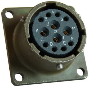
Affinity                                                                          Getting Started

           When using DHCP, it is recommended that the DHCP administrator allocates a fixed
           IP address to the Affinity's MAC address in order to avoid unexpected address
           changes. The MAC address is displayed by the ip command – in the example in
           section 4.2.1.1 on page 10, it is 00:50:c2:40:54:75.

           If you cannot learn the IP address in this way, there are three methods available to
           discover which address has been allocated.

           4.2.1.1 Address discovery – serial connection
           You can connect via a serial port (as described in section 4.3 on page 19) and issue
           the ip command:
                G12345 ~ # ip addr show eth0
                2: eth0:  mtu 1500 qdisc
                pfifo_fast qlen 1000
                   link/ether 00:50:c2:40:54:75 brd ff:ff:ff:ff:ff:ff
                   inet 192.168.0.90/24 brd 192.168.1.255 scope global eth0
                   inet6 fe80:250:c2ff:fe40:5475/64 scope link
                   valid_lft forever preferred_lft forever
                G12345 ~ #

           The key things to note here are the adapter status and the IP address. The first line
           of the output should contain the word UP, confirming that the adaptor has been
           enabled. The IP address that has been assigned is shown on the line beginning inet
           - in this case, it is 192.168.0.90 (with a netmask of 24 bits indicated by /24).

                    Note: With an IP version 6 network, the IP address will be on a line
                    beginning inet6. In practice, most networks today are still IPv4, as in the
                    above example.

           4.2.1.2 Address discovery – Scream's “Detect servers” tool
           Start with the Affinity turned off. Then, from Scream's “Network control” window,
           select the “My Client” tab. Right-click in the server list-box and select “Detect
           servers...” - Scream will then start monitoring DHCP traffic on the local network.
           Power up the Affinity and allow it a minute to boot. When Scream notices a DHCP
           negotiation with an appropriate MAC address, it will display the allocated IP address
           in the window. You can add the Affinity to Scream's list of servers by clicking the
           appropriate button.

           4.2.1.3 Address discovery – GCFPing
           Scream's “GCFPing” feature can send a specially formatted broadcast packet to all
           hosts on the local network. Any GCF servers that see this packet should respond
           with a GCF acknowledgement packet (GCFACKN). Scream displays the IP addresses
           associated with all acknowledgement packets that it receives.

           To use this feature, add a new UDP server with an IP address of 255.255.255.255.
           Right-click the server and select GCFPING from the context menu. A window will

MAN-AFT-0001                                10                                Issue F - June, 2019
Affinity Getting Started
appear as shown below if the ping packet is acknowledged. In the control pane (at
the bottom right of the main window), a GCFACKN line will be printed for every
address that responded to the GCFPING. In the example below, you can see
responses from 192.168.42.135, 192.168.42.98 and 192.168.42.139. These are the
addresses of all GCF servers listening on port 1567 on the local network. One of these
will be your Affinity.
4.2.2 Link-local addresses
Many systems, when configured for DHCP, will generate a random address if no
DHCP server is present. This is known as a “link-local” or APIPA address. For IPv4
networks, it will be in the range 169.254.0.0 to 169.254.255.254 (i.e. on the
169.254.0.0/16 network). For IPv6 networks, it will be in the fe80::/10 network. The
random, host-specific part of the address is derived from the (unique) MAC address,
so there are unlikely to be conflicts between addresses of systems in networks with
small or medium numbers of hosts.
This is useful when, for example, visiting a remote Affinity: A laptop can be plugged
directly into the network port of the Affinity (using a cross-over cable, if necessary)
and, provided both systems are set to use DHCP, both will assign themselves
addresses on the same network. If the laptop is running Scream, you can open
Scream's Network Control window and add a UDP server using the link-local
network's broadcast address, 169.254.255.255, and start communicating immediately.
If the address of the Affinity is required (for, say, web access), this can be read from
Scream's control window, or in the acknowledgement window resulting from a
GCFPING.
MAN-AFT-0001 11 Issue F - June, 2019Affinity Getting Started
The Affinity will search for a DHCP server once every minute and, should one
become available, it will ask it for a new address.
4.2.3 Assigning a static IP address
If you wish to configure a static IP address, you must first connect to the command
line via a serial port. This process is described in detail in section 4.3 on page 19.
4.2.3.1 Assigning a static IP address using net-setup
Once logged in, issue the following command:
G12345 ~ # net-setup
Note: This command relies on the Affinity understanding what type of
terminal emulator you are using. If the display is corrupted and not
usable, set the TERM variable (see the Platinum manual for details), or
simply power-cycle the Affinity and use the ip command (see section
4.2.3.2 on page 13) instead.
The following screen is displayed:
Using the and keys (or, on some systems, depending on your terminal type,
the mouse), select whether you wish to use DHCP or static addressing. The red
letters in the display indicate short-cut keys so, for example, you can, key to
select DHCP or to select static addressing. Use the ENTER key to confirm your
choice. If you do not wish to make a change, use the key to select “Cancel”
and then key ENTER to close the net-setup tool and return you to the command
prompt.
MAN-AFT-0001 12 Issue F - June, 2019Affinity Getting Started
If you select static addressing, the following screen is displayed:
The IP address field must be populated with a valid IP address in CIDR notation. If
you know the netmask but not the corresponding CIDR notation, use the information
on screen as a guide or search the web for an on-line converter.
If your network has a router which acts as a gateway to the Internet or to other
networks, use the key (or, on some systems, the mouse) to move to the
“Gateway/router” field and enter the address of the gateway in standard, dotted-quad
notation (e.g. 10.0.0.1).
If your network has a DNS (domain-name service) server, sometimes called a name-
server, use the key (or, on some systems, the mouse) to move to the “Primary
DNS server” field and enter the address of the name-server in standard, dotted-quad
notation (e.g. 10.0.0.5).
Note: If your network is connected to the Internet but you do not know the
name of your DNS server, ask your Internet Service Provider for the correct
address to use or enter 8.8.8.8, which is a free, public DNS server
operated by Google Inc.
Use the ENTER key to confirm your choice and reconfigure the network. If you do not
wish to make a change, use the key to select “Cancel” and then key ENTER to
close the net-setup tool and return you to the command prompt.
4.2.3.2 Assigning a static IP address using the ip command
The ip command is an alternative to net-setup. You may wish to use it if
• you want to configure a temporary address without updating the
configuration files
• you cannot use the net-setup utility for any reason
MAN-AFT-0001 13 Issue F - June, 2019Affinity Getting Started
• you are very familiar with the linux command line
Log in as normal and then issue the following command:
G12345 ~ # ip addr add 192.168.0.1/24 dev eth0
replacing the example IP address (192.168.0.1/24 in the example above) with the
required value. It must be specified in CIDR format, where the actual address is
followed by the number of bits of the network mask. The above example uses
192.168.0.1 with a netmask of 255.255.255.0 (24 bits of network address). A PC
connected to this network could communicate with the Affinity if it was configured
to use an IP address of (for example) 192.168.0.2 with a matching netmask of
255.255.255.0.
Note: IP addresses assigned using this method will be lost if the unit is
rebooted. To permanently assign an IP address, use net-setup (see
section 4.2.3.1 on page 12), the web interface or gconfig. Please see the
Platinum manual for more details.
If you wish to connect to the Affinity from a PC, they must either both be on the same
physical network and have the same network address (usually the first three
numbers of the IP address) or be able to connect to each other via routers.
In the latter case, you will need to tell the Affinity the address of its default router
(also known as the gateway). Issue the command:
G12345 ~ # ip route add default via 192.168.0.254
substituting the address of your network's default router in place of the example
address (192.168.0.254) shown.
If you wish to be able to access your Affinity across the Internet, perform firmware
upgrades or access GSL remote support, you will also need to configure a default
router as described in the preceding paragraph.
Note: Both the static IP address and any route configured in this way are
temporary and will persist only until the Affinity is rebooted or powered
off. Refer to the Platinum manual for information about configuring
permanent static IP addresses and routes.
If you wish your Affinity to initiate connections with remote systems across the
Internet, or to be able to access firmware upgrades, you need to configure a DNS
server (also known as a name-server). If you do not know the address of your DNS
server, your Internet Service Provider (ISP) will be able to tell you. You can also use
8.8.8.8, which is a free, public DNS server operated by Google Inc.
Enter the command
G12345 ~ # echo "nameserver 8.8.8.8" >> /etc/resolv.conf
substituting the address of the required DNS server in place of the example address
(8.8.8.8) shown in the example above.
MAN-AFT-0001 14 Issue F - June, 2019Affinity Getting Started
4.2.4 Connecting to the web interface
The Platinum firmware on the Affinity provides a web interface for configuration and
control of the module and connected equipment. While there are other methods of
connecting, the web interface is recommended.
Once the IP address of the Affinity has been set or determined, enter it into the
address bar of a web browser to connect to the module's web interface . The
examples below are for an Affinity address entered into Firefox and Internet
Explorer:
The web interface will initially show a status display and a brief menu which
contains an option to log in. Click on the link and enter the default user-name of
root and password of guralp3.
If you are connecting to the Affinity over a network that you consider insecure (such
as the Internet), it is recommended that you use the HTTPS (secure HTTP) protocol,
which uses TLS to encrypt the link. Simply change the http:// prefix to https://
in the browser's address bar. Most browsers will complain that the certificate cannot
be verified: This is not a problem: simply press the “accept” button to proceed. The
link will then be encrypted and nobody will be able to “sniff the wire” in an attempt
to discover passwords and other data.
Once connected and logged in, you will be presented with the main summary screen
and a much larger menu. The summary screen contains general information about
the status and health of the connected modules and equipment.
The exact contents and layout of this screen will vary depending on the
configuration of both the Affinity and of any attached devices.
See the Platinum manual for information on using the web interface.
4.2.4.1 Connection trouble-shooting
If the browser fails to connect, the most likely explanation is that the machine
running the browser does not have working network communications to and from
the Affinity. This can be verified by “pinging” the IP address of the browser from the
command line of the Affinity:
G12345 ~ # ping -c3 192.168.0.2
PING 192.168.0.2 (192.168.0.2): 56 data bytes
64 bytes from 192.168.0.2: seq=0 ttl=63 time=2.284 ms
64 bytes from 192.168.0.2: seq=1 ttl=63 time=1.129 ms
64 bytes from 192.168.0.2: seq=2 ttl=63 time=1.944 ms
--- 192.168.42.1 ping statistics ---
3 packets transmitted, 3 packets received, 0% packet loss
round-trip min/avg/max = 1.129/1.785/2.284 ms
G12345 ~ #
MAN-AFT-0001 15 Issue F - June, 2019Affinity Getting Started
To resolve this class of problem, ensure that the cables are functioning (which can
be verified by checking the diagnostic lights on most network switches/hubs) and
double-check that the PC and Affinity are on the same subnet (which means the
CIDR suffices must match and the first sections of the IP addresses – as defined by
the CIDR suffices - must also match).
The website http://en.wikipedia.org/wiki/IP_address has some useful information
for those for whom sub-networking is unfamiliar.
4.2.5 Connecting to the command line using SSH
SSH (Secure SHell) is the most flexible way to control an Affinity, but it is less
friendly than using the web interface. It is possible to configure more advanced
operations using SSH but the majority of control and configuration tasks can be
achieved most easily through the web interface.
SSH is shipped as standard with most Linux distributions and is available for
Windows as part of the free terminal emulation package PuTTY, which is available
from http://www.chiark.greenend.org.uk/~sgtatham/putty/
4.2.5.1 SSH connections using the ssh program (Linux PCs)
To use SSH, you must know or discover the IP address of the unit, as described in the
previous section. Once you have the IP address, issue the ssh command on the PC
you are using:
mypc$ ssh root@192.168.0.1
Replace 192.168.0.1 with the IP address of the Affinity.
The first time you use SSH to connect to any host, you will be asked to verify the
“host key”. This is normal but, if you are ever asked this again, it means that either
the host key of the Affinity has changed – perhaps because of a firmware upgrade –
or there is a network address conflict or, worse, a security problem on your network.
user@mypc:~$ ssh root@192.168.0.1
The authenticity of host '192.168.0.1 (192.168.0.1)' can't
be established.
RSA key fingerprint is
62:a6:70:29:d4:1a:db:5a:75:6e:96:13:54:f5:a9:d9.
Are you sure you want to continue connecting (yes/no)? yes
Warning: Permanently added '192.168.0.1' (RSA) to the list
of known hosts.
root@192.168.0.1's password:
G12345 ~ #
You will be prompted for a password; the default password is guralp3. Note that no
characters will be echoed to the screen as you type the password.
Once connected, you will be presented with a shell prompt which is ready to accept
commands.
MAN-AFT-0001 16 Issue F - June, 2019Affinity Getting Started
When you are finished with your SSH session and want to disconnect, enter exit at
the command line, or type + . There are a number of escape sequences for
controlling the session, all of which begin with a tilde ('~') so, if you need to send a
tilde character to the Affinity, type two tildes consecutively. For more information,
see the section on “Escape Characters” in the manual at
http://man-wiki.net/index.php/1:ssh
Note: If you plan to use ssh regularly to communicate with your Affinity,
you can configure the system to bypass the password prompt when
logging in from a list of pre-authorised computer/user combinations. This
involves generating a unique key-pair (for the user and PC which will
access the Affinity) and then copying the public half of the key-pair to the
Affinity. This can be more secure than passwords and is fully
documented at http://suso.org/docs/shell/ssh.sdf. For details about
uploading your keys to the Affinity, see the Platinum manual.
4.2.5.2 SSH connections using PuTTY (Windows PCs)
To use PuTTY, you must first know or discover the IP address of the unit, as described
in the previous sections. Once you have the IP address, start PuTTY by choosing it
from the “Start” menu or double-clicking on its icon. You will be presented with the
following screen:
Enter the IP address of the Affinity into the Host Name (or IP address) field, check
that SSH is selected as the Connection type and then click the button.
MAN-AFT-0001 17 Issue F - June, 2019Affinity Getting Started
The first time you use SSH to connect to any host, you will be asked to verify the
“host key”:
This is normal (simply click to dismiss the dialogue) but, if you are ever
asked this again, it means that either the host key of the Affinity has changed –
perhaps because of a firmware upgrade – or there is a network address conflict or,
worse, a security problem on your network.
You will now be prompted for a login name: the default is root. Type this at the
prompt and press the ENTER key. You will next be prompted for a password; the
default password is guralp3. Note that no characters will be echoed to the screen
as you type the password.
Once connected, you will be presented with a shell prompt which is ready to accept
commands. The shell prompt contains the serial number of the Affinity.
When you are finished with your SSH session and want to disconnect, type “exit” at
the command line, or + .
PuTTY allows you to save multiple sessions, along with a default login identity and
screen colours for each. See the PuTTY manual for more details.
MAN-AFT-0001 18 Issue F - June, 2019Affinity Getting Started
Note: If you plan to use ssh regularly to communicate with an Affinity, you
can configure the system to bypass the password prompt when logging in
from a list of pre-authorised computer/user combinations. This involves
generating a unique key-pair (for the user and PC which will access the
Affinity) and then copying the public half of the key-pair to the Affinity.
This can be more secure than passwords and is fully documented at
http://suso.org/docs/shell/ssh.sdf. For details about uploading your keys
to the Affinity, see the Platinum manual.
4.3 Connecting to the Serial Console
The serial console of the Affinity is accessed using the GPIO connector. The Affinity
is shipped with a blue serial cable, terminating in a female DE9 connector, which can
be used for console connections.
Once you have connected the serial cable, you can run either Scream or a terminal
emulator to interact with the Affinity.
4.3.1 Using Scream
Select Terminal... from the File menu. A window will open, from where you can
select the correct serial port:
Set the Baud Rate to 38400, as shown, and, once the Affinity and computer are
communicating properly, an emulation window will open and you will see the Login:
prompt. If it does not appear immediately, press the ENTER key a few times.
Note: If a terminal session has just been closed, it can take up to ten
seconds for a new session to start.
MAN-AFT-0001 19 Issue F - June, 2019Affinity Getting Started
4.3.2 Using a terminal Emulator
You are free to use whatever terminal emulation software you wish. Common
choices are applications such as minicom on Linux or PuTTY on Microsoft Windows.
See the Platinum manual for more information.
Configure your emulation software to use the correct serial port. Set the line speed
(Baud rate) to 38,400 and the communication parameters to eight data bits, no parity
bits and one stop bit. This combination is commonly referred to as “8-N-1”. Turn off
all hardware flow control (RTS/CTS and/or DSR/DTR should not be used). Turn off all
software flow control (XON/XOFF should not be used).
Once the emulator is connected, you will see a Login: prompt. If it does not appear
immediately, press the ENTER key a few times.
Note: If a terminal session has just been closed, it can take up to ten
seconds for a new session to start.
4.3.3 Logging in
The Affinity is shipped with a default user-name of root and password of guralp3.
(Additional users with controlled capabilities can be added if required).
Enter the user name and password. Note that nothing will display on the screen
when typing the password. You will then be presented with a shell prompt, which
will accept commands as shown in the image below:
G12345 login: root
Password:
G12345 ~ #
The output may vary slightly due to the configuration of the unit. In particular, the
Affinity name, as displayed in the prompt (G12345 in this example), will be different.
4.4 Viewing data
Once you know the IP address of the Affinity, it is simple to view the data using
Güralp's Scream! Software. To do this:
1. Start Scream! And choose “Network Control” from the “Windows” menu (or
key + , which has the same effect).
2. Switch to the “My Client” tab.
3. Tick the “Receive UDP Data” check-box to start Scream! listening.
MAN-AFT-0001 20 Issue F - June, 2019Affinity Getting Started
4. Right-click anywhere in the Servers list box, and select “Add UDP Server…” (or
key , which has the same effect). Enter the IP address of the Affinity.
Note: If you have already configured the Affinity's Scream server
to use a non-standard UDP port, type a colon and the required port
number after the IP address, e.g. 192.168.0.14:1568. The
default port is 1567: this is used if no port number is entered.
5. Test communications by right-clicking on the newly-added server, and
selecting GCFPING from the context menu (or by keying + , which
has the same effect). A message appears in the Control pane logging the ping
being sent. If communication is good and the server accepts client requests,
you will receive an acknowledgement message (GCFACKN) from the server.
This will also appear in the Control pane.
6. Request data by right-clicking on the server and selecting GCFSEND:B from
the context menu (or by keying + , which has the same effect).
Streams should soon begin to appear in Scream!'s main window.
Note: The steps above can be repeated as many times as
necessary to pull data from several servers. Scream! remembers
all the network settings when it exits, and automatically tries to
reconnect when you start it again.
7. Switch to the main window and select the streams that you wish to view by
holding the key while clicking each. Once all desired streams are
selected, key Enter to open a WaveView window showing live data streaming
from the Affinity.
For more details, please see the Scream! Manual, MAN-SWA-0001, which can be
downloaded from http://www.guralp.com/documents/MAN-SWA-0001.pdf
MAN-AFT-0001 21 Issue F - June, 2019Affinity Connections
5 Connections
5.1 Analogue connections
The analogue connector panel of the Affinity has one or two SENSOR connectors
(depending on the model) and an AUXILIARY connector. The pin-outs for these
connectors are given in the following sections.
Note: Early models did not provide power via the AUXILIARY connector.
The auxiliary connector provides a differential input to the fourth full-rate channel
and single-ended inputs to ten of the sixteen multiplexed inputs. (The other six are
connected internally for use as mass position channels on the main SENSOR A and
SENSOR B inputs.)
MAN-AFT-0001 22 Issue F - June, 2019Affinity Connections
5.1.1 SENSOR A and SENSOR B
This is a standard twenty-six-pin bayonet plug,
conforming to MIL-DTL-26482 (formerly MIL-C-26482).
A typical part-number is 02E-16-26P although the
initial “02E” varies with manufacturer.
Suitable mating connectors have part-numbers like
***-16-26S and are available from Amphenol, ITT
Cannon and other manufacturers.
Pin Function Pin Function
Vertical velocity non-inverting
A P Calibration signal
input
B Vertical velocity inverting input R Vertical calibration enable
C N/S velocity non-inverting input S N/S calibration enable
D N/S velocity inverting input T E/W calibration enable
E E/W velocity non-inverting input U Centre
F E/W velocity inverting input V Sensor RS422 Rx-
G Vertical mass position input W Unlock
H not connected X Lock
J N/S mass position input Y Digital (logic signal) ground
K Busy indicator LED Z Sensor RS422 Tx+ / RS232 Tx
L E/W mass position input a Sensor RS422 Rx+ / RS232 Rx
M Sensor RS422 Tx- b Power 0 V & digital ground
Power output +9 to +36 VDC
N Signal ground c
(via 550 mA poly-fuse)
Wiring details for the compatible socket, ***-16-26S,
as seen from the cable end (i.e. during assembly).
MAN-AFT-0001 23 Issue F - June, 2019Affinity Connections
5.1.2 AUXILIARY input
This is a standard nineteen-pin bayonet plug,
conforming to MIL-DTL-26482 (formerly MIL-C-26482).
A typical part-number is 02E-14-19P although the initial
“02E” varies with manufacturer.
Suitable mating connectors have part-numbers like
***-14-19S and are available from Amphenol, ITT
Cannon and other manufacturers.
Pin Function Pin Function
SENSOR B auxiliary / calibration SENSOR A and multiplexed
A L
channel non-inverting (+ve) inputs signal ground
SENSOR B auxiliary / calibration
B M Multiplexed input E / Aux 10
channel inverting–ve
C SENSOR B Signal ground N Digital ground
D Multiplexed input A / Aux 6 P Power output -ve
E Multiplexed input B / Aux 7 R Multiplexed input F / Aux 11
F Multiplexed input C / Aux 8 S Multiplexed input G / Aux 12
G Power output +ve T Multiplexed input H / Aux 13
H Multiplexed input D / Aux 9 U Multiplexed input J / Aux 14
SENSOR A auxiliary / calibration
J V Multiplexed input K / Aux 15
channel non-inverting (+ve)
SENSOR A auxiliary / calibration
K
channel inverting–ve
Wiring details for the compatible socket,
***-14-19S, as seen from the cable end (i.e.
during assembly).
Note: Early models did not provide power via the AUXILIARY connector.
MAN-AFT-0001 24 Issue F - June, 2019Affinity Connections
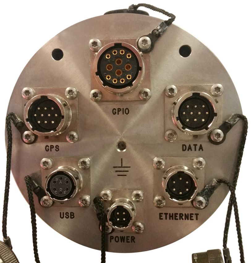
5.2 Digital connections
The Affinity has six connectors on the digital connection panel, the pin-outs and
uses of which are described in this section.
5.2.1 Connector usage summary
5.2.1.1 DATA
The DATA port is a general-purpose serial port and it can also be used as alternative
power input. It provides a command-line terminal running at 115,200 Baud in the
default configuration but it can also be used for GCF output (suitable for serial
connection to Scream!), PPP network connections, inbound GCF (from a digital
instrument, for example), NMEA functions, TCP serial conversion, a modem
answering service or as a recorder to store and forward data from any instrument
with a serial output.
MAN-AFT-0001 25 Issue F - June, 2019Affinity Connections
5.2.1.2 ETHERNET
The NET port is a 100BASE-TX Ethernet connection. The supplied cable supports
connection to a hub, switch or router. If direct connection to a PC or laptop is
desired, an optional cross-over cable can be ordered.
5.2.1.3 POWER
The POWER connector functions as the main power input and also provides a
switched power outlet for external equipment.
5.2.1.4 USB
The USB port allows connection of an external USB storage device for data
collection. It is also possible to perform firmware upgrades using this port in
situations where internet access is not available.
5.2.1.5 GPS
The GPS port allows connection of a GSL GPS receiver for use as a timing source for
time-stamping seismic data. An additional serial port, ttySA2, is also available on
this connector. It can be used for any of the functions available from the DATA
connector (see section 5.2.1.1, above).
5.2.1.6 GPIO
The GPIO (General Purpose Input/Output) port fulfils two functions: it provides a
serial console to the Affinity, which can be used for monitoring, configuration and
control; and it provides a number of tri-state lines which can be used to control or
monitor external equipment. One application is as tamper detection lines, which
can be connected to external switches and monitors to form part of a secure
installation.
Note: Early models provided access to the internal USB storage via this
connector. This functionality is no longer available.
MAN-AFT-0001 26 Issue F - June, 2019Affinity Connections
5.2.2 Connector Pin-outs
5.2.2.1 DATA
This is a standard ten-pin bayonet plug, conforming to
MIL-DTL-26482 (formerly MIL-C-26482). A typical
part-number is 02E-12-10P although the initial “02E”
varies with manufacturer.
Suitable mating connectors have part-numbers like
***-12-10S and are available from Amphenol, ITT
Cannon and other manufacturers.
Pin Function
A Power input, 0 V
B Power input +10 to +28 Volts DC
C RS232 CTS
D RS232 RTS
E External trigger output
F External trigger output
G RS232 ground
H External trigger input
J RS232 receive
K RS232 transmit
Wiring details for the compatible socket, ***-12-10S,
as seen from the cable end (i.e. during assembly).
MAN-AFT-0001 27 Issue F - June, 2019Affinity Connections
5.2.2.2 ETHERNET
This is a standard six-pin bayonet plug, conforming to
MIL-DTL-26482 (formerly MIL-C-26482). A typical
part-number is 02E-10-06P although the initial “02E”
varies with manufacturer.
Suitable mating connectors have part-numbers like
***-10-06S and are available from Amphenol, ITT
Cannon and other manufacturers.
Pin Function
A Ground
B Data transmit +ve (RJ45 pin 1)
C Data receive +ve (RJ45 pin 3)
D Ethernet auxiliary power output (see section 8.2.3 on page 47)
E Data receive –ve (RJ45 pin 6)
F Data transmit –ve (RJ45 pin 2)
Wiring details for the compatible socket, ***-10-06S,
as seen from the cable end (i.e. during assembly).
MAN-AFT-0001 28 Issue F - June, 2019Affinity Connections
5.2.2.3 POWER
This is a standard four-pin bayonet plug, conforming to
MIL-DTL-26482 (formerly MIL-C-26482). A typical
part-number is 02E-08-04P although the initial “02E”
varies with manufacturer.
Suitable mating connectors have part-numbers like
***-08-04S and are available from Amphenol, ITT
Cannon and other manufacturers.
Pin Function
A Ground
B Power input +10 to +28 Volts DC
C Not connected
D Auxiliary power output (see section 8.2.1 on page 47)
Wiring details for the compatible socket, ***-08-04S,
as seen from the cable end (i.e. during assembly).
MAN-AFT-0001 29 Issue F - June, 2019Affinity Connections
5.2.2.4 USB
This is a standard six-pin bayonet socket, conforming
to MIL-DTL-26482 (formerly MIL-C-26482). A typical
part-number is 02E-10-06S although the initial “02E”
varies with manufacturer.
Suitable mating connectors have part-numbers like
***-10-06P and are available from Amphenol, ITT
Cannon and other manufacturers.
Pin Function
A +5 Volt DC (USB Type A pin 1) (see section 8.2.11 on page 48)
B Data –ve (USB Type A pin 2)
C Data +ve (USB Type A pin 3)
D 0 V (USB Type A pin 4)
E Shielding
F “USB on-the-go” detection (see section 8.2.12 on page 48)
Wiring details for the compatible plug, ***-10-06P,
as seen from the cable end (i.e. during assembly).
MAN-AFT-0001 30 Issue F - June, 2019Affinity Connections
5.2.2.5 GPS
This is a standard ten-pin bayonet plug, conforming to
MIL-DTL-26482 (formerly MIL-C-26482). A typical
part-number is 02E-12-10P although the initial “02E”
varies with manufacturer.
Suitable mating connectors have part-numbers like
***-12-10S and are available from Amphenol, ITT
Cannon and other manufacturers.
The pin-out is the same as the GPS input of a DM24 digitizer.
Pin Function
A Power 0 V
B Power +V
C 1pps signal
D not connected
E Digitizer console transmit
F Digitizer console receive
G RS232 ground
H Digitizer console ground
J RS232 transmit to GPS
K RS232 receive from GPS
Wiring details for the compatible socket, ***-12-10S,
as seen from the cable end (i.e. during assembly).
MAN-AFT-0001 31 Issue F - June, 2019Affinity Connections
5.2.2.6 GPIO
This is a standard twelve-pin bayonet socket,
conforming to MIL-DTL-26482 (formerly MIL-C-26482).
A typical part-number is 02E-14-12S although the initial
“02E” varies with manufacturer.
Suitable mating connectors have part-numbers like
***-14-12P and are available from Amphenol, ITT
Cannon and other manufacturers.
Pin Function
A Not connected
B Not connected
C Not connected
D Anti-tamper line 3 (see section 8.2.8 on page 48)
E Anti-tamper line 2 (see section 8.2.8 on page 48)
F Anti-tamper line 1 (see section 8.2.8 on page 48)
G Console transmit (RS232 TXD)
H Console receive (RS232 RXD)
J Not connected
K Not connected
F Anti-tamper line 1 (see section 8.2.8 on page 48)
M Ground
Wiring details for the compatible plug,
***-14-12P, as seen from the cable end (i.e.
during assembly).
Note: Early models provided access to the internal USB storage via this
connector. This functionality is no longer available.
MAN-AFT-0001 32 Issue F - June, 2019Affinity ADC configuration
6 ADC configuration
6.1 Introduction
The Güralp Affinity contains one or two ADC cards. Each ADC card provides four
full-featured, synchronous ADC channels and a single ADC with an input multiplexor
that can handle eight different channels at a lower resolution. Because this style of
ADC is unique to the Affinity, its configuration is not covered in the Platinum
manual.
6.1.1 Sample rates and decimation
Unlike other Güralp digitisers, the Affinity has a simple decimation model which
uniquely maps each output sample rate to a single filter chain configuration. The
available output rates (and associated latencies), are shown below:
MAN-AFT-0001 33 Issue F - June, 2019Affinity ADC configuration
This arrangement offers the lowest possible latency for each output sampling rate
without sacrificing quality.
6.2 Data acquisition configuration
The configuration interface can be used to configure the ADC in an Affinity, the
digitiser module in a DM24SxEAM or any serially attached Güralp digitiser, such as a
Güralp DM24 or CD24, or digital instrument. The interface for external digitisers and
digital instruments is described in the Platinum manual. This section describes the
interface for the ADC in an Affinity.
To configure the ADC using the web interface select:
Configuration → Data handling → Data acquisition
If external digitisers and digital instruments are present, a list will be displayed
from which you can select the digitiser to configure. If there are no external
digitisers, the ADC configuration screen appears immediately.
Note: To control an attached instrument, as opposed to configuring the
ADC, please see the Sensor Control section of the Platinum manual.
The first time that this screen is accessed, a warning is displayed:
This is normal and, once a configuration has been saved, it will not be shown again.
The ADC configuration screen has three parts: “Station name/locations”,
“Synchronous channels” and “Multiplexed channels”. Each section can be
expanded (shown) or contracted (hidden) by clicking the blue arrow symbols, and
.
MAN-AFT-0001 34 Issue F - June, 2019Affinity ADC configuration
6.2.1 Station name/locations
Use this section to configure the logical instruments which are being associated
with the ADCs. Each row represents a logical instrument and additional rows can be
added as required using the button.
For each logical instrument, the following attributes are displayed:
• SEED name – these values are used for naming channels transmitted over
SEEDlink, CD1.1 and some other protocols.
◦ Station name – this is initially based on the serial number of the Affinity
but can be altered here as desired.
◦ Channel name – this is automatically determined from the Instrument
type
◦ Network code – this can be entered if desired or left blank if not required
◦ Location – this field is automatically populated but can be over-ridden if
desired
• GCF name – these values are used for naming channels transmitted using
GCF protocols, such as Scream and BRP, or GDI.
◦ GCF system ID – this is initially based on the serial number of the Affinity
but can be altered here as desired.
◦ GCF serial/stream ID – this field is automatically populated but can be
over-ridden if desired
• Instrument type – The instrument type can be chosen from the extensive
menu which is displayed when you click the button.
MAN-AFT-0001 35 Issue F - June, 2019Affinity ADC configuration
6.2.2 Synchronous channels
For each of the four main synchronous channels, this section allows you to select the
component letter used for stream naming, the Channel gain to be applied and the
sample rate(s) to be generated. The default, recommended component lettering for a
single triaxial velocity sensor is shown above.
Channel gains from unity to ×64 are available in binary steps. To change a channel
gain, click the appropriate button. The following screen is displayed:
MAN-AFT-0001 36 Issue F - June, 2019Affinity ADC configuration
The desired gain can then be selected from the drop-down menu and saved to the
configuration with the button.
One or more sample rates can be selected for each synchronous channel. Each
selected sample rate appears in a separate row at the bottom of the table and output
from each channel at that sample rate can be enabled or disabled using the check-
box.
The automatically-generated SEED names (in S.C.N.L. format) are displayed beside
each check-box, above the automatically-generated GCF names.
To add, delete or change the sample rates, click the button. The
following screen is displayed:
Use the check-boxes to select which sample rates are to be displayed in the main
Synchronous channels screen, and then click the button to return to
the main screen.
6.2.3 Multiplexed channels
The Multiplexed channels section displays one row for each available multiplexed
channel. The display can be filtered to show subsets of the channels:
• The button shows only channels designated as mass position
channels, typically M1, M2 and M3.
• The button hides the mass position channels and shows all
others.
MAN-AFT-0001 37 Issue F - June, 2019Affinity ADC configuration
• The button displays every channel.
For each multiplexed channel, the associated instrument and component are shown,
along with a drop-down menu for selecting the sample rate and the associated
automatically-generated SEED name (in S.C.N.L. format) and GCF name.
The available sample rates for multiplexed channels are 1, 2, 4, 5, 8 or 10 samples per
second. Each channel can also be switched off using the “Sample rate” drop-down
menu.
MAN-AFT-0001 38 Issue F - June, 2019Affinity ADC configuration
6.2.4 Sensor parameters
The sensor parameters table is accessed by clicking the link below the multiplexed
channels table:
This opens the sensors parameters table, which has one row for each input channel.
Each row has:
• a field for Sensor gain;
• a check-box which controls whether the gain is applied or not;
• a field for sensor offset;
• a check-box which controls whether the offset is applied or not; and
• a label showing the associated output channel name.
Values entered into the Sensor Gain fields will be reported in the associated
channel's meta-data as "sensor-gain" or, if applied to the digitiser input before any
sensor offset as "sensor-gain-applied". Similarly, values entered into the Offset
fields will be reported in meta-data as "sensor-offset" or, if applied to the digitiser
input, as "sensor-offset-applied".
MAN-AFT-0001 39 Issue F - June, 2019Affinity ADC configuration
Note: Any specified offset is subtracted after the specified gain has been
applied.
Data entered into this table are stored in the file /etc/das-in/das-in.local.
6.2.5 Saving and other actions
When all required changes have been made, scroll back to the top of the screen and
click the button. The following screen is displayed:
The configuration is saved and the new settings take effect immediately. Click
to continue. The warning
is removed and not displayed again.
The button displays the following menu:
From this menu:
• The button abandons all changes that have
been made to this form since the last save and resets the form to match the
saved configuration.
• The button resets the contents of the form to
the factory defaults.
• The button saves a configuration template file
and uses your browser's normal file download facility to allow you to save it to
your PC. This feature is intended for use in a future development.
• The button is currently unimplemented. This
feature is intended for use in a future development.
MAN-AFT-0001 40 Issue F - June, 2019Affinity Sample-clock Timing
7 Sample-clock Timing
All Platinum systems offer a choice of timing modes. The modes available on the
Affinity are:
• Direct GPS – the sample clock is trained directly to GPS time, as determined
from an attached GPS receiver;
• PTP – the sample clock is trained to system time, as synchronised using the
Precision Time Protocol (PTP);
• NTP – the sample clock is trained to system time, as synchronised using the
Network Time Protocol (NTP);
• Manually set – the sample clock is manually set by the operator; and
• CD24/DM24 with GPS – the sample clock is trained to system time, which is
synchronised to incoming Universal Status Packets (USP) from an attached
CD24 or DM24 digitiser (which is, in turn, assumed to be synchronised to GPS
time).
For the Affinity, the recommended timing mode is Direct GPS. This offers the
highest accuracy of all available options.
The Platinum manual describes Direct GPS mode, NTP mode, Manual mode and
CD24/DM24 with GPS modes. This chapter duplicates the Direct GPS mode section
and provides information about PTP mode, which is unique to the Affinity.
To configure the Timing mode using the web interface select:
Configuration → Data handling → Timing
The resulting screen first offers a button, , which allows the
display time-zone to be set from an extensive list. Note that this does not affect the
sample clock – just times and dates displayed in the web interface and log-files.
Clicking the button shows the following window.
Select the required time-zone and then click to save your choice.
MAN-AFT-0001 41 Issue F - June, 2019You can also read