Siemens Prisma 3T MRI Scanner User Guide - Ahmanson-Lovelace Brain Mapping Center University of California, Los Angeles
←
→
Page content transcription
If your browser does not render page correctly, please read the page content below
Revision Date: 9/23/2021

    Siemens Prisma 3T MRI Scanner
              User Guide

Ahmanson-Lovelace Brain Mapping Center
  University of California, Los Angeles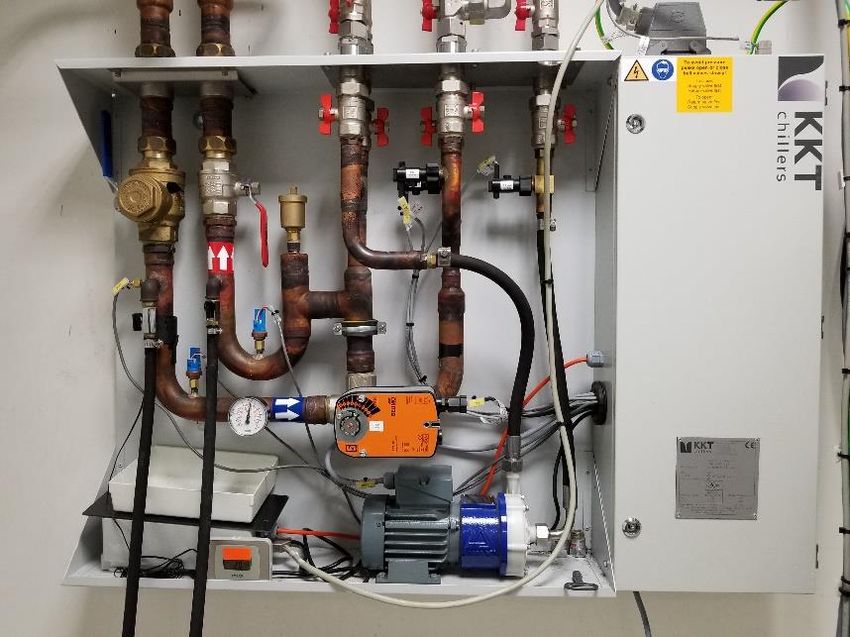
Revision Date: 9/23/2021

BMC Contacts ............................................................................................................................... 1
Scanner Operation ........................................................................................................................ 2
         • How to do a “Standby” Reboot ............................................................................... 2
         • How to Turn Off the MRI Scanner/Computer (Full Shutdown)............................. 3
         • How to Turn on the MRI Scanner/Computer ......................................................... 4
         • MR Scanner Error Save Log ................................................................................... 4
         • How to Check the System Manager........................................................................ 5
         • How to Restart the Coldhead .................................................................................. 6
         • How to Reboot the Chiller ...................................................................................... 7
Re-import DICOM Data .............................................................................................................. 8
         • How to Map a Dicom Network Folder on the Scanner Console ............................ 8
Export and Save Raw Data Files (.RDA and Raw).................................................................... 9
         • How to Map a Non-Dicom Network Folder on the Scanner Console .................... 9
         • How to Create a Spectroscopy .RDA File .............................................................. 9
         • How to Transfer Raw Data Using TWIX Software .............................................. 10
How to Burn a CD From The Scanner Console ....................................................................... 11
Prisma Cleanup Procedures....................................................................................................... 12
         • General Cleanup Guidelines ................................................................................. 12
Squeeze Ball/Button Alarm ........................................................................................................ 13
         • What to do when the Squeeze Ball/Button Alarm Goes Off ................................ 13
         • Reset the Table ...................................................................................................... 13
How to Run the Daily Stability Warmup ................................................................................. 14
         • Setting up the Phantom ......................................................................................... 14
         • Register Phantom .................................................................................................. 14
         • Running Scans ...................................................................................................... 14
         • Registration Pictures ............................................................................................. 15
How to Run the ABCD Phantom QA ........................................................................................ 16
         • Setting up the Phantom ......................................................................................... 16
         • Register the Phantom ............................................................................................ 17
         • Running Scans ...................................................................................................... 18
         • Registration Pictures ............................................................................................. 19
How to Trigger Test Stimuli/Tasks ........................................................................................... 20
         • Setting up the Phantom ......................................................................................... 20
         • Register Phantom .................................................................................................. 20
         • Running Scans ...................................................................................................... 20
         • Registration Pictures ............................................................................................. 21
Coil Warnings - Protocol Was Fixed......................................................................................... 22
         • Main Reasons for Coil Warnings.......................................................................... 22
         • Anterior or Posterior Protocol Fixed Warning Messages ..................................... 22
         • Resolution ............................................................................................................. 22
         • Wrong Coil Protocol Fixed Warning Messages ................................................... 22
Prisma VE11C Software Bugs ................................................................................................... 24
         • AutoAlign Re-Run Failure.................................................................................... 24
         • AP/PA Copy Reference Issue ............................................................................... 24
         • Reconstruction Error (aka Blob error) .................................................................. 25
Prisma VE11C Scanner Warnings/Messages/Errors .............................................................. 26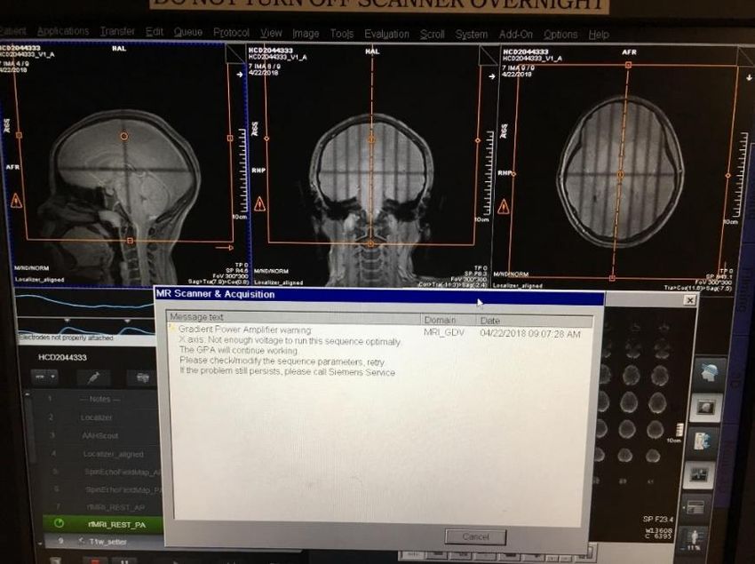
Revision Date: 9/23/2021
•
Adjustment Measurement Was Aborted ............................................................... 26
•
Gradient Power Amplifier Warning...................................................................... 26
•
Participant Registration Errors .............................................................................. 27
Slice Timing for BOLD Sequences and other BOLD Questions ............................................ 28
Preparation Scans related to Regular BOLD Sequences ........................................................ 29
Current Designs Button Box and Trigger Setup (FORP 932) ................................................ 30
• Device Selection ................................................................................................... 30
• Response Settings ................................................................................................. 30
• Troubleshooting .................................................................................................... 31
Goggle Setup ................................................................................................................................ 33
• Tech Remote (Talk Box) ...................................................................................... 33
• Visuastim Controller ............................................................................................. 33
• Troubleshooting .................................................................................................... 34
Resonance Technology Tech Remote (Talk Box) Setup .......................................................... 35
• Volume Settings .................................................................................................... 35
• Audio Input ........................................................................................................... 35
• Comm. Mode settings ........................................................................................... 35
• Tech Remote Reset ............................................................................................... 36
Siemens Talk Box Setup ............................................................................................................. 37
Optoacoustics Headphone and Microphone Setup .................................................................. 38
• Positioning the Participant .................................................................................... 38
• Setting up the Opto Console ................................................................................. 38
• Using Active Noise Cancellation .......................................................................... 39
• Troubleshooting Tips ............................................................................................ 40
BOLDScreen LCD ...................................................................................................................... 41
• Specifications ........................................................................................................ 41
• Turning on the LCD .............................................................................................. 41
• Positioning the Participant .................................................................................... 41
• Troubleshooting Tips ............................................................................................ 42
How to use E-Prime with the Desktop Computer and LCD ................................................... 43
• Duplicate/Mirrored Display with E-Prime............................................................ 43
• Extended Display with E-Prime............................................................................ 43
• Switching from Extended Display to Duplicate/Mirrored Display ...................... 43
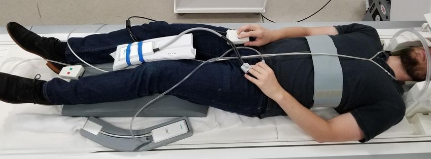
HCP Physiological Device Setup................................................................................................ 44
• ECG/Respiratory Setup ......................................................................................... 44
• Pulse Setup ............................................................................................................ 44
How to Use FIRMM to Monitor Motion during BOLD scans................................................ 45
• Quick Overview .................................................................................................... 45
• Setup the Scanner Console.................................................................................... 45
• Setup the Computer to View FIRMM .................................................................. 45
• Using FIRMM ....................................................................................................... 46
• HCP Guidelines (see full HCP SOP for more details) .......................................... 47
• After the Scan is Complete ................................................................................... 47
How to Use the MR Camera ...................................................................................................... 48
• Quick Overview .................................................................................................... 48
• Equipment ............................................................................................................. 48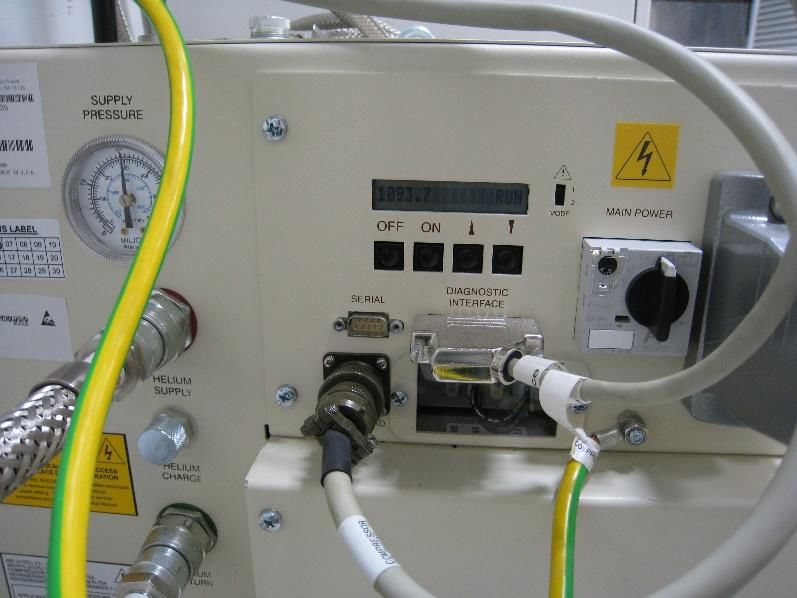
Revision Date: 9/23/2021

                •
                Camera Setup ........................................................................................................ 48
                •
                Participant Setup ................................................................................................... 49
                •
                Camera Cleanup .................................................................................................... 49
                •
                Troubleshooting Tips ............................................................................................ 49
Equipment Manuals.................................................................................................................... 50
          • Current Designs Button Box and Trigger Manual - Forp 932 .............................. 50
          • ViewPoint Eyetracker User Guide* ...................................................................... 50
          • ViewPoint Eyetracker Data Analysis Guide* ....................................................... 50
          • Optoacoustics Manual ........................................................................................... 50
          • MRI Safety Manual............................................................................................... 50
Movie List .................................................................................................................................... 51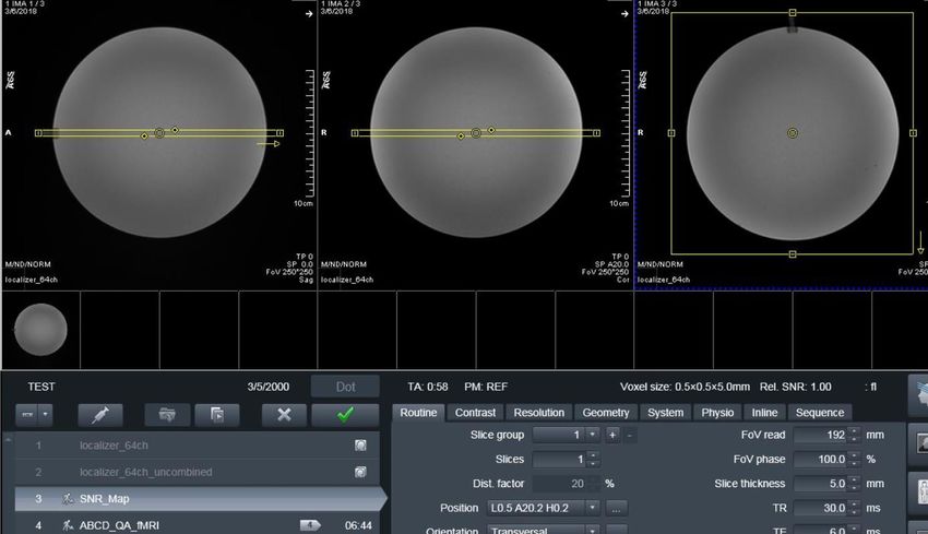
Revision Date: 9/23/2021

                            BMC Contacts

1.   Ludmila Budilo   Building Manager                 x52699
2.   Mary Susselman   PET/MRI Tech                     x64291
3.   Trent Thixton    Lead MRI Tech                    x59217
4.   Darin Williams   Engineer                         x64291
5.   Dr. Roger Woods  Center Director                  x44057
6.   BMC Techs        BMCTechs@mednet.ucla.edu         (424) 652-6290
7.   BMC Emergency ONLY Line: 323-999-1593

     1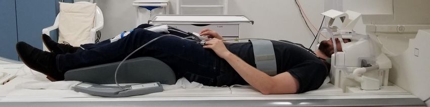
Revision Date: 9/23/2021

                                     Scanner Operation

How to do a “Standby” Reboot
This type of reboot clears most errors and takes approximately 10 minutes

   1.   Make sure the scanner bed is at the home position (all the way up and all the way out)
   2.   If a coil is on the table, all element should be plugged in
   3.   Click the “System” tab at the top of the screen
   4.   Click on “Control”

   5. Click the “Meas & Recon” Tab
   6. Click “Standby”

   7. Click “Yes” to the pop up message if needed

   8. The system will take 1-2 minutes to turn off – you will hear a “clunk” when the
      equipment shutdowns and the LCD screen in the scanner room will turn off

        2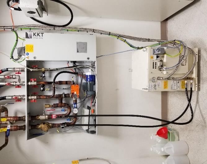
Revision Date: 9/23/2021

   9. Wait a few seconds and then press the “system on” button on the Siemens scanner control
      box located on the wall next to the MR Scanner window

   10. When the scanner starts booting up, the LCD screen in the scanner room will turn back
       on
   11. It will take approximately 6 minutes for the system to completely boot up

How to Turn Off the MRI Scanner/Computer (Full Shutdown)
This type of full shutdown takes approximately 20 minutes – try this method if a “Standby”
reboot did clear the issue

   1.   Make sure the scanner bed is at the home position (all the way up and all the way out)
   2.   If a coil is on the table, all element should be plugged in
   3.   Click the “System” tab at the top of the screen
   4.    Click on “End Session”

   5. Click “Shutdown System”

   6. It will take approximately 5 minutes before you see “it is now safe to turn off your
      computer”

        3
Revision Date: 9/23/2021

   7. Press the blue “system off” button on the Siemens scanner control box located on the
      wall next to the MR Scanner window

How to Turn on the MRI Scanner/Computer
   1. You must first press the “system on” button on the Siemens scanner control box located
      on the wall next to the MR Scanner window

   2. It will take approximately 15 minutes for the system to completely boot up
   3. After a successful reboot you will hear 3 beeps

MR Scanner Error Save Log
   1. If you ever have a scanner problem that requires you to reboot, it is very important to
      make a MR Save Log entry BEFORE you reboot the system
   2. This log entry helps the Siemens engineer isolate the scanner problem and expedite the
      system repair. To make a MR Save Log entry, you must do the following:
          • At the top of the screen – click system, then control, then tools
          • Click on “Save system log files”
                   o You will see a box pop up with script on a black background, LEAVE
                       THIS ALONE!
                   o Another box will pop up where you can input the problem
                   o Fill out the “User” section and then click OK
                   o You must wait until the black pop box with script closes before you can
                       proceed to reboot, scan etc
   3. Please email BMCTechs@mednet.ucla.edu with details of the problem

      4
Revision Date: 9/23/2021

How to Check the System Manager
   1. Click the “System” tab at the top of the screen
   2. Click on “Control”

   3. You will get a “System Manager” pop-up box - within the “System Manager” box you
      can check that the “Host,” “Meas & Recon ” and “Periphery” components are working
      properly

      5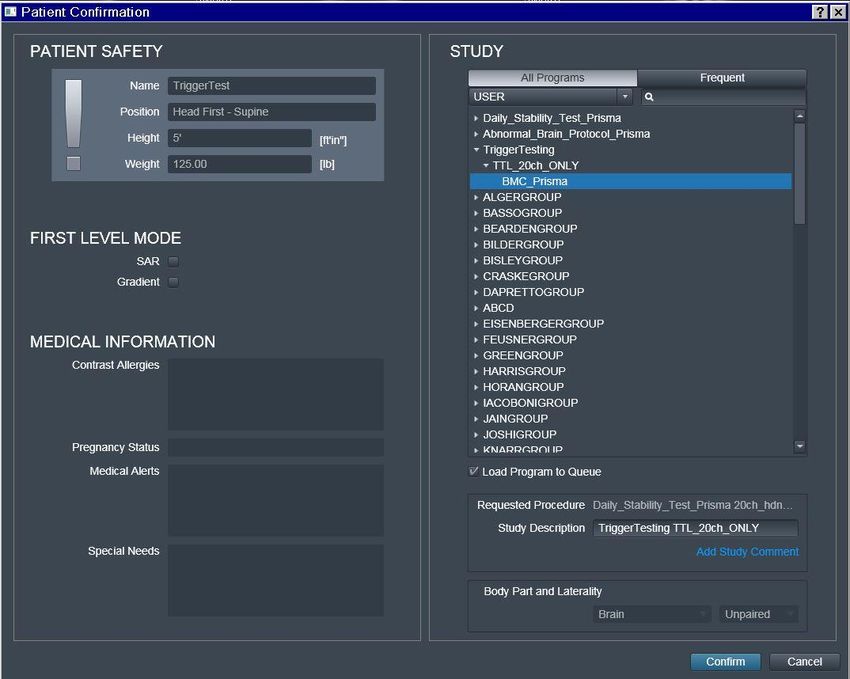
Revision Date: 9/23/2021

How to Restart the Coldhead
   1. In case of a power-surge, or other problem, the Coldhead may need to be restarted
   2. You will know the Coldhead has been shut off if you do NOT hear the steady “chirping”
      noise in the scanner room
   3. Enter the equipment room (through the sliding glass door) and look at the south wall (as
      shown below)

   4. The coldhead is the white “box” next to the large cabinet
   5. Walk over and look at the front of the coldhead and you will see the Coldhead controls
      (shown above)
   6. Press the ON button and the Coldhead should turn back on
   7. Please be sure to notify BMCTechs@mednet.ucla.edu and/or Dr. Woods if this occurs

      6
Revision Date: 9/23/2021
How to Reboot the Chiller
1. If you get “cooling errors” while scanning you can try to reboot the chiller to clear the
faults, some examples include:
• Cooling System: EPC Temperature High
• Cooling System: Return Pressure Low
• Cooling bypass
2. Enter the equipment room (through the sliding glass door) and look at the south wall (as
shown below)
3. Locate the key to the chiller cabinet on the ledge (red circle)
4. Unlock the cabinet (green circles)
1
2
3
5. Turn off the 3 breakers in the chiller cabinet (orange squares), wait 5 seconds and then
turn them back on
6. Then do a “Standby” scanner reboot (not a restart or full shutdown) – this takes 10
minutes
7. Please be sure to notify BMCTechs@mednet.ucla.edu and/or Dr. Woods if this occurs
7Revision Date: 9/23/2021
Re-import DICOM Data
How to Map a Dicom Network Folder on the Scanner Console
1. Click control and click escape key
2. Click Advanced User and input password if not already logged in (contact techs for the
password)
3. Click control and click escape key
4. Click Computer
5. Disconnect any other network drives that may still be mapped – right click on the drive
and choose disconnect
6. Click on “Map Network Drive” on the top tool bar
7. When the box pops up choose an available drive, Z drive is the default, if it is being used
choose the next available letter (i.e. Y, X, W etc) – DO NOT use drive M
8. Under “Folder” choose the path \\10.2.0.98\DICOM7 (or whichever dicom you are trying
to access dicom7 is the current data directory)
9. Click on “Connect using different credentials" then click finish
10. Log in with your NRB credentials (don't forget the \bmap) before your name
• bmap\username
• Password
11. Navigate to your group folder and choose the participant folder that you want to import
12. Right click on the folder and click Copy
13. Now, open up Computer – then, Med System C: Temp/_User_Data (select a temp folder
or create a new one)
14. Paste the copied files into the Temp folder
15. Now go to the Patient Browser – Transfer – Import from Off Line
16. A box pops up for you to browse the Temp folder
17. Select your Temp folder (i.e. C: Temp/User_Data/Woods)
18. Select scan folder that you want to import
19. This loads the images/sequence to the patient browser
20. You can now export raw data or import sequences into your exam card
21. When you are done, go to Computer right click on the drive you mapped and click
disconnect - this will log you out
8Revision Date: 9/23/2021
Export and Save Raw Data Files (.RDA and Raw)
How to Map a Non-Dicom Network Folder on the Scanner Console
1. Click control and click escape key
2. Click Advanced User and input password if not already logged in (contact techs for the
password)
3. Click control and click escape key
4. Click Computer
5. Disconnect any other MRIFILE drives that may still be mapped – right click on the drive
and choose disconnect
6. Click on “Map Network Drive” on the top tool bar
7. When the box pops up choose an available drive, Z drive is the default, if it is being used
choose the next available letter (i.e. Y, X, W etc) – DO NOT use drive M
8. Under “Folder” choose the path \\10.2.0.98\ MRIFILE or enter the path name manually if
this is your first time mapping the drive
9. Choose your group folder
10. This drive will allow you to save raw data etc into the network folder instead of on a usb
drive
11. Click on “Connect using different credentials" then click finish
12. Log in with your NRB credentials (don't forget the \bmap) before your name
• bmap\username
• Password
13. When you are done close the non-dicom folder windows
14. Right click on the drive you mapped and click disconnect - this will log you out
15. If your non-dicom NRB account is not working – save the raw data on the C: Drive in
Temp/YourName/SubjectID folder
16. Note – please remember to periodically delete saved data from your non-dicom folder
and scanner console temp folder – data is not meant to stay in these folders indefinitely as
there is limited space
How to Create a Spectroscopy .RDA File
1. Enable the advanced user mode (contact techs for the password)
2. Click control and click escape key
3. Pull the scan back from the server if necessary
4. Go to the spectroscopy tab
5. Click the file browser
6. Load the spectrum of interest in the spectroscopy tab
7. Then click on the spectrum you want to create an .rda file for
8. Click options on the tool bar
9. Then click export raw data
10. Copy and paste these files into a temp folder on the C drive - typically your group will
have their own temp folder
11. You can then move/copy it to a flash drive or a non-dicom folder
12. This data does not get over written as long as you have the scan data
9Revision Date: 9/23/2021
13. Data needs to be manually deleted from the temp folder and non-dicom folder
How to Transfer Raw Data Using TWIX Software
1. Enable the advanced user mode (you will need a tech for this step)
2. Click control and click escape key
3. Open the command terminal
4. Type: TWIX - then press enter
5. All raw data will be listed
6. Select the raw data you wish to save by choosing the correct participant ID and sequence
7. Right click on it and choose the top option "copy total raid file"
8. Copy and paste these files into a temp folder on the C drive - typically your group will
have their own temp folder
9. These files can then be copied to a non-dicom folder or flash drive
10. Data needs to be manually deleted from the temp folder and non-dicom folder
10Revision Date: 9/23/2021
How to Burn a CD From The Scanner Console
1. Open the second disc drive on the scanner desktop computer and insert a blank DVD or
CD (must be –R)
2. Open the patient browser on the console once the blank CD has loaded (takes about
30sec)
3. Highlight the participant's parent level folder for the whole scan or any individual
sequences you want to burn (use CTRL to highlight multiple seq at once)
4. Click Transfer and then Export to… (if Export is grayed out the CD hasn't loaded yet)
5. Choose DVD-R then click Export
6. Name the CD and make sure the viewing tool check box is checked
7. Click OK
8. When it is done click Transfer at the top of the patient browser and Eject DVD-R
11Revision Date: 9/23/2021
Prisma Cleanup Procedures
General Cleanup Guidelines
1. Put the head coil away in the coil cabinet with top attached
2. All cables should be untangled and placed on the appropriate hooks completely off the
ground to prevent being stepped on (please see below pictures)
3. All equipment (goggles, headphones, button box, squeeze ball/button etc) that you used
should be wiped down with alcohol wipes for cleanliness
4. The button response box should be disconnected and store in the appropriately labelled
drawer - the button response box sleeve should be removed if used
5. The squeeze ball should be coiled at the end of the bed
6. One sandbag should be left on the white cart
7. The Opto box should be turned off at back of box
8. The Opto audio cable should be unattached from audio source and coiled up in the
drawer
9. The trigger, LCD HMDI, goggle VGA and EPI cables should be coiled and stored
10. The Res Tech system should be turned to “Off” under “System” – you do not need to turn
off the “Visor”
11. The LCD switch box should be turned off
12. The goggles, EXT and EPI buttons should be turned off on the desktop switch box
13. Everything is labelled for your convenience
14. Note: the top of the cart is now a suitable place to set the top of the coil and/or mirror
when you are setting up your participant
12Revision Date: 9/23/2021
Squeeze Ball/Button Alarm
What to do when the Squeeze Ball/Button Alarm Goes Off
1. Stop the scanner using the mouse and clicking the stop icon in the lower left on the
console screen
2. To clear the alarm, press the talk button on the intercom associated with the squeeze ball
- Siemens (#2 talk or #3 alarm) or headphones button - Res Tech (TALK) you gave the
participant
3. Talk to your participant through the intercom system associated with the headphones you
gave your participant (res tech, siemens or opto system)
4. DO NOT press the “Stop” button (#1) on the Siemens Talk Box
5. If you press this, you will need to reset the table
6. To reset the table follow the below instructions
Reset the Table
1. Press the (#7) button on the side of the intercom box
2. Go into the scanner room and simultaneously press the Table Up and Table Down button
13Revision Date: 9/23/2021
How to Run the Daily Stability Warmup
Setting up the Phantom
1. Place the phantom and phantom cushion inside the either the 20, 32 or 64 channel head
coil (round end at top of coil)
2. Secure the top half of the head coil by clicking it in and plugging in cable(s) if necessary
3. Raise the table
7. Turn on the laser light and set the landmark
8. Slide the table fully into the scanner
9. Close and flip the air seal on the scanner door
Register Phantom
1. Press the “little person” key on the keyboard to bring up the registration screen
2. Enter phantom information (all required fields are indicated in bold except required data
destination= Referring physician)
• Last Name = enter information in the following format – Stability-date-of-
scan_name-of-scanner.
• e.g. “Stability082609_Prisma”
• Patient ID = copy the information from the Last Name field to the Patient ID
field.
• Sex = “other”
• Age = “18”
• Height = “5ft”
• Weight = “125 lbs”
• Referring Physician = select “QC Group”
• Patient Position = select “Head First Supine”
3. Click “Exam”
4. Another box will pop up
• Choose Study = Daily_Stability_Test _Prisma
• Choose stability sequence based on the head coil you used (BMC_20ch,
BMC_32ch or BMC_64ch etc)
• Click “Confirm”
Running Scans
1. Press the green play button to start the first localizer
2. First stability sequence will open itself – center the box on the phantom and then click
“the green check”
3. The other stability sequences will automatically copy the slice locations from the first
stability sequence and will automatically start (you will not need to click continue)
4. When scanning is complete, remove the phantom/holder and place them securely in the
phantom cabinet bin
14Revision Date: 9/23/2021
Registration Pictures
15Revision Date: 9/23/2021
How to Run the ABCD Phantom QA
The ABCD phantom should be run at least once per week. This QA protocol may take
the place of the daily warmup. The full version takes 29min and the quick version takes
16min.
Setting up the Phantom
1. Place the spherical ABCD phantom inside 32 (ABCD/HCP protocols) or 64 (Other) head
coil on top of the white cushion
2. Place the gray cushion in front to secure the phantom (32ch coil only)
3. Cushions are located next to the phantom in the bin
4. The cap of the phantom should be center as if it were the nose – it should line up with the
laser landmark line on the coil
5. Secure the top half of the head coil by clicking it in and plugging in cable(s) if necessary
6. Raise the table
7. Turn on the laser light and set the landmark to run through the cap
8. Slide the table fully into the scanner
9. Close and flip the air seal on the scanner door
32 Ch Coil
64 CH Coil
16Revision Date: 9/23/2021
Register the Phantom
1. Press the “little person” key on the keyboard to bring up the registration screen
2. Enter phantom information (all required fields are indicated in bold except required data
destination= Referring physician)
• Last Name = ABCDPhantom017_32CH or ABCDPhantom017_64CH
• Patient ID = copy the information from the Last Name field to the Patient ID
field.
• Sex = “other”
• Age = “18”
• Height = “5ft”
• Weight = “100 lbs”
• Referring Physician = select “ABCDPHANTOMGROUP”
• Patient Position = select “Head First Supine”
3. Click “Exam”
4. Another box will pop up
• Under ABCD choose the appropriate protocol:
o ABCD_QA_full__32ch (29:04min)
o ABCD_QA_quick__32ch (15:36min)
o ABCD_QA_full__64ch (29:04min)
o ABCD_QA_quick__64ch (15:36min)
• Click “Confirm”
17Revision Date: 9/23/2021
Running Scans
1. Press the green play button to start the first localizer
2. Set up sequence #3: SNR_Map by centering the yellow box on the phantom – it should
be placed right through the cap (the cap is circled in red below) then click the green
check (green circle)
3. Set up sequence #4 by centering the yellow box on the phantom – click the green check
4. Press ok to the “Stimulation Monitor Warning” that will pop up after #3 finishes running
– you can step away to let the sequences auto run after this step
5. The rest of the sequences will automatically copy the slice locations from #4 and run
automatically
6. When scanning is complete, remove the phantom/cushions and place them securely in the
phantom cabinet bin
18Revision Date: 9/23/2021
Registration Pictures
19Revision Date: 9/23/2021
How to Trigger Test Stimuli/Tasks
Setting up the Phantom
1. Place the phantom and phantom cushion inside the 20ch head coil (round end at top of
coil)
2. Secure the top half of the head coil by clicking it in and plugging in cable(s) if necessary
3. Raise the table
10. Turn on the laser light and set the landmark
11. Slide the table fully into the scanner
12. Close and flip the air seal on the scanner door
Register Phantom
1. Press the “little person” key on the keyboard to bring up the registration screen
2. Enter phantom information (all required fields are indicated in bold except required data
destination= Referring physician)
• Last Name = TriggerTest
• Patient ID = copy the information from the Last Name field to the Patient ID
field.
• Sex = “other”
• Age = “18”
• Height = “5ft”
• Weight = “125 lbs”
• Referring Physician = select “QC Group”
• Patient Position = select “Head First Supine”
3. Click “Exam”
4. Another box will pop up
• Choose Study = TriggerTest
• Click “Confirm”
Running Scans
1. Double check the sequence to open and then click the “the green check” to start the shim
2. When you are ready to trigger your task please the continue button
3. Don’t forget to plug the trigger cable into your computer
4. When scanning is complete, remove the phantom and place it securely in the phantom
cabin
20Revision Date: 9/23/2021
Registration Pictures
21Revision Date: 9/23/2021
Coil Warnings - Protocol Was Fixed
If you see warning messages while scanning, please read the message and address the
issue. DO NOT just click “OK”. Ask a tech for help if you are uncomfortable with
resolving the issue on your own. Please be vigilant, as we do not refund scans for this
type of issue.
Main Reasons for Coil Warnings
1. The coil wasn’t plugged at all or properly
2. The subject was registered and the protocol was loaded into the exam card before
plugging in the coil
Anterior (HEA)
Anterior or Posterior Protocol Fixed Warning Messages
portion of 32ch
1. The pop up message will let you know that it is turning off coil not active
the elements that are not plugged in properly
2. If you click “OK”, you will be approving this change and
you will lose signal from that part of the coil
3. Data collected in the manner will be suboptimal and most
likely unusable
Resolution
1. Check the coil plugs Anterior (HC1,3,5,)
2. Reseat the plug if necessary portion of 64ch coil
3. Make sure the LCD screen displays the anterior and not active
posterior elements
4. Close your subject
5. Re-register the subject
6. Try again
Wrong Coil Protocol Fixed Warning Messages
1. The wrong coil was put on the scanner bed Coil changed
from 64ch to
• The message will let you know that it is changing
32ch
the coil to the one you put on the scanner bed
• Your data is not be “bad” per se, but you won’t be
using the proper coil for your study
• Resolution: change the coil, close and re-register
your subject
2. The protocol was not setup for the correct coil
• The message will let you know that it is changing
the coil to the one you put on the scanner bed
• Resolution: this is the only scenario where it is ok to click “OK” and proceed
• Let a technologist know that your protocol is setup with the wrong coil so it can
be fixed
22Revision Date: 9/23/2021
• Check which coils are turned on in the system card of the sequence after the
system auto detects the new coil to make sure they are correct
• Note – if you are using the 20ch or 64ch coils the neck elements “NE” do not
need to be on
23Revision Date: 9/23/2021
Prisma VE11C Software Bugs
This is a list of known software bugs/glitches. If you encounter any other suspected issues,
please report them to bmctechs@mednet.ucla.edu and/or during study reporting.
AutoAlign Re-Run Failure
This glitch ONLY happens if you run a second autoalign or localizer scout. For example, if the
subject had to come out to use the restroom or needed to be re-positioned. If you require an
additional localizer for any reason, you MUST check all subsequent scans to make sure the
autoalign angle is properly applied. If you do not use autoalign then this does not affect you.
Workaround:
1. Open each subsequent scan after the new autoalign localizer has been run and then click
the green check mark to apply autoalign
2. When you open the sequence you should see the yellow FOV adjust
3. Some sequences do not have a “working man” symbol on the left side, so they will
not automatically open to be applied
4. Please be vigilant in opening all subsequent sequences and/or add the working man after
rerunning the new localizer so they will automatically open and require application
5. For those of you who have scheduled breaks built into to your study we highly
recommend that you turn on or make sure the working man is turned on for all post break
sequences
6. The below linked SOP was made specifically for the HCP study, but it will give you an
idea of what to look for
• AutoAlign Glitch SOP
***This glitch has been reported to Siemens, but they have informed us that it will not be
fixed in this software version
AP/PA Copy Reference Issue
If you are using Siemens product sequences with different phase encoding directions (e.g. AP
then PA), you MUST NOT use the copy reference option. This glitch will change your second
PA sequence to RL. This glitch does not affect CMRR, HCP or ABCD sequences as the phase
encoding direction is controlled on the special card instead of the routine parameter card.
Workaround:
1. You must manually input the angle for each sequence if you are manually prescribing
your FOV
2. If you use autoalign and DO NOT manually adjust your FOV in any way then your scans
will not be affected and there would be no need to use copy reference
***This glitch has been reported to Siemens, but there is no way to know when and if
there will be a fix.
24Revision Date: 9/23/2021
Reconstruction Error (aka Blob error)
This intermittent issue causes the data to not reconstruct. The scanner will acquire the data and it
will even show up in the inline display, but it does not create the reconstructed saved images.
Workaround:
1. The only way to confirm that the data has reconstructed is to review your data in the
browser
2. If it populates in the browser then it should be ok, however, as good general practice we
also recommend pulling it into the viewer to QA each sequence
3. This glitch has only happened 3 times so far at BMC, but it has happened at many other
prisma sites as well, so please be sure to check your data as you are acquiring
4. If this error does occur, you must stop scanning and do a standby shutdown on the
scanner to fix the glitch
5. Note, this will not recover the data so it is important to check each sequence as you go
***This glitch has been reported to Siemens, but there is no way to know when and if
there will be a fix. This issue has not occurred since Dec 2017.
25Revision Date: 9/23/2021
Prisma VE11C Scanner Warnings/Messages/Errors
Adjustment Measurement Was Aborted
If you ever encounter any kind of adjustment error try to see if the scanner will let you continue
scanning by clicking ok on the error and re-running the sequence. If you can’t continue then
perform a standby shutdown which takes about 5-7 min. Some examples are show below.
Please submit the issue as an equipment failure during study reporting.
Gradient Power Amplifier Warning
If you ever seen the below warning/orange FOV box,
1. Check your first localizer to ensure the subject’s brain is positioned correctly at isocenter
– the cross hair should be center in the brain in the head to foot direction (see below pic)
2. If it is, then it is safe to continue scanning as is, but please alert
bmctechs@mednet.ucla.edu
3. If it is not, stop scanning, re-laser your subject to their eyebrows, close the patient, re-
register and start again
26Revision Date: 9/23/2021
Participant Registration Errors
1. You cannot confirm your registration due to the below error
• This happens when there are still active sequences in the Exam Card
• Go back to the Exam card and stop (red square) or Skip (>) the remaining
sequences in the queue
• This happens when a participant aborts a scan early or the group runs out of time
and stops scanning before their protocol is complete
• Also note, you will not be able to close the patient on the Exam card until the
sequences are stopped, skipped and/or deleted
2. The registration exam button is grayed out so you cannot click it
• This means you have forgotten to complete a required field
• Required fields are in bold
• NOTE: “Date of Birth” is bold, but we use “Age” instead – please do not input a
DOB – once you input the age a general DOB will be generated
• NOTE: Referring Physician is not bold but is required to access your data
27Revision Date: 9/23/2021
Slice Timing for BOLD Sequences and other BOLD Questions
1. When EPI slice are collected in a mosaic/volume, are they interleaved or sequential?
• Interleaved (that is the default)
2. When collected interleaved, are all the odd numbered slices collected first?
• It depends on the number of slices in the group
• If there are an even # of slices then even numbered slices are collected first
• If there are an odd # of slices then odd numbered slices are collected first
3. Is slice #1 always at the “lowest” part of the brain and the last slice at the top?
• The default “image numbering” in the transversal/axial plane is F>H - so the
bottom slice is acquired first
4. In regards to the timing of slices, is the scanner set to collect slices in an equidistant
fashion within the TR time or as fast as possible?
• Within the TR time
28Revision Date: 9/23/2021
Preparation Scans related to Regular BOLD Sequences
1. To ensure that a steady-state magnetization is achieved when multiple averages or
measurements are acquired, a number of preparation scans are performed at the start of
the measurement
2. The number of preparation scans is set within the sequences, and chosen so that the
preparation time is longer than 3 seconds
• TR = 500 ms 7 preparation scans
• TR > 501 ms 6 preparation scans
• TR > 601 ms 5 preparation scans
• TR > 751 ms 4 preparation scans
• TR > 1001 ms 3 preparation scans
• TR > 1501 ms 2 preparation scans
• TR = 2000 ms 2 preparation scans
• TR = 2500 ms 2 preparation scans
• TR = 3000 ms 2 preparation scans
• TR > 3001 ms 1 preparation scan
3. The preparation scans result in a longer scan time for the first measurement in a time-
series acquisition, which should be taken into account when performing BOLD imaging
4. The sequence does not send external trigger pulses when performing these preparation
scans, so that they do not have to be considered when triggering external devices for
stimulus presentation in BOLD imaging studies
5. This formula does not apply to multiband bold sequences
6. Turning iPAT on will add 1 additional prep scan
7. Turning introduction “on” will add 1 additional prep scan
29Revision Date: 9/23/2021
Current Designs Button Box and Trigger Setup (FORP 932)
There is no on/off switch and this device does not need to be unplugged
Device Selection
1. DO NOT set the interface settings until you plug in the button box inside the scanner
room – the button responses will not work
2. Note - you do not need to plug in a box if you only need a trigger – just choose your
interface setting with appropriate trigger (5s or Ts)
3. Click dial in once and scroll to yes in “change modes” menu and click dial once
4. Scroll to “autoconfigure” and click dial once
5. Scroll to “usb” and click dial once
6. Below is a list of available devices – autoconfigure will automatically choose the box that
is connected in the scanner room
• HHSC - 1X4-L - buttons straight in a row
• HHSC - 2X2 - split boxes, you may use just one box if applicable
o Left box sends dnwe or 9876
o Right box sends bygr or 1234
• HHSC – 2x4 - curved row of buttons, you may use just one box if applicable
• HHSC Joy-1 joystick (older model than what is on the current designs website)
• HHSC TRK-1 trackball
7. You may see other devices listed that are not available, contact BMC Techs for more info
8. Once you have selected your device, you will see the “Response Settings” menu
Response Settings
1. Scroll to applicable setting and click dial once
2. "KEY" sends the button press signal as soon as the button is pressed but stops sending
the button press signal immediately after sending it once
1. HID KEY BYGRT - use this for letter responses and T is the trigger
o this is the same as 0 setting on previous interface box
2. HID KEY 12345 - use this for number responses and 5 is the trigger
o this is the same as 4 setting on previous interface box
3. "NAR" sends the button press signal as soon as the button is pressed but keeps sending
the button press signal until the button is physically released
1. HID KEY NAR BYGRT - use this for letter responses and T is the trigger
o this is the same as 2 setting on previous interface box
o this setting is often required for psycho tool box in matlab
2. HID KEY NAR 12345 - use this for number responses and 5 is the trigger
4. HID KEY 1-9 No 5 - for MacStim users: no trigger will be sent, must manually start scan
30Revision Date: 9/23/2021
5. On the small screen you will see the “setting description” which includes
the device selected as well as the response setting selected
6. Be sure to plug in the trigger cable before starting your stimuli
7. Set the interface back to the “autoconfigure” menu after scan
Troubleshooting
Button Response and Trigger Interface Box
Response Lights
1 2 3 4 5 Trigger Light
BYGRT
A. Button responses are not coming through
1. If the button response lights (red circle above) on the interface are visible, but your
computer is not receiving the responses then
• Check to make sure the trigger cable is plugged into your computer
• Check to make sure you have chosen the correct response setting (12345 or bygrt)
2. If the button response lights (red circle above) are not visible on the interface
• Check to make sure the correct button box is plugged in inside the scanner room
• Make sure your participant is pressing the buttons
B. The task is not triggering
1. Make sure the trigger cable is plugged in to your computer
2. Make sure the interface is set to the appropriate trigger value in your script (5 or T)
3. Make sure you started the scan and waited long enough for the dummy time to complete–
the trigger light (green square above) on the interface will blink once triggers are being
sent so you can watch for the signal
4. Make sure you are on the correct screen on your computer for the task to begin
(sometimes you may need to advance to another screen)
5. Check your script
6. Check the trigger cable connection on the interface box to
make sure it is secure
• the blue circle on the below picture shows where it
connects in the back of the interface box – it does
not lock in place or screw in, so just push on it
gently to make sure it is seated on the connector
• the yellow square is the other end of the
connection – this should not come loose as it screws in, but you can also check it
to make sure it is connected
• BE VERY careful not to unscrew/loosen anything else – DO NOT remove box
from velcro
31Revision Date: 9/23/2021
C. USB is flashing on the interface LCD screen
1. This indicates the USB trigger cable is not plugged into your computer
D. It looks like buttons are being held down because the button interface lights are on
1. Check the interface settings first – it is likely that the interface is set for the wrong box
(i.e. 2x2 instead of 1x4 etc)
2. Ask the participant if they are pressing/holding down the buttons
3. Check the actual button box to see if something is pressing against the buttons
E. Interface Menu Issues
1. If you get “lost” in the menu, just scroll down to “back” until you get to the proper menu
32Revision Date: 9/23/2021
Goggle Setup
Tech Remote (Talk Box)
1. To change any settings on the Tech Remote intercom you will need to scroll the far right
wheel “Menu” to the appropriate setting - press down on the wheel - scroll to change the
setting - press down again to lock in that setting
2. Connect the goggle VGA cable to the laptop or select “GOGGLES” on the “desktop
switch box” if you are using the desktop computer
3. Connect the appropriate audio cable (res tech or opto) to the computer you will be using
• Laptop: the audio cable connects directly to the laptop
• Desktop: the res tech audio cable connects to the audio jack in the white drawer
labelled “AUDIO TO DESKTOP”
4. Make sure the computer is on (BMC Mac laptop, your laptop or the Dell Desktop)
5. Go to Menu on the “Tech Remote,” and set the “Video Mode” (what the participant sees)
If you want the participant to see If you want the participant to see
the laptop the Dell Desktop
6. Go to Menu on the Tech Remote and turn on the “System PWR” (turn this off when you
are done with your scan)
7. “Visor PWR” should always be on (do not turn off after scan)
Red Light Blue Light
8. DO NOT assume that the display on the “Goggles” monitor will be correctly mirrored to
the goggles – always verify the correct display is being projected by physically looking
through the goggles during protocol development scans or by asking the participant to
describe what they see on the screen
Visuastim Controller
1. On the “Visuastim Controller,” make sure the “Monitor Input” (what the researcher sees
on the “Goggles” monitor) is set to:
33Revision Date: 9/23/2021
• RIGHT if you want to see the Dell Desktop on the “Goggles” monitor
• LEFT if you want to see the BMC Mac laptop or your laptop on the “Goggles”
monitor
Troubleshooting
1. If the goggles aren’t working, turn off the “System PWR” on the talk box, wait 10
seconds and then turn it back on
2. If the goggles still aren’t working
• Check the VGA cable if using a laptop
• Check the “Tech Remote” to make sure
o “VISOR PWR” is on
o “System PWR” is on
o MONO-L or MONO-R has been appropriately chosen
o “VideoRES” is set to 60Hz, 800x600
• Make sure the appropriate monitor input is chosen on the “Visuastim Controller”
box – this only controls what you see on the monitor not what the
participant sees on the goggles screen
• Check to make sure the computer’s resolution is set to 800x600 at
60hz
• Make sure the goggle power supply is turned on
o Check the black box to the left of the BMC Mac laptop –
the switch is in the front – green light on top
• Make sure that the “Visuastim Controller” is turned on (red circle
below)
3. If the goggles still aren’t working, try the 1-2-3 tech remote reset
34Revision Date: 9/23/2021
Resonance Technology Tech Remote (Talk Box) Setup
Volume Settings
1. Hearing sensitivity varies so always check with your participant to make sure you are
using the appropriate volume level - start at a level of 50 and adjust up or down from
as needed
2. Patient Volume (wheel #1): Changes the volume in the participant’s headphones -
what the participant hears task or movie computer
3. Patient Mic (wheel #2): Changes the volume of the participant’s voice – what the
operator hears when the participant talks
4. Main Volume (wheel #3): Changes the volume of the control room speaker which
outputs sound from the operator’s computer (i.e. tasks, music or movie) – so you can
hear what the participant hears
5. To change the operator’s volume - what the participant hears from the researcher –
hold down the talk button and scroll wheel #1
Audio Input
1. Should be set on “Audio-1”
2. Click “Menu” then scroll to “Audio Input”
3. If you are plugging in an external audio device to the interface speaker (i.e. ipod) you
must change to "Audio-2"
Comm. Mode settings
1. Click “Menu” then scroll to “Comm. Mode”
2. The "manual" setting automatically turns off the sound coming from the participant's mic
after a few seconds
3. The "auto" setting will have constant sound coming from the mic – (i.e. you will be able
to hear scanner noise - not ideal to use this setting while scanning)
35Revision Date: 9/23/2021
Tech Remote Reset
1. Scroll first blue wheel to 1
2. Scroll second blue wheel to 2
3. Scroll third blue wheel to 3
4. Hold down the TALK button until you see it countdown 15 seconds
5. You will see the box initializing and then read: Transducer Off
6. You may now adjust the system according to your specifications
7. You will also see the screen’s default appearance as above
36Revision Date: 9/23/2021
Siemens Talk Box Setup
1. You must use the Siemens talk box to talk & listen to your participant if you are using the
Siemens headphones or no headphones
2. You must also make sure that the volume on the scanner’s control panel is turned up so
the participant can hear the task computer
3. Press the “ear” button (#4) to hear the participant
4. This is the sound that comes from bore speaker - you can use this to listen even if you use
the res tech or opto headphones
5. Make sure the sound is turned up
6. Press the “talk” button (#2) to talk to the participant
7. Make sure the sound is turned up
8. For music plug in audio device to the port labelled (#6)
37Revision Date: 9/23/2021
Optoacoustics Headphone and Microphone Setup
Positioning the Participant
1. You may use the Opto headphones with or without earplugs
2. Position the headphones on the participant and be sure to use pads or paper towels to take
up the extra space between the headphones and coil (this is especially important if you
are using the active noise cancellation feature)
3. Position the microphone if applicable - be sure it is almost touching the participant’s lips
Setting up the Opto Console
1. AFTER moving the participant into the bore, turn on the Opto control box
using the black switch on the back right side of the console
2. Touch the screen to continue
3. If you are playing audio (movie, music or an audio task) connect the audio
cable to either the green connection inside the white drawer for the desktop
computer or to a laptop port – the other end of this should be connected at the
back of the Opto console in “line 1”
4. The line 1 (#5) knob controls the volume of this audio
5. The left button (#4 FORMI NOISE CANCELLER) on the Opto console should always
be pressed down “On”
6. The right button (#3) should always be up (in the FORMI position) when talking to the
participant - otherwise feedback will be generated
7. During the movie or task you can press the right button down (#3 headphones position) to
hear what the participant is hearing – just don’t forget to put it back up before talking to
the participant
8. To talk to the participant press the bottom silver button (#2)
9. Use the Siemens talk box to listen to your participant’s responses
38Revision Date: 9/23/2021
10. The speaker knob (#8) controls the volume that you hear in the control room
11. Note: there is no volume control for the volume of your voice to the participant – please
manually adjust your voice volume if need be
Using Active Noise Cancellation
1. Only proceed to the below steps if you are using the active noise cancelling (ANC)
feature
2. Press “Start” then “Calibrate” – you should get two green check shields – participant
must be inside the bore during this step and no sound should be playing
3. When you are ready to calibrate for your BOLD runs, press the red “ANC” button in the
top right corner
4. Unplug the audio cable – this eliminates the possibility of accidentally transmitting
sounds during the calibration step
5. Press “Learn” then start your calibration scan – this takes 16 sec – it is very important to
not transmit any auditory stimuli/movie during the learn mode
6. NOTE: if you remove you participant from the bore for any reason you will need to
repeat steps 2-5
7. You are now ready to start your task
39Revision Date: 9/23/2021
Troubleshooting Tips
1. If you are using the active noise cancellation and get a “out of range” error this means
your volume was too high – press the “Stop” wait a couple seconds and then press
“ANC” again to reactivate the noise cancellation
2. To reboot the system, turn off the power switch on the back of the console – wait at least
20s – then turn it back on
3. If the participant can only hear out of one ear, check the balance nodes (#11 and # 13) on
the back behind the line 1/line 2 knobs – make sure it is balanced in the middle
4. If the participant can’t hear the movie or auditory stimuli check that all the correct cables
are connected, the sound on the computer is not muted and the line1 dial is turned up, if
everything is ok reset the system (step#2) to resolve the issue
5. If the participant can’t hear you, you will see a “Laser Fault” icon (see icon list
below) on the screen that says “Start” – this is the first screen after “touch screen to
continue” – try to reset the system (step#2) to resolve the issue
40You can also read