PRODUCT CATALOG - TESCO Meter
←
→
Page content transcription
If your browser does not render page correctly, please read the page content below
PRODUCT CATALOG

       Knopp, Inc., a TESCO Company
    1307 66th Street, Emeryville, CA 94608
     510-653-1661 I www.knoppinc.com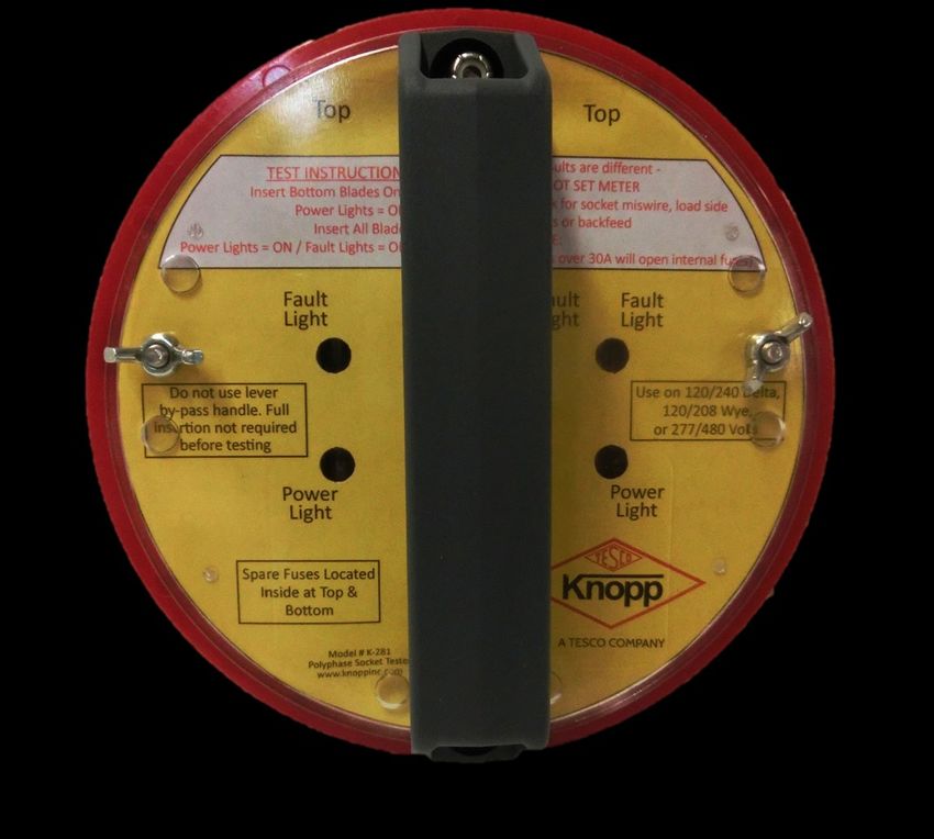
About Us. Knopp Inc., a TESCO company, is a design and manufacturing company located in Emeryville, California
alongside the beautiful San Francisco Bay.

We build high quality precision voltage and current
transformers, electric meter and transformer test
equipment, and electrical instruments for the utility and
electrical industries. Our voltage and current
transformer test equipment is used by electric utilities
throughout the world to verify the accuracy of
transformers used to measure electric energy.

History. Knopp, Inc., was founded in 1928 in then
Oakland, CA, by Otto Knopp under the name Electrical
Facilities. Mr. Knopp (pronounced KAH-NOPP) was the Chief of the Bureau of Tests and Inspection at Pacific Gas &
Electric. He had observed a need for some specific types of products and test equipment which were presently going
unfilled, and decided to begin the manufacture of some of this equipment himself.

The company was just beginning to get underway from its small, conservative start when the crash of 1929 occurred,
followed by the Great Depression. This caused years of struggling to keep the business going with year after year of
operating losses, yet Mr. Knopp continued patenting his inventions and designing new products for the fledgling
company.

In 1932, Mr. Knopp’s son Harold joined the firm. In 1936 the company made its first operating profit—a whopping
$750! In 1943 Mr. Knopp’s daughter Helen joined the firm. Harold and Helen Knopp continued to operate the company
after Mr. Knopp’s death in 1946. In 1957 the company moved to its present location in Emeryville, CA, and continued
manufacturing quality, precision items to a global
market.

In 1976, Harold and Helen decided to retire and they sold
the majority of their shares of Knopp Inc. to Quantum-
Precision Inc., a company that had been established by
two former Sangamo Electric Company employees—
Alexander Finlay and Ralph W. Karle. Mr. Karle passed
away in 1996, and Mr. Finlay passed away in 2017
leaving the future of the company uncertain.

In 2018 TESCO - The Eastern Specialty Company acquired
Knopp and continues Mr. Knopp’s legacy of building
quality, precision products for use all over the world
today.

                                             Knopp, Inc., a TESCO Company
                                          1307 66th Street, Emeryville, CA 94608
                                           510-653-1661 I www.knoppinc.com
PRODUCT CATALOG
Current Transformer Testing Systems and Standards
ANSI Standard Burden Sets
Automatic Current Transformer Comparator: KATC-C2
Automatic Voltage Transformer Comparator: KATC-V2
Burden Set—Current: BSC-102
Current Transformer Testing System: KC-1500
Current Transformer Testing System: KCTS-8000
Precision Multirange Current Transformers: P-5000 & P-12000
Voltage Transformer Testing Systems and Standards
Loading Transformer: CL-6
Precision Multirange Voltage Transformers: WP-14000
Precision Multirange Voltage Transformers: WP-36000
Uniload Voltage Transformer Test Set: 2J6
Uniload Voltage Transformer Test Set: 2J4-4
Voltage Transformer Testing System: KVTS
Hand Instruments
Low Impedance Voltage Tester: K-60
Phase Sequence Indicator: K-3, K-6, K-7
Polyphase Socket Tester: K-281
Single Phase Socket Tester: K-280
Temporary Power Outlet: K-271, K-272, K-273
Third Rail Voltage Tester: 4E2-1
Knopp, Inc., a TESCO Company
1307 66th Street, Emeryville, CA 94608
510-653-1661 I www.knoppinc.com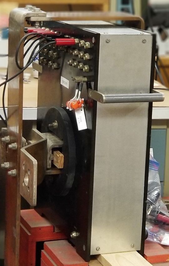
ANSI Standard
                                                                            Burden Sets
                                                                  Voltage and Current
Testing and calibrating instrument transformers often
requires standard burdens of reliable accuracy and stability,
                                                                  specifications
                                                                  Accuracy: Resistance and inductance within 1.0%
and burdens that are immune to stray fields and harmonics.
The burden sets described below have been carefully               Stability: Variation with current of the 60 Hz. impedance and power
designed to meet these requirements. They provide the                        factor of the current transformer burdens does not exceed
standard burdens required for the testing of current and                     2.0% in the range from 0.5 to 10 amperes, and the
voltage transformers for metering service, and for the testing               variation does not exceed 1.0% from 1 to 10 amperes, and
(within the current rating provided by the sets) of current                  0.5% from 2.5 to 10 amperes. Variation of either
transformers for relaying applications, all as called for by                 inductance or resistance of the voltage transformer
ANSI/IEEE C57.13-2016.                                                       burdens operated at 60 Hz. does not exceed 0.2% from
                                                                             100 to 140 volts. These data include the effects of self-
One burden set, the Type BSC-5, provides in one unit three of                heating in an ambient temperature ranging from 60⁰F to
the ANSI standard burdens for current transformers for                       80⁰F.
metering service, i.e., B-0.1, B-0.2, and B-0.5. The BSC-24 set
includes B-0.9 and B-1.8, while the BSC-25 includes all           Shielding: The maximum leakage field four inches from the cases of
metering burdens (B-0.1 through B-1.8). The heavier burdens                  the burden sets operated at rated current or voltage is less
                                                                             than 0.5 oersted. Stray 60 Hz. magnetic fields of 100
are provided by two sets. The Type BSC-8 covers the ANSI
                                                                             oersteds changes the rated current of the voltage
burdens B-1, B-2, and B-4 for current transformers for                       transformer burdens less than 0.25% and the rated voltage
relaying applications; the Type BSC-9A includes the ANSI B-4                 drop of the current transformer burdens less than 0.1%.
and B-8 burdens. In addition we offer in one unit, the BSC-10,
all burdens from B-0.1 through B-2.                               Harmonics: The percent harmonics in the voltage drop of the
                                                                          current transformer burdens is less than 1.0% throughout
All the current burden sets are designed to be used with                  the range up to 10 amperes. The percent harmonic current
external leads consisting of a 5-foot pair of #8 copper                   taken by the voltage transformer burdens is approximately
conductors. This becomes very significant at the lower                    0.2% at 80 volts, 0.3% at 120 volts, and 0.6% at 160 volts.
burden values, since the external leads constitute a
significant part of the total burden.
The standard burdens for voltage transformers (120 volt
secondaries) are covered by three sets. Three of the burdens,
i.e., W, X, and Y, are combined in one unit, the Type BSP-6
burden set. The burdens in this set are independent of each
other, each with its own pair of binding posts. The standard
burden Z is supplied in a separate unit, the Type BSP-7. Two
of these BSP-7 burden sets can be used in parallel to obtain
ANSI burden ZZ. The ANSI M burden is contained in the BSP-
20 unit.
The burden sets are of the portable type, supplied in beige
finished metal housings with engraved bakelite terminal
boards. Extensive design and development work in
perfecting these burden sets, and the quality material and
skillful workmanship employed assure excellent performance
and quality throughout.

                                                Knopp, Inc., a TESCO Company
                                             1307 66th Street, Emeryville, CA 94608
                                              510-653-1661 I www.knoppinc.com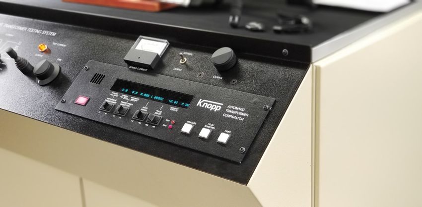
ANSI Standard Burden Sets (Cont.)
On special order, sets for frequencies other than 60 Hz. can be supplied.
Leads: Leads are not supplied with the burden sets.
All the current transformer burden sets are adjusted for a 5-foot pair of #8 closely spaced copper conductors. For the best
accuracy it is important to use equivalent leads. This is especially true for the B-0.1 burden as the leads constitute
approximately 20% of this value. If special lead size and length must be used, the burden sets can be furnished, at extra
cost, and adjusted to suit the leads specified.
With the Type BSP-6 Knopp Standard Burden Set, a pair of closely spaced #14 copper leads as much as 20 feet in length may
be used with negligible effect on the burden provided by the set. A pair of closely spaced #12 copper leads not exceeding 5
feet in length may be used with the Type BSP-7 Knopp Standard Burden Set with negligible effect on the burden provided by
the set.

                                              Knopp, Inc., a TESCO Company
                                           1307 66th Street, Emeryville, CA 94608
                                            510-653-1661 I www.knoppinc.com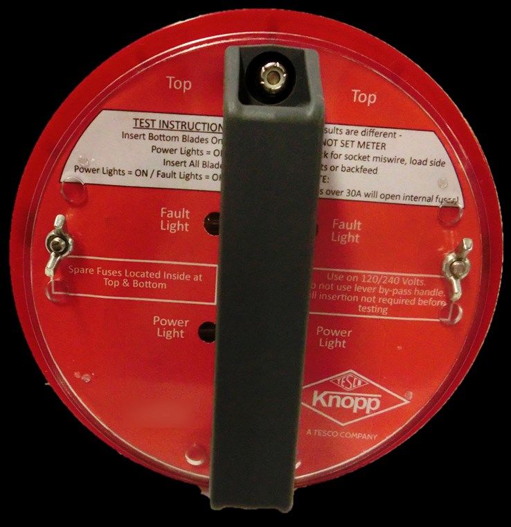
Automatic Current
Transformer Comparator
KATC-C2
issue solved specifications
Got older, slower equipment? Knopp’s KATC is faster, more Dimensions: 19” wide, 18.1” Deep, 5.25” High.
robust and more accurate! Note: This is a standard 3U rack enclosure.
Knopp’s KATC-C2 is a high accuracy current
comparator that is compatible with all older Weight: Approximately 25 pounds
generation Knopp comparators, and is designed to be a
direct, plug-in replacement requiring no Input power: 85 to 250 VAC, 2.5A, 50/60Hz
modification of the existing Knopp Current
Transformer Test Systems.
Test Frequency: 50±1 Hz, 60±1 Hz
Save time and money on service by upgrading your
comparator to our new next generation model! Standard Input: Range: 50 mA to 20 A
Phase Error: ±90 degrees
features RCF: 0 ≤ RCF ≤ 10
Easily Interchangeable with other Knopp Ratio Error: -100% ≤ Ratio Error ≤ +1000%
comparators; no modification needed Accuracy Class: 0% ≤ Accuracy Class ≤ 100%
Compatible with TESCO Test Manager Resolution: RCF: 0.00001
Ability to test transformers with 5 ampere Phase: 0.001 degrees
secondaries Accuracy Class: 0.01
Automatic sensing of 50 or 60 Hertz current
I/O Connections: I/O connection Two (2) USB 2.0 (Front
Calculation and display of ANSI accuracy class
panel)
Usage and hookup error detection and alerts, Ethernet (Front Panel)
resistant to excessive test current RS-485 Multi-drop (Rear panel/internal
Fast testing time (under one minute) communications)
Continuous instantaneous readings
Automatic operation (no manual “nulling” or Transformer
adjustments required) Inputs: S: High side reference transformer
Demag U: High side transformer under test (TUT)
Auto-ranging capability E: Low side reference transformer
Eliminated the possibility of burning up resistors by Ē: Low side transformer under test (TUT)
turning up the current too fast
5” Full color LCD, 800 x480 Related
KATC-2C-1 model allows the ability to test down to unity Equipment: KATC-2C-1 allows the ability to test down to
unity
KCTS-8000 Current Transformer Testing
System
KCTS-1500 Current Transformer Testing
System
Knopp, Inc., a TESCO Company
1307 66th Street, Emeryville, CA 94608
510-653-1661 I www.knoppinc.com
Automatic Voltage
                                                   Transformer Comparator
                                                                   KATC-V2
                                                                 specifications
                                                                 Dimensions:      19” wide x 18.1” deep x 5.25” high.
                                                                                  Note: This is a standard 3U rack enclosure.

                                                                 Weight:          Approximately 25 pounds

                                                                 Input Power:     85 to 250 VAC, 2.5A, 50/60 Hz

                                                                 Test Frequency: 50±1 Hz, 60±1 Hz

                                                                 Standard Input Range: 40V to 350V
                                                                                Phase Error: ±90 degrees
                                                                                RCF: 0 ≤ RCF ≤ 10
                                                                                Ratio Error: -100% ≤ Ratio Error ≤ +1000%
                                                                                Accuracy Class: 0% ≤ Accuracy Class ≤ 100%
                                                                                Resolution: RCF: 0.00001
                                                                                             Phase: 0.001 degrees
                                                                                             Accuracy Class: 0.01
issue solved
Got older, slower equipment? Knopp’s KATC –V2 is faster,         Resolution:
more robust and more accurate!                                                                    Phase Angle
Knopp’s KATC-V2 is a highly accurate state-of-the-art voltage                              RCF    (Minutes)         Acc. Class
transformer comparator that is compatible with all older         0.0%≤ Acc. Cl.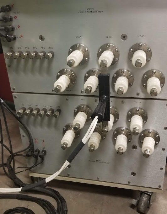
Burden Set—Current
                                                                                                         BSC-102

 introduction
 The industry has recognized the actual load (burden) on CTs
 is lower than the standard ANSI burdens allow. So a new
 IEEE Specification (IEEE C57.13.6) accommodates that fact
 by introducing two new burdens and two new accuracy
 classes. This new specification address “High Accuracy”
 CTs.

 Knopp has a new Burden Set that includes the two new
 burdens in the IEEE Specification: The E-0.04 and E-0.2
 burdens. The new Burden Set is called the BSC-102. These
 burdens are of much lower impedance than that of the
 other ANSI burdens to much more closely match the real
 world.

 testing                                                       implementation
 To test CTs using the new “High Accuracy” specification, a    All new KCTS-8000 CT Test Systems will have the BSC-102
 means to measure accuracy at lower currents is needed in      built in and the KATC-C1 will have the necessary
 addition to the new Knopp BSC-102. All new Knopp Current      modification to accommodate. The required burden (E-0.04
 Transformer test systems include a new KATC-C1                or E-0.2) is built-in and selected by the front panel Burden
 Comparator that has been upgraded to allow accuracy           select switch.
 measurements down to 4 mA (less than 1% of test current)
 instead of the previous 4%. Older KATC-C and KATC-C1        Existing installations of the KCTS-8000 CT Test System can
 Comparators can be modified to allow for this extended      be modified. The BSC-102 Burden Set box can be mounted
 range testing with the new BSC-102.                         on top of the KCTS and connected to the “external burden”
                                                             terminals. The Comparator would have to be returned for
 Note that this Comparator modification also allows accuracy modification at Knopp.
 measurements of all “Extended Range” CTs.

specifications
Here are characteristics of the BSC-102:

    Burden                                    Inductance
                     Resistance (Ohms)                          Impedance (Ohms)         Volt-amperes           Power factor
  Designation                                (millihenrys)
     E-0.04                 0.04                  0.0                   0.04                  1.0                   1.0
      E-0.2                 0.20                  0.0                   0.20                  5.0                   1.0

Dimensions:      The approximate overall dimensions of the BSC-102 is 8-1/4” long x 7-1/4” wide x 7-3/4” high

Weight: The net weight of the BSC-102 is approximately 7 pounds.

                                              Knopp, Inc., a TESCO Company
                                           1307 66th Street, Emeryville, CA 94608
                                            510-653-1661 I www.knoppinc.com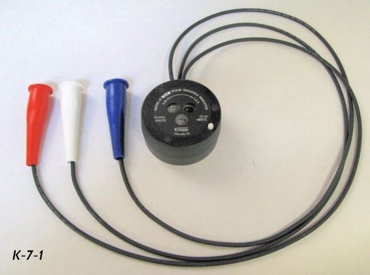
Current Transformer
Testing System
KC-1500
description operation
The Knopp Type KC-1500 Current Transformer Testing System is The desired ANSI burden is connected to the test system. The
designed to measure the accuracy of instrument transformers having required primary range is selected by a rotary switch in combination
1 and 5 ampere secondaries and primaries of up to 1500 amperes. with the use of the appropriate test terminals on the KC-1500. After
The KC-1500 is capable of testing transformers with 1 or 5 ampere the TUT is connected, and the test current adjusted, the HOLD push-
secondaries. The system uses a high accuracy multi-range current button on the Comparator is pressed. This holds the results on the
transformer as a reference standard. Comparator display while the operator returns the test current to
zero. After the test results are recorded or printed, RESET is pressed
The system is well suited for utilities whose current transformer to prepare the system for the next test.
testing needs include primary currents up to and including 1500
amperes. The phase angle and ratio errors of the transformer-under-
test (TUT) are measured by the built-in Knopp Automatic Transformer
Comparator. specifications
dimensions: Console 1: 65” (16.5 cm) High, 30.3” (77.0 cm)
Some of the standard features of the KC-1500 are: Wide, 16.0” (40.6 cm) Deep
AUTOMATIC and AUTORANGING Type KATC-C1 Current Console 2: 9.5” (24.1 cm) High, 28.2” (71.6 cm)
Transformer Comparator provides minimum measurement time Wide, 24.7” (62.7 cm) Deep
(typically within three seconds after adjustment of test current).
DIGITAL DISPLAY of test current, ratio error (in Percent or Ratio weight: Console 1: 55 pounds (24.9 kg)
Correction Factor), and phase angle error (in Minutes or Console 2: 95 pounds (43.1 kg)
Milliradians).
note: Weight does not include Burden sets or Hardware
ACCURACY CLASS for which the TUT qualifies is digitally calculated and cable connection kit
and displayed.
SELF CHECK feature allows the KC-1500 system accuracy to be input power: 120 VAC, single phase, 60 Hz, at 15 amperes
easily verified without the use of an external reference standard. maximum
PROTECTIVE CIRCUITRY senses error conditions, such as wrong
ratio or wrong polarity, and removes power from the KC-1500 system accuracy: Within ± 0.025% on ratio and ± 2 minutes on
loading circuitry. phase angle at 1.2, or less, accuracy class
ZERO START feature requires that the test current control be at
zero before power can be applied to the loading circuitry (and thus test current 5, 10, 15, 20, 25, 30, 40, 50, 75, 100,
the TUT). ranges: 150, 200, 300, 400, 500, 600, 800, 1000, 1200, and
STANDARD ANSI BURDENS include B-0.1/B-0.2/B-0.5/B-0.9/B-1/ 1500 amperes
B-1.8
PORTABILITY means the system can easily be transported to a field
testing location.
SERIAL (RS-232C) output port to allow transfer of test results to a
printer or computer.
120 VOLT OPERATION allows the use of readily available power
sources in the lab or the shop
CONNECTION KIT which includes cables to facilitate connection of
most instrument transformers to the KC-1500 terminals.
options include:
Additional ANSI BURDENS for relay testing and other purposes are
also available including B-1/B-2/B-4/B-8.
Burdens up to B-1.8 are rated for 400% tests while the remaining
burdens (B-2, B-4, B-8) are rated for 200% tests.
Knopp, Inc., a TESCO Company
1307 66th Street, Emeryville, CA 94608
510-653-1661 I www.knoppinc.com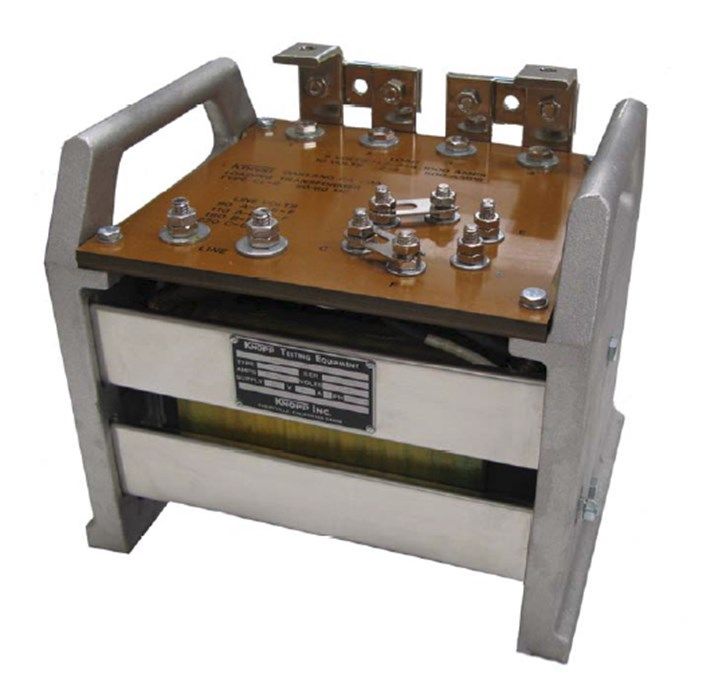
Current Transformer
Testing System
KCTS-8000
description specifications
The Knopp Current Transformer Testing System (Type KCTS-8000) is dimensions: 45” (114 cm) High, 55.5” (141 cm) Wide, 35” (89
designed to measure the accuracy of instrument transformers cm) Deep
having 1 or 5 ampere secondaries and primaries of up to 8000
amperes. The system uses a high accuracy current transformer as a weight: 1330 lbs. (603 kg)
reference standard. All ANSI standard burdens are included. The
phase angle and ratio errors of the transformer-under-test (TUT) are input power: 208 or 240 VAC (specify at time of order), single
measured by the built-in Knopp Automatic Transformer Comparator. phase, 60 Hz, at 200 amperes maximum. And a
separate 120 VAC source at 5 amperes.
Standard features of the KCTS include:
system accuracy: Within ± 0.025% on ratio and ± 2 minutes on
AUTOMATIC and AUTORANGING Type KATC-C1 Current phase angle at 1.2, or less, accuracy class
Transformer Comparator provides minimum measurement time
(typically within three seconds after adjustment of test current). test current 5, 10, 15, 20, 25, 30, 40, 50, 60, 75, 80,
DIGITAL DISPLAY of test current, ratio error (in Percent or Ratio ranges: 100, 120, 125, 150, 160, 200, 250, 300, 400, 500,
Correction Factor), phase angle error (in Minutes or Milliradians), 600, 750, 800, 1000, 1200, 1500, 1800, 2000,
and Accuracy Class of the TUT. 2500, 3000, 4000, 5000, 6000, 7500, and 8000
SELF CHECK feature allows the KCTS system accuracy to be easily amperes
verified without the use of an external reference standard.
PROTECTIVE CIRCUITRY senses error conditions, such as wrong 400% tests shall be able to be performed on all
ratio or wrong polarity, and then removes power from the KCTS ranges up to, and including 2000 amperes. 200%
loading circuitry. tests shall be able to be performed on all ranges
up to, and including, 4000 amperes.
ZERO START feature requires that both coarse and fine test
current controls be at zero before power can be applied to the Included ANSI
loading circuitry (and thus the TUT). burdens: E-0.04 (extended range), E-0.2 (extended range),
MOTORIZED CONTROL of the test current is provided to minimize B-0.1, B-0.2, B-0.5, B-0.9, B-1.8
test time. This allows AUTOMATIC RUNDOWN of the test current
after the test is complete. Relaying burdens: B-1, B-2, B-4, B-8
SERIAL (RS-232C) output port to allow transfer of test results to a
printer or data collection system. Burdens up to B-1.8 are rated for 400% tests
CONNECTION KIT which includes cables to facilitate connection of while the remaining burdens (B-2, B-4, B-8) are
most instrument transformers to the KCTS terminals. rated for 200% tests. Provisions are made for use
ANSI BURDENS 0.04 through 8 (see list of included burdens) and of an external burden.
good down to Accuracy class 0.15 Testing.
DEMAGNETIZATION of Transformers prior to test.
operation
Demagnetize transformer prior to test. The desired ANSI burden is
selected by a rotary switch, while the required primary range is
selected by a rotary switch in combination with the use of the
appropriate test terminals on the KCTS. After the TUT is connected,
and the test current adjusted, the HOLD push-button on the
Comparator is pressed. This holds the test results on the Comparator
display while the motorized test current control is automatically
returned to zero. After the test results are recorded or printed,
RESET is pressed to prepare the system for the next test.
Knopp, Inc., a TESCO Company
1307 66th Street, Emeryville, CA 94608
510-653-1661 I www.knoppinc.comPrecision Multirange
Current Transformers
P-5000 & P-12000
200% can be applied on a 25% duty-cycle basis in which the “ON”
introduction period does not exceed 30 minutes.
This Type P-5000 transformer is a laboratory standard. The unit’s
excellent accuracy and the Knopp One-to-One calibrating feature The transformer housing insulates the inserted primary from the
make this precision transformer well-suited as a standard for secondary and primary windings for up to 2500 volts. The wound
calibration work. This transformer can provide a very accurate primary is for use on circuits not exceeding 250 volts.
determination of the ratio and phase angle characteristics of current
instrument transformers having ratios from 5 to 5,000 amperes.
This transformer also can accurately extend the range of a 5 ampere specifications
ammeter or wattmeter to cover all current values up to 5,000 dimensions: The approximate overall dimensions of the Type
amperes. P-5000 are 11.5” (29.2 cm) wide, 4.5” (11.4 cm)
deep, and 13.875” (35.2 cm) high.
primary ranges weight: The net weight of the Type P-5000 is
The P-5000 provides eight self-contained primary ranges from 5 to approximately 32.5 pounds (14.7 kg) and the
100 amperes. These ranges are brought out to binding posts on the shipping weight is approximately 50 pounds
top of the transformer. A 240 turn secondary is provided for use (22.7 kg).
with these primary taps; other secondary taps are provided for other
ranges as described below. Ranges above 100 amperes are obtained
by passing a primary conductor through the transformer window.
Various primary ranges are obtainable by varying the number of Type P-12000
through-turns and choosing from among the available secondary The Type P-12000 Precision Multi-Range Current Transformer
taps. These ranges are: 125, 150, 200, 240, 250, 300, 375, 400, 500, has the following taps:
600, 625, 750, 800, 1000, 1200, 1250, 1500, 2000, 2500, 3000, 4000,
and 5000A. 2000 Amps, 3000 Amps, 4000 Amps, 5000 Amps, 6000 Amps,
7000 Amps, 7500 Amps, 8000 Amps, 9000 Amps, 10,000 Amps,
And 12,000 Amps
burden and accuracy
The Type P-5000 Transformer, like other Knopp Precision Multirange Dimensions: The approximate overall dimensions of the Type
Transformers, has excellent ratio and phase angle characteristics P-12000 are 15” wide, 4.75” deep, and 15” (35.2
with respect to both inter-range accuracy and overall accuracy. This cm) high
is made possible through a properly engineered design and through
exclusive, highly perfected compensating and winding methods. Weight: The net weight of the Type P-12000 is
approximately 35 pounds (14.7 kg) and the
The transformer is designed and compensated for the highest shipping weight is approximately 50 pounds
possible accuracy at the burden specified by the purchaser, but also (22.7 kg)
may be used with excellent results with other burdens up to 25 volt-
amperes. When used with the burden for which compensated, the
ratio of this transformer standard is well within ± .02% and the
phase angle is well within 2 minutes on all ranges.
calibration
A Report of Calibration, traceable to the National Institute of
Standards and Technology (NIST) is included with the transformer.
We recommend that the accuracy of the transformer be checked by
a certified laboratory every five (5) years. Additionally, the One-to-
One accuracy of the transformer can be checked when desired by
comparing the 5 ampere primary tap to the 5 ampere (240 turn)
secondary. Any reliable error-measuring instrument can be used for
this purpose. One-to-One data will be included with this
transformer when shipped.
rating and insulation Type P-5000
All windings are rated at 100% continuous current. Current up to
Knopp, Inc., a TESCO Company
1307 66th Street, Emeryville, CA 94608
510-653-1661 I www.knoppinc.comLoading
Transformer
CL-6
application If more capacity is required than one transformer can supply, two or
Where currents up to 1000 amperes are required, the Type CL-6 more of these transformers may be connected in parallel or series.
portable Knopp Loading Transformer is very useful in the testing and
calibrating of current-actuated protective and switching devices, Also available is the Type CL-6-S1:
current-carrying apparatus, and transformers, such as:
Output: 10 volts, 500 amperes
Sectionalizers 20 volts, 250 amperes
Fuse links
Meters
Meter sockets description
Fuse boxes This readily portable Knopp Loading Transformer weighs only 60
Connectors pounds and measures only 12” long, 9” wide, and 10” high. Its
Cables sturdy enclosure provides protection and adequate ventilation. Two
Busses convenient carrying handles are provided.
Overcurrent relays
Thermal Overload relays The insulating terminal panel is rigidly secured to the transformer
Motor starter overload relays frame, and heavy-current, bus-bar-type terminals are securely
bolted to the panel. The two output terminals each have two
Oil circuit breakers
connection surfaces, one on a vertical plane and one on a horizontal
Transformer breakers
plane, for maximum convenience in connecting the heavy current
Disconnect switch contacts leads and in changing, when necessary, the series-parallel links. The
Instrument current transformers links and the output connections cannot interfere with each other.
Air circuit breakers (thermal, magnetic, and thermal-magnetic) All terminals and connection links are plated.
Both the primary and the secondary are insulated for a 4000 volt, 60
rating and ranges cycle, one-minute test. A grounding stud is provided on the
The CL-6 is a 5 KVA transformer. This unit may be used continuously enclosure.
at that output when used with rated voltage on the 110- and 220-
volt connections. It is of conservative and quality design, assuring
good waveform and dependable service under all field testing
conditions.
Frequency: 50/60 cycles
Input: Taps for 90, 110, 180, and 220 volts
Output: 5 volts, 1000 amperes (parallel connection);
10 volts, 500 amperes (series connection)
The output currents indicated are maximum for continuous duty,
and on intermittent duty the output currents may be increased to
750 amperes at 10 volts and 1500 amperes at 5 volts on a 40% duty
cycle of 20 minutes on and 30 minutes off.
A suitable variable transformer can be used to adjust the output
current to the desired value up to the output limits indicated.
Knopp, Inc., a TESCO Company
1307 66th Street, Emeryville, CA 94608
510-653-1661 I www.knoppinc.comPrecision Multirange
Voltage Transformer
WP-14000
comparing the 120 volt primary tap to the 120 volt secondary. Any
introduction reliable error-measuring instrument can be used for this purpose.
This Type WP-14000 Transformer is primarily a laboratory standard.
Its excellent accuracy and the Knopp one-to-one calibrating feature
make it well-suited as a standard for precision calibrating work. This construction
transformer makes possible very accurate determination of the ratio For long, dependable service, the coil is cast in epoxy, and the core
and phase angle characteristics of voltage instrument transformers and coil assembly is housed in a beige steel case with engraved
having ratings from 120 to 14,400 volts. This transformer also aluminum panel fitted with porcelain high-voltage bushings.
makes it possible to accurately extend the range of a 120 volt
voltmeter or wattmeter to cover all voltage values up to 14,400
volts. specifications
dimensions: The approximate overall dimensions of the Type
Several versions of the WP-14000 Transformer exist. These versions WP-14000 are 20” (50.8 cm) wide (not including
are differentiated by affixing a suffix to the Type designation (e.g. the handles, 15” (38.1 cm) deep, and 18” (45.7
WP-14000-4). The differences among the versions generally lie in cm) high including the bushings.
the number and value of the intermediate voltage ranges. As an
example, the WP-14000-4 transformer includes 288 and 300 volt weight: The net weight of the Type WP-14000 is
ranges not found on the WP-14000-1 transformers. approximately 175 pounds (79.4 kg) and the
shipping weight is approximately 250 pounds
(113.4 kg). The dolly’s net weight is 17 pounds
primary ranges (7.7 kg), and its shipping weight is approximately
The primary ranges for the WP-14000-4 are: 30 pounds (13.6 kg).
120, 240, 288, 300, 480, 600, 2400, 4800, 7200, 8400, 12,000 and
14,400 volts. The secondary is 120 volts.
burden and accuracy
The WP-1400 Transformer, like other Knopp Precision Multirange
Transformers, has excellent ratio and phase angle characteristics
with respect to both inter-range accuracy and overall accuracy. This
is made possible through a properly engineered design and through
exclusive, highly perfected compensating and winding methods.
The transformer is furnished compensated for the highest possible
accuracy at the burden specified by the purchaser, but it may be
used with excellent results with other burdens up to 25 volt-
amperes. When used with the burden for which compensated, the
ratio of this transformer standard is well within 0.02% and the phase
angle is well within 2 minutes on all ranges.
calibration
A Report of Calibration, traceable to the National Institute of
Standards and Technology (NIST) is included with the transformer.
We recommend that the accuracy of the transformer be checked by
a certified laboratory every five (5) years. Additionally, the one-to-
one accuracy of the transformer can be checked when desired by
Knopp, Inc., a TESCO Company
1307 66th Street, Emeryville, CA 94608
510-653-1661 I www.knoppinc.comPrecision Multirange
voltage transformer
WP-36000
One feature, the benefit of the One-to-One calibration can be
introduction extended to the WP-36000 by comparing the 14400-volt ranges of
This Type WP-36000 Transformer is primarily a laboratory standard. the two transformers, using the WP-14000 as the standard.
The high degree of accuracy and multiplicity of ranges makes this
transformer the standard for precision calibration work. With the aid
of this transformer, very accurate determination can be made of the
description
This transformer is oil-insulated and is equipped with high-voltage
ratio and phase angle characteristics of voltage transformers having
cast-glass bushings. The plus-minus end of the winding is grounded
ratings from 14,400 to 36,000 volts.
to the core and case, and the transformer should be grounded
through the ground terminal provided.
Additionally, the range of a voltmeter or wattmeter can be
accurately extended by this transformer to cover all voltage values
from 14,000 to 36,000 volts. specifications
dimensions: The approximate overall dimensions are:
primary ranges 30” (76.2 cm) wide, 24” (609.6 cm) deep, and
32” (812.8 cm) high, including bushings.
Several models are available. The models are differentiated by the
two intermediate ranges:
weight: The net weight is approximately 570 lbs. (259
kg), and the shipping weight is approximately
Model WP-36000-1: 14400, 18000, 20760, and 36000 volts.
700 lbs. (318 kg).
Secondary: 120 volts
Model WP-36000-2: 14400, 16800, 24000, and 36000 volts.
Secondary: 120 volts
Model WP-36000-3: 14400, 21000, 24000, and 36000 volts.
Secondary: 120 volts
Other intermediate ranges are available. Consult Knopp for more
information.
burden and accuracy
The WP-36000 Transformer, like other Knopp Precision Multirange
Transformers, has excellent ratio and phase angle characteristics
with respect to both inter-range accuracy and overall accuracy. This
is made possible through a properly engineered design and through
exclusive, highly perfected compensating and winding methods.
The transformer is furnished compensated for the highest possible
accuracy at the burden specified by the user, but it may be used
with excellent results with other burdens up to 25 volt-amperes.
When used with the burden for which compensated, the ratio of this
transformer standard is well within ±0.02% and the phase angle is
well within 2 minutes on all ranges.
calibration
The WP-36000 does not provide the Knopp One-to-One Calibrating
Feature. However, for those who have a WP-14000 Knopp Precision
Multirange Voltage Transformer Standard with the Knopp One-to-
Knopp, Inc., a TESCO Company
1307 66th Street, Emeryville, CA 94608
510-653-1661 I www.knoppinc.comUniload Voltage
Transformer
2J6
introduction accuracy and burden
The Type 2J6 Knopp Uniload Voltage Transformer Test Set When the Knopp Precision Transformer in the 2J6 set is
consists of three major parts: compensated for, and used with, a secondary burden of 15 volt-
amperes, for example, the ratio of this precision transformer is well
within 0.02% and the phase angle is well within 2 minutes. The
A Knopp Precision Multirange Voltage Transformer
transformer, in common with other Knopp Precision Multirange
Standard with four primary ranges (from 14,400 volts to Transformers, is wound so that it has practically the same ratio and
36,000 volts) and a 120 volt secondary. phase angle accuracy on all ranges.
A Knopp Heavy-Duty Supply Transformer with a primary of
either 120 volts or 240 volts (as ordered) and with
secondary ranges the same as the primary ranges of the calibration
precision transformer standard. The transformer standard can be checked against any 14,400 volt
transformer standard, such as the Type WP-14000 Knopp Precision
A mounting base which aligns and supports the above two
Multirange Voltage Transformer
transformers.
This Type 2J6 test set is available in various models shown in
the following table. Custom versions are also available. dimensions and weight
The equipment measures approximately 38.75” wide, 23.75” deep,
and 30” high. The net weight is approximately 1,220 pounds.
For convenience and safety, a special high-voltage connection
bar and lead set for selecting the proper voltage range on the
supply transformer and precision standard are provided with
each 2J6 set. The connection bar is designed to prevent
incorrect connections during tests.
The Knopp Supply Transformer mounts alongside the Knopp
Precision Transformer with an interlocking feature for rigidity.
Hook-eyes are also provided on the top of each transformer
for lifting.
Knopp, Inc., a TESCO Company
1307 66th Street, Emeryville, CA 94608
510-653-1661 I www.knoppinc.comUniload Voltage
Transformer
2J4-4
introduction primary ranges
The Type 2J4-4 Knopp Uniload Voltage Transformer Test Set The primary ranges for the 2J4-4 are:
consists of three major parts:
120/240/288/300/480/600/2400/4200/4800/7200/8400/12000/
14400 volts.
A Type WP-14000-4 Knopp Precision Multirange Voltage
Transformer Standard with primary ranges of 120; 240; All ranges are referenced to a 120 volt secondary.
288; 300; 480; 600; 2,400; 4,200; 4,800; 7,200; 8,400;
12,000; and 14,400 volts. Secondary: 120 volts.
A Type LP-14000-4 Knopp Heavy-Duty Supply Transformer specifications
(similar in size and appearance to the WP-14000-4). The equipment measures approximately 23” wide (not including
A rubber-tired carriage which supports the WP-14000-4 handles), 15” deep, and 40” high.
and LP-14000-4 and provides mobility to the complete
The net weight is approximately 500 pounds.
Uniload Test Set.
For convenience and safety, a connection arrangement which
prevents incorrect connections during tests is used for
selecting the proper voltage range on the supply transformer
and the precision standard.
The Type LP-14000 Knopp Supply Transformer mounts on top
of the Type WP-14000-4 Knopp Voltage Transformer, with an
interlocking feature for rigidity. Handles are also provided on
each transformer for an added convenience should you wish
to use the transformers separately and away from the
carriage.
accuracy and burden
When the Type WP-14000-4 Precision Standard Transformer is used
with a secondary burden of 15 volt-amperes, to give an example, the
ratio of this voltage transformer is well within .02% and the phase
angle is well within 2 minutes. The transformer is wound so that it
has practically the same ratio and phase angle accuracy on all
ranges.
calibration
The transformer standard can be calibrated by itself without a
standard of comparison by means of the Knopp One-to-One
method.
Knopp, Inc., a TESCO Company
1307 66th Street, Emeryville, CA 94608
510-653-1661 I www.knoppinc.comVoltage Transformer
Testing System
KVTS
Comparator is pressed. The results will be automatically sent to a
description computer/data collection system.
The Knopp Voltage Transformer Testing System is designed to
measure the accuracy of instrument transformers having 120 volt
secondaries and up to 14,400 volt primaries (special order for up to
36,000 volt primaries is available). The system includes a control specifications
console which contains the control circuitry, ANSI standard burdens, dimensions: 61.5” (156.5 cm) High; 24” (61 cm) Wide;
and the Knopp Automatic Transformer Comparator. The Knopp 37” (94cm) Deep (console) and 36” (91.5 cm)
precision and loading transformer set is also included (see picture High; 25” (63.5 cm) Wide; 20” (50.8 cm) (Deep)
below) and is connected to the console via a special cable. Voltage Test Set
Some of the features of the KVTS are: weight: 350 lbs. (159.7 kg) (console) and 300 lbs.
(transformer test set)
AUTOMATIC and AUTORANGING Voltage Transformer
Comparator (Type KATC-V) provides minimal measurement time input power: 120 VAC, 60 Hz; single phase; 10 amperes
(typically a few seconds after adjustment of test voltage). maximum
DIGITAL DISPLAY of test voltage, ratio error (in percent or ratio system accuracy: Within ±0.025% on ratio and ±2 minutes on
correction factor), and phase error (in minutes or milliradians) is phase angle at 1.2 accuracy class or less.
provided by the Comparator (KATC-V).
primary ranges: 120 / 240 / 288 / 300 / 480 / 600 / 2,400 /
4,200 / 4,800 / 7,200 / 8,400 / 12,000 / 14,400
ACCURACY CLASS for which the transformer-under-test qualifies volts.
is calculated and digitally displayed by the Comparator (KATC-V).
Consult factory on other ranges.
SELF CHECK feature allows the system accuracy to be easily
verified without the use of an external standard. burdens: ANSI W, X, M, Y, Z, and ZZ; switch selectable.
Provisions are made for use of an external
PROTECTIVE CIRCUITRY senses unusual error conditions such as burden.
wrong ratio or polarity and then automatically removes power
from the KVTS loading circuitry to protect the KVTS, precision connecting cable: 15 feet long (between transformer set and
transformer, and the transformer-under-test. console).
ZERO START feature requires that both coarse and fine controls of
test voltage be at zero before power can be applied to the
loading circuitry.
COMPUTER or PRINTER communication is available through an RS
-232 port.
VOLTAGE TRANSFORMER TEST SET includes a high precision multi
-range voltage transformer and a heavy duty supply transformer
plus the T-bar assembly and wheeled base.
INTERCONNECTING CABLES between the control console and the
transformer test set.
All ANSI BURDENS including W, X, M, Y, Z and ZZ.
operation
The desired ANSI burden is selected by a rotary switch on the
console. The appropriate range is selected at the precision/loading
transformer set. After the operator connects the transformer-under
-test and adjusts the test voltage, the HOLD button on the
Knopp, Inc., a TESCO Company
1307 66th Street, Emeryville, CA 94608
510-653-1661 I www.knoppinc.comLow Impedance
Voltage Tester
K-60
FOR AC AND DC 120 TO 600 VOLTS
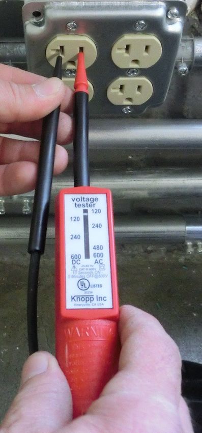
MODEL K-60 KNOPP VOLTAGE TESTER for AC and DC with polarity indicator.
Double safety indication is by solenoid and by neon lamp.
GENERAL DESCRIPTION: Knopp Voltage Testers offer portability and ease of
use with full protection. These exceptionally versatile and useful tools are
backed by a reputation for quality in the design and manufacture of electrical
test equipment.
FEATURES
SAFE AND DEPENDABLE: Knopp Voltage Testers are designed and build with
safety, the key criteria! Dual voltage indication is provided by solenoid and
neon lamp, operating independently. The lamp gives a bright warning signal.
Voltages are shown by a positive, easy-to-read, moving indicator. There is a
signal by hum and vibration; and the user is protected by high-grade, properly
applied insulation, and by separation of incoming leads (they do not cross over
each other within the housing). Interior separation of the circuit is a basic
design feature of the case.
Nylon insulation covers prod tips to within 9/16” of end to prevent shorts
across tips. The K-60 has no exposed metal parts. The scale and plate are both
of insulating material.
DURABLE: The rugged Cycolac housing and sturdy internal chassis of
Polysulfone – each of one-piece construction – are securely interlocked and
designed for durability and hard use. All electrical connections are soldered.
U.S. MADE: The K-60 is manufactured entirely in the United States.
Knopp, Inc., a TESCO Company
1307 66th Street, Emeryville, CA 94608
510-653-1661 I www.knoppinc.comLow Impedance Voltage Tester (Cont.)
specifications unique dual-mounting system makes possible single-hand
testing.
Voltage Measurements: Operating on the solenoid Stainless Steel Prods / Flat-Tip Design: Prods are made
principle, these dependable Knopp Voltage Testers tell from hard stainless steel, which will not rust and which
whether the circuit is opened or closed, indicate the resists wear and bending; the ends of the prods are
nominal AC circuit voltages of 120, 240, 480, and 600, and especially flattened to facilitate using the prods in narrow
the nominal DC circuit voltages of 120, 240, and 600, openings (such as small convenience outlets).
whether the voltage is 25 or 60 Hz. Prod Insulation: Sturdy, 4” long laminated phenolic prod
Polarity Determination: The polarity of DC circuits can be handles provide tough, moisture and oil-resistant non-
quickly and positively determined with the neon-light warping insulation. The stainless steel tips are nylon-
polarity indicator featured in the Knopp K-60 model. insulated to within 9/16” of the point for additional
protection. Thus, the operator has the protection of more
A-C, Pure DC, and Rectifier DC Identification: Vibration than 5” of insulation, and there is almost no chance of
and humming of the testers indicate that the circuit is AC causing shorts between prods.
or unfiltered rectified DC, since there is no hum or
vibration with pure DC. Rectifier DC (pulsating DC) can be QUALITY DESIGNED … QUALITY BUILT: Knopp products
easily distinguished from AC with the aid of the neon lamp are backed by more than 70 years of experience in the
in the tester. design and manufacture of electrical test equipment.
Knopp, Inc., pioneered numerous major improvements in
Compactness and Ease-of-Handling: The Knopp Voltage voltage test devices, including dual voltage indication,
Tester features its exclusive, cylindrical SLIM-GRIP design polarity indication, strain relief lead anchorage in both
that fits securely and comfortably in your hand, and in case and prod handles, the use of stainless steel for prod
addition, the K-60 provides the alternative “pistol grip” for tips, and the prod mount. Knopp quality and dependability
reaching into deep and tight test places. The housing are bywords in the industry and are your assurance the
diameter is less than an inch and a quarter (1.25”). When Knopp Voltage Testers are the best ever built,
the prods are stored, the K-60 is exceptionally compact incorporating every possible advance in design and quality
and is easily carried in the pocket or pouch. And the construction.
Fused leads are available at an additional cost.
Knopp, Inc., a TESCO Company
1307 66th Street, Emeryville, CA 94608
510-653-1661 I www.knoppinc.comPhase Sequence
Indicators
K-3, K-6, K-7
ROTARY TYPE ● NO LAMPS ● RELIABLE ● RUGGED ●
VERSATILE ● TIME SAVING
POSITIVE, STRAIGHTFORWARD SEQUENCE INDICATION IS PROVIDED over
a wide variety of voltage and frequency by direction of rotor rotation. No
need for range switching or terminal changing. Also indicates an open
phase.
MODELS K-3: 60-600 volts, 25-60 Hz
MODEL K-6: 24-480 volts, 400 Hz
MODEL K-7: 60-600 volts, 25-60 Hz
K-7 has several options with different lead lengths and colors.
See back of brochure for application on other frequencies.
Use of the Knopp Phase Sequence Indicator saves man-hours and protects
valuable equipment against damage. It pays for itself in a short time.
of the switch, the Indicator clips can be Indicator is to indicate the order of succession
specifications left connected to the circuit-under-test in time of the different voltage peaks of a
between “before” and “after” readings of multiphase supply. In addition, the Knopp
The following salient features are reasons for the phase sequence – timesaving and Sequence Indicator enables one to make
this instrument’s proven reliability and long error preventing. Between these tests continuity tests. It is a valuable instrument in
life, for its convenience, simplicity, and safety the instrument can be left hanging from diverse fields involving polyphaser power
in use and for its durability in rigorous service. the clips. apparatus, being employed by line and
installation crews for public utility systems
5. There are no exposed metal parts. The and industrial-plant electrical departments. It
1. Specially designed induction motor instrument housing is made of laminated is, furthermore, helpful in the testing
unmistakably indicates the phase phenolic, and is cylindrically shaped, an departments of public utility systems for
sequence by direction of rotation of rotor exceptionally rugged service-proven laboratory and field testing.
disc. construction. The three window panes
are small and deeply recessed for The Knopp Phase Sequence Indicator is used
2. The Lead Set is permanently connected protection from impacts. in connection with the making of three-phase
to the instrument to save testing time circuit installations or alterations, and
and prevents errors in connecting. 6. Good visibility of the rotor movement is replacement installations of motors and
assured. The black area o the aluminum generators, also for making continuity tests of
3. For ease and certainty in identifying rotor blacks out windows in phase circuits of polyphase systems. Moreover, it is
connections, the test clips are sequence. valuable in making connections of power-
permanently marked with letters A, B, factor meters, volt-ampere meters, watt and
and C, and the corresponding flexible 7. Only 21 oz. in weight, the indicator is watthour meters, and relays. Some of these
leads and clip insulators are coded red, small and easily carried. applications are discussed in the following
white, and blue. paragraphs.
4. The patented circuit and switch applications (continued)
arrangement makes for instrument
protection and personnel safety. Because The primary function of the Phase Sequence
Knopp, Inc., a TESCO Company
1307 66th Street, Emeryville, CA 94608
510-653-1661 I www.knoppinc.comPhase Sequence Indicators (Cont.)
the Knopp Sequence Indicator, there is no
applications need for making tight connections until the
Open-Phase Indication
correct order has been established.
Phasing-In Power Circuits After Alterations The presence of an open circuit in at least one
phase of a three-phase supply is indicated by
The most frequent application for the Knopp
Motor and Generator Terminal Markings the failure of the Sequence Indicator to rotate
Phase Sequence Indicator is for phasing-in a
when connected to the circuit.
power line which has supplied power to It will be obvious that the Knopp Sequence
motors and plants, and where line alterations Indicator may be used to correlate definitely
are made in the circuit feeding this line. It is the motor and generator conductor markings
necessary to determine the sequence before with the phase sequence of applied or Six-Phase Sequence
alteration is made so that the same sequence generated voltage. The Indicator can be used to determine the
can be reestablished for the consumer by the phase order of six-phase circuits by arranging
line crew after alteration has been made. This the six terminals into two groups of three, each
will avoid any possibility of damage incident to Connections of Polyphase Power-Factor group having equal voltage between all pairs of
reversing the consumers’ motors and Meters terminals and both groups having the same
machinery. sequence, the two 3-phase triangles should
Where instrument transformers are employed form a hexagon with equal voltage sides.
Connecting Motors and Generators for power factor metering, mistakes are easily
Use of the Knopp Sequence Indicator protects made in the connections. The phase sequence
apparatus and enhances service efficiency. By of the input current for the current coils should The Knopp Phase Sequence Indicator includes
indicating which terminals of a newly installed be checked for the correct order of a three-phase induction motor having an
polyphaser power circuit are to be connected attachment, as indicated by the
aluminum-disc rotor mounted for free rotation
to the sequence-identified motor terminals, it manufacturer’s diagrams. The phase sequence on a cushioned glass-hard bearing and having
eliminates the trial-and-error method and thus of the voltage coils is determined by the field windings placed at 120 geometrical-
prevents damage and saves time. Sequence Indicator.
degree intervals about the rotor axis. One
terminal of each winding is extended beyond
the case to a distinctly colored conductor and
Obviously the trial-and-error method is not Reactive-Volt-Ampere Connections to a lettered test clip for attachment to one
permissible for direct-connected electric When varmeters are being connected in conductor of the tested system; and the
motors which, because of the nature of the polyphaser circuits, it is necessary to use the second terminal of each winding is connected
machines they drive, cannot be operated in correct phase order so as to assure the correct to one of three contacts of the insulated
reverse. Furthermore, reversal of a generator’s meter indications. The Knopp Indicator protector-switch. The protector-switch must
phase rotation when being paralleled would furnishes direct and positive means of be held closed to energize the windings and is
result in a short circuit. determining the proper sequence. so arranged that accidental or even continuous
closure of the switch is unlikely.
The flexible cable withstands severe handling
Suppose a three-phase motor load is to be Two-Phase, 3-Wire Operations and is intended for suspending the instrument
connected to a new set of three-phase from the line wires or terminals with the test
conductors. Before a change is made, the The Knopp Sequence Indicator (catalog No. clips. The free ends of the conductors are
original power sequence to the load is 44030, 3-phase, 3-wire type) will operate shorter than the sheathed portion so that,
determined by attaching the Sequence satisfactorily on 2-phase, 3-wire systems. when the instrument is suspended, a detached
Indicator to the line side of the motor switch. However, it should be noted that on such clip cannot contact the operator while the
After temporary new connections are made, systems the voltage between the outers is 1.4 switch is closed. Since the cable is anchored in
the line is again energized and the phase times the phase voltage. This factor should be the sealed housing, clockwise rotation of the
sequence checked. If the original sequence is taken into consideration when using the rotor always means that the phase order of the
reversed, two of the new conductors can be Indicator on higher voltage circuits, bearing in tested terminals is that of the marks A, B, C, on
interchanged to give the original sequence. mind the voltage rating of the instrument. the clips attached thereto.
Since only minute power is required to operate
* Suitable for use on frequencies above 60 Hz, provided the circuit voltages are equal to, or exceed, the following: 150 volts for
133 Hz; 200 volts for 180 Hz; 250 volts for 360 Hz; 300 volts for 400 Hz.
Knopp, Inc., a TESCO Company
1307 66th Street, Emeryville, CA 94608
510-653-1661 I www.knoppinc.comPhase Sequence Indicators (Cont.)
MODEL LEADS VOLTAGE HERTZ PHASE COLOR
K-3 ONLY 36” LONG 60 TO 600 25 TO 60 A—RED
B—WHITE
C—BLUE
K-3-1 36” LONG 60 TO 600 25 TO 60 A—RED
B—YELLOW
C—BLUE
K-3-2 36” LONG 60 TO 600 25 TO 60 A—RED
B—GREEN
C—BLUE
K-3-3 36” LONG 60 TO 600 25 TO 60 A—RED
PANEL MOUNT B—WHITE
C—BLUE
K-3-4 36” LONG 60 TO 600 25 TO 60 A—RED
B—BLUE
C—BLACK
K-3-4S 36” LONG 60 TO 600 25 TO 60 A—RED
B—BLACK
C—BLUE
K-3-5 60” LONG 60 TO 600 25 TO 60 A—RED
(1’ Sheath only) (Oversized clips B—WHITE
& Ins.)* C—BLUE
K-3-7 50” LONG 60 TO 600 25 TO 60 A—RED
(normal B—WHITE
sheathing) C—BLUE
K-3-7S 50” LONG 60 TO 600 25 TO 60 A—RED
(normal B—BLUE
sheathing) C—GREEN
K-6 36” LONG 24 TO 480 400 A—RED
B—WHITE
C—BLUE
K-6-3 36” LONG 24 TO 480 400 A—RED
PANEL MOUNT B—WHITE
C—BLUE
K-7 26” LONG 60 TO 600 25 TO 60 A+1—BLACK
(3 individual) B+2—WHITE
C+3—RED
K-7-1 36” LONG 60 TO 600 25 TO 60 A—RED
(3 individual) B—WHITE
C—BLUE
K-7-2 72” LONG 60 TO 600 25 TO 60 A—RED
(3 individual) B—WHITE
C—BLUE
K-7-3 50” LONG 60 TO 600 25 TO 60 A—RED
(3 individual) B—WHITE
C—BLUE
K-7-4 36” LONG 60 TO 600 25 TO 60 A+1—BLACK
(3 individual) B+2—WHITE
C+3—RED
*Oversized clip=40A; 3/4” Opening. Normal clip=20A; 5/8” Opening.
Knopp, Inc., a TESCO Company
1307 66th Street, Emeryville, CA 94608
510-653-1661 I www.knoppinc.comPolyphase Socket
Tester
K-281
functionality
Knopp’s K-281 Polyphase Socket
Tester is designed to detect dangerous
backfeed conditions, grounds, short
circuits and wiring errors in either a
120/240, 120/208, or 277/480 volt meter
socket. Also available in a Canadian
Polyphase (347/600 volt).
It is equipped with high intensity
Power Lights and Fault Lights to show
whether or not the meter is safe to set.
The Polyphase Socket Tester also comes
with a heavy duty handle for quick and
easy installation.
specifications
120/240 meter socket
120/208 meter socket
277/480 meter socket
347/600 Canadian Polyphase
Sturdy handle for easy removal
6 jaw design
UV stabilized plastic
UL 94-5 VA Flame Rating
Fiberglass reinforced polycarbonate
Knopp, Inc., a TESCO Company
1307 66th Street, Emeryville, CA 94608
510-653-1661 I www.knoppinc.comSingle Phase Socket
Tester
K-280
functionality
Knopp’s K-280 Single Phase Socket
Tester is designed to detect short
circuits, backfeed and wiring errors in a
120/240 volt, 3-wire, single phase
self-contained meter socket.
This unit is equipped with high
intensity Power Lights and Fault Lights to
show whether or not the meter is safe to
set. It also comes with a heavy duty handle
for quick and easy installation.
specifications
120/240 Volt
Sturdy handle for easy removal
4 jaw design—2S Meter Form
UV stabilized plastic
UL 94-5 VA Flame Rating
Fiberglass reinforced polycarbonate
Knopp, Inc., a TESCO Company
1307 66th Street, Emeryville, CA 94608
510-653-1661 I www.knoppinc.comTemporary Power
Outlet
K-271, K-272, K-273
functionality
Knopp’s Temporary Power Outlets are an easy and
safe solution for construction sites or other areas
where power is not easily accessible. The device
provides temporary electric service by isolating
power from the breaker panel.
Easy-to-use and versatile, Knopp’s Temporary
Power Outlet eliminates the need for portable
generators and can be used for motor homes,
travel trailers, marine shore power, construction
sites, and solar pump stations. Emergency
situations such as hurricane restoration, storm specifications
outages and fire damage can also utilize this UL Listed Components
device. UV Stabilized plastic, UL 94-5VA Flame Rating
Configurations available for either Ring (R) or Weatherproof
Ringless (RL) style meters. Optional Power on Reusable
Indicator Light, and optional kit available that Lockable receptacle cover
includes a jumper cover for added safety.
NEMA GFCI Duplex Outlets or Twist Lock Outlets
Meets all ANSI and UL dimension requirements for 20A or 30A internal circuit breaker with external
meter sockets. reset
Isolated Load Side Jaw Blades (no power is
provided to load side of meter socket)
Model Numbers Description Protection of meter with proven surge ground
system
K-271-R NEMA L14-30R Twist Lock Adapter, breakers and 20 amp GFCI outlets
K-271-RL and GFCI 20amp Standard housed in a strong fiberglass reinforced
polycarbonate housing
Safer ground-fault and overcurrent protected
K-272-R (2) GFCI 20amp Standard
electric service
K-272-RL 520 Receptacle
200A meter adapter can be fitted with either a
meter or a jumper
K-273-R Trailer/Motor Home hookup
Optional kit available for each model that
K-273-RL and GFCI 20amp Standard
includes a TESCO Cat. 277 Jumper Cover.
Knopp, Inc., a TESCO Company
1307 66th Street, Emeryville, CA 94608
510-653-1661 I www.knoppinc.comYou can also read