Oxygen Handbook - Xylem Analytics ...
←
→
Page content transcription
If your browser does not render page correctly, please read the page content below

Oxygen Handbook
MEASUREMENT TECHNOLOGY THEORY AND TIPS FOR PRACTICAL APPLICATION

Oxygen Handbook

Xylem Analytics Germany
Sales GmbH & Co. KG, WTW
Dr.-Karl-Slevogt-Straße 1
D-82362 Weilheim
Germany
Tel:        +49 881 183-0
Fax:        +49 881 183-420
Email:      Info.WTW@Xyleminc.com
Internet:   www.WTW.com
More than 70 years of experience
Dissolved oxygen is determined via a partial pressure measurement,
with the oxygen dissolved in the liquid depending on the pressure of
the gas found above the surface. In 1965 we were ready for serial pro-
duction of sensors for measuring dissolved oxygen to the market with
our WTW brand. Since then the measurement technology for this pa-
rameter, which is decisive for the lives of flora and fauna in water among
other things, has seen continuous development. Today we additionally
offer optical dissolved oxygen sensors which facilitate precise measure-
ments at lowest maintenance efforts and with highest precision.

This handbook wants to give some understanding of the measurement
technology by practical tips, support users and allow interested people
learning about the principles of measurement.

We are happy to be at your disposal at any time, just give us a call!

Dr. Robert Reining and Ulrich Schwab
(Directors of Xylem Analytics Germany GmbH)
Content

SECTION 1
Fundamentals6
  1.1 Dissolved Oxygen Sensors ��������������������������������������������������� 7

SECTION 2
Calibration and analytical quality assurance                                                 11
  2.1 Calibration ����������������������������������������������������������������������������� 11
      2.1.1 Calibration in watervapor-saturated air �������������������� 11
      2.1.2 Calibration in air-saturated water ������������������������������ 13
      2.1.3 The calibration process in the measuring meter ����� 13
  2.2 Sensor function check ��������������������������������������������������������� 14
      2.2.1 Test in water-vaporsaturated air ��������������������������������� 15
      2.2.2 Test in air-saturated water ������������������������������������������� 15
      2.2.3 Test using zero solution ����������������������������������������������� 15

SECTION 3
Measurement and analytical quality assurance                                                 17
  3.1 Cleaning the sensor ������������������������������������������������������������� 17
  3.2 Regenerating the sensor ����������������������������������������������������� 17
  3.3 Unit and display of the measuring result �������������������������� 19
      3.3.1 Display as a concentration value ������������������������������� 19
      3.3.2 Display as oxygen saturation percentage ���������������� 19
      3.4 Potential error sources ���������������������������������������������������� 20
      3.4.1 Polarization times (running-in time) before
             measurement ���������������������������������������������������������������� 20
      3.4.2 Drift check (AUTOREAD) �������������������������������������������� 20
3.4.3 Importance of flow ������������������������������������������������������ 20
3.4.4 Salt content correction ������������������������������������������������ 22
3.4.5 Impact of interferring gases ��������������������������������������� 22
3.4.6 Solubility function �������������������������������������������������������� 23
SECTION 4
Optical oxygen measurement 24
4.1 The principle of optical measurement ������������������������������ 24
4.2 Characteristics of the optical dissolved oxygen
sensors ����������������������������������������������������������������������������������� 26
4.3 Calibration of optical dissolved oxygen sensors ������������� 27
4.4 Cleaning of optical dissolved oxygen sensors ����������������� 27
4.5 Impact of interferring gases ����������������������������������������������� 28
Bibliography29
Further handbooks 30
About us 31
Information around the clock! ��������������������������������������������������� 31Oxygen Handbook
SECTION 1 tial pressure in the further discus-
sion. In dry atmospheric air the
Fundamentals oxygen partial pressure is 20.95%
of the barometric pressure. This
Oxygen is not just a component percentage is reduced over a wa-
of the air; it also appears in fluids ter surface because water vapor
as a dissolved gas. An equilibrium also has a vapor pressure and
state is then reached when the thus a partial pressure (Fig. 2).
oxygen partial pressure, that is,
the part of the overall pressure Under saturation conditions it fol-
caused by the oxygen, is the same lows from above:
in both air and fluid (Fig. 1). The
pO2 (T) = 0,2095 · (pair - pW (T))
fluid is then oxygen-saturated. In
relation to physical-chemical cor-
rectness, it should be added that with as the oxygen partial
the partial pressure in the fluid is pressure, pair as the barometric
actually fugacity. The equating of pressure and as the water
both values is, however, permissi- vapor pressure. highlights
ble in the relevant pressure range temperature-dependent values.
for the measurements, whereby In most cases however statements
we can limit ourselves to the par- of oxygen concentration at
O2 Dry Air above a
O22 atmospheric air water surface
O22
N2
Barometric
pressure
O2
O2 O2
CO2
Water vapor
O2 Rare gases pressure
Fig. 1 Principle of partial pressure Fig. 2 Air composition
6are desirable. This is proportion- For water this effect plays a subor-
ally linked to the oxygen partial dinate, negligible role.
pressure and of course to the
The effect of dissolved materials
type of fluid, reflected by the Bun-
is somewhat different. They can
sen coefficient .
both reduce and increase the
solubility of oxygen. A salt content
(sodium chloride) of one percent
in water leads to a saturation con-
with as the molar mass of the
centration of 8.54 mg/L instead of
oxygen and as the mole vol-
9.09 mg/L at 20°C.
ume. For the measurement of the
oxygen concentration the tem- Organic materials, on the other
perature must be known. If the hand, normally increase the ab-
result is desired in % saturation, sorption of oxygen into water. The
the current barometric pressure is maximum saturation concentra-
also required. tion increases with the proportion
of the organic substance. Pure
These comparisons demonstrate
ethanol, for example, dissolves
that water can dissolve more oxy-
40 mg/L of oxygen.
gen at a high rate of barometric
pressure than under low baromet-
ric pressure conditions. 1.1 Dissolved oxygen
sensors
As the temperature rises the
water vapor pressure rises, i.e. the
oxygen partial pressure falls. To
emphasize this impact here is a
comparison between 20°C and
40°C at an barometric pressure of
1013 hPa. While at 20°C 9.09 mg/L
of oxygen dissolves in water, at
40°C the amount is only 6.41 mg/l.
The volume change linked with
the temperature change depends Fig. 3 Cross-section through a
on the fluid under examination. galvanic dissolved oxygen sensor
7Oxygen Handbook
The bases for the electrochemical following electrode reactions take
determination of oxygen concen- place (Fig. 4).
tration are membrane-covered
Oxygen is reduced at the cath-
electrochemical sensors. [1] The
ode:
main components of the sensor
are the oxygen-permeable mem- O2 + 2 H2O + 4 e- → 4 OH-
brane, the working electrode, the
counter electrode, the electrolyte Here “the cathode supplies elec-
solution and potentially a refer- trons” and the oxygen which has
ence electrode (Fig 3). diffused through the membrane
reacts with the water hydroxide
Between the gold cathode and ions.
anode, which is made from either
lead or silver, there is a voltage Gold cathode
that causes the oxygen to react
electrochemically. The resulting e- - e- e-
e
e- e-
current is higher, the higher the
H2O + O2 OH-
concentration of oxygen is. The
measured parameter is the cur-
Membrane
rent in the sensor, which can be O2
converted into the concentration
of the dissolved oxygen following Fig. 4 Principle of electrode reac-
a calibration. If the anode is made tions
from silver, the meter supplies the The electrode metal is oxidized at
required voltage (amperometric the anode, whereby the electrons
sensor). If the anode is made from required for the cathode reaction
lead, it is a self-polarizing sen- are set free. The reactions that
sor i.e. the voltage is created by take place are either
the two electrodes in the sensor
itself in the same way as a battery Ag → Ag+ + e-
(galvanic sensor). The measuring
or
meter only evaluates the current.
Pb → Pb2+ + 2 e-
In the case of the electrochemi-
cal determination of oxygen the
8The equations of the anode reac- lead or silver coating, fouling is
tions highlight the effect of the a biological coating of the gold
electrolyte solution. The compo- cathode which would take place if
nents of the electrolyte solution the ions were not captured.
bind the metal ions that result
Amperometric sensors can be
from the anode reactions.
operated as a three-electrode
The electrolyte solutions must be cell with an additional silver/silver
suitable for the type of electrode. bromide electrode. They no lon-
The CellOx® 325 or StirrOx® G ger have any anode in the tradi-
galvanic sensors require a ELY/G tional sense. One of the silver/sil-
solution and amperometric ver bromide electrodes takes on
sensors such as the TriOxmatic® the task of the counter electrode
require a ELY/N solution. (current dissipation), and the
other the task of an independent
Ag+ + Br- → AgBr ↓
reference electrode. This is cur-
or rentless and shows a fundamen-
Pb2+ + 2 OH- → 2 Pb(OH)2 ↓ tally better potential constance
Pb(OH)2 → PbO + H2O than a conventional electrode.
The potential of the reference
This is visually represented below
electrode is determined by the
for the silver electrode (Fig. 5):
concentration of the bromide ions
and correspondingly represents
an ion-selective electrode. As a
result the concentration of the
electrolyte solution can be moni-
tored, this being a further feature
of this sensor type. For WTW®
sensors this is carried out in the
so-called AutoReg Function in the
TriOxmatic® sensors for online
Fig. 5 Anode reaction with the measurements.
silver electrode
The sensors’ polarization times are
The resulting, sparingly soluble also different and must be main-
substances also prevent the
9Oxygen Handbook
tained according to the operat- is constantly taking place, the
ing instructions. The polarization electrolyte solution is also being
time is the time which elapses used up when the sensor is not
between connecting the sensor connected to the measurement
and beginning of the measure- meter during rest times. It may
ment. It corresponds to the run-in thus be the case that regeneration
period required to gain a stable is required even when no mea-
measured value. Following a refill surement has been carried out.
and change of the sensor head The “battery is thereby consumed”.
(see Regenerating Sensors) the
The role of the sample tempera-
new components contain an
ture for oxygen measurement
undefined percentage of oxygen
stems from the temperature-
which must first electrochemi-
dependency of the different
cally react. In addition a current
variables (e.g. Bunsen absorption
flows as result of the polarization
coefficient) have been already
of the electrodes. This current is
mentioned in the equations at the
comparable with the loading of a
beginning.
condenser.
In addition, the oxygen perme-
The polarization time does not,
ability of the membrane is also
however, just play a role following
temperature-dependent. For this
sensor regeneration.
reason, except the external tem-
As already explained the gal- perature sensor (sample tempera-
vanic sensor is self-polarizing, i.e. ture!) a further one is required
polarization continues even after and this is found in the sensor
unplugging the sensor from the head. With these two temperature
meter. As a result no waiting time values the meter is able to com-
is required when reconnecting. pensate temperature in-flow to
For amperometric sensors polar- the membrane’s oxygen perme-
ization must be carried out for a ability (IMT Isothermic Membrane
certain of time following every Temperature Compensation).
unplugging (see the operating in-
structions). This permanent stand-
by is, however, linked to a slight
disadvantage. As the polarization
10SECTION 2
Calibration and analytical quality assurance
2.1 Calibration signal at the sensor zero point is
less than the sensor’s resolution.
Analogous to the pH measure-
ment, a calibration must also
Current
be carried out for the dissolved
Water-vapor-
oxygen measurement at certain saturated air
time intervals. The reason for this
is the consumption of the electro-
lyte solution in the sensor head
Sensor zero point Oxygen concentration
through the measurements, as it is
clear from the previous electrode Fig. 6 Representation of linear cali-
reactions. The ions of the electro- bration through two points
lyte solution bond the resulting This is described as a zero-current
metal ions, whereby the composi- free sensor. For the experimenter
tion of the solution changes. The the calibration with WTW meters
recommended calibration interval is then practically a one-point
depends on the dissolved oxygen calibration.
sensor used. Two weeks is suf-
ficient for portable meters and The second point of the calibra-
up to 2-3 months for stationary tion curve can be determined in
WTW® dissolved oxygen sensors. different manners (Fig. 6).
Every linear calibration function The reason for this is that in equi-
is set through at least two points. librium state the oxygen partial
In the case of a dissolved oxygen pressure is the same in fluid and
measurement with WTW® me- in air.
ters, one point is the straight line 2.1.1 Calibration in
of the sensor’s zero point. At the water vapor saturated air
absence of oxygen, the sensor This condition is met over a large
surface of water, such as a lake or
11Oxygen Handbook
even the aeration tank of a waste- The water vapor partial pres-
water treatment plant. sure is merely a function of
temperature if air humidity is at
100%. In order to determine this
value, the sensor is additionally
equipped with a temperature
measurement probe.
Fig. 7 We provide specific air It is important that the user
calibration vessels for laboratory ensures that there are no water
measurements. droplets on the membrane. The
calibration would then partly take
The air’s oxygen partial pressure
place in water.
is calculated from the barometric
pressure using the formula given
above Electrolyte
solution
in sensor
pO2 (T) = 0,2095 · (pair - pW (T)) Membrane
Water-vapor
In line with this relationship the saturated air
current barometric pressure Fig. 8 Effect of water droplets on
must be measured at the mea- the sensor membrane
surement location (not the one
Caution is therefore particularly
based on sea level, as is the prac-
recommended if the sensor has
tice with weather forecasts). This
been stored in the calibration ves-
used to be carried out by users
sel for a longer period of time and
with a barometer or approximate-
condensation droplets may have
ly resolved via the input of the
formed or fallen onto the mem-
height above sea level. Modern
brane. The membrane must be
meters automatically determine
checked before calibration in any
the current pressure with an inte-
case and, if necessary, dried with
grated pressure sensor.
a soft paper cloth (Fig. 8).
12It is sufficient if the sponge in the The option of calibration in water
OxiCal® is moist (Fig. 7). It should, vapor saturated air is supported
however, never be wet. The user by every WTW® meter and is,
should only moisten the sponge as indicated by the points given
with distilled water and squeeze above, certainly to be preferred in
it. The dampness is fully sufficient. comparison to a calibration in air-
2.1.2 Calibration in air- saturated water. It has also to be
saturated water applied when working according
to the Standard (ISO 5814).
The water is vented until the
oxygen partial pressure in water The relative, not the absolute
and air is the same. However, this slope (as is the case for pH mea-
method conceals some risks: suring meters) is displayed in %
for the calibration result.
• The barometric pressure in
the ventilation hose is al- 2.1.3 The calibration
ways a little greater than the process in the measuring
normal barometric pressure meter
and thus the water is always a The oxygen meter takes the elec-
little over-saturated following trode signal (current!) and com-
venting. pares it with the oxygen partial
pressure, which is obtained using
• The temperature in the water equation (1) for the current air
decreases as a result of the conditions of barometric pres-
venting (cooling by evapora- sure pair and temperature . The
tion). meter thus obtains a slope that
• If a temperature equalization allows measured currents to be
is waited for, the water will be converted into the oxygen partial
a little over-saturated. value . At the same time a
comparison is made between the
• The point of complete satura- actual measured value and the
tion is hard to estimate. There average saturation current of the
is the risk of under-saturation. electrode type following the refill
• Oxygen-consuming substanc- (nominal current). The result rep-
es lead to under-saturation resents the relative slope S.
13Oxygen Handbook
With reference to the average tion, there is the visual check and
saturation current, slopes greater three characteristic measurement
than 1.00 are also possible. A points.
slope of 0.81 following a calibra-
The gold cathode is examined
tion means that the slope is 81%
for the visual check. If it is no
of the nominal value. It does not
longer gold in color, but instead
indicate anything about the preci-
covered with lead or silver, the
sion of the measurement, but
sensor shows high values and
rather is a reference for estimating
is generally no longer free of a
the remaining operating time, i.e.
zero-current. A remedy to this
the time until the next change of
can be found through regenerat-
the electrolyte solution is recom-
ing the dissolved oxygen sen-
mended.
sor according to the operating
This also applies to the mean- instructions. The gold cathode
ing of the sensor symbols in the should be polished only using a
display of the modern oxygen special, moistened polishing strip
meters which evaluate the service with circular movements and little
life of the sensor in the same way. pressure. Only this strip has to be
used in any circumstances as a
The calculation of the oxygen
scratched and unpolished elec-
concentration is correctly carried
trode surface damages the sensor
out with the internally stored
and negatively affects the measur-
absolute slope in nA/hPa.
ing reliability.
2.2 Sensor function Caution: The anodes, regardless
check of whether they are made from
For pH measurements, calibration lead or silver, must not be pol-
data offer a direct possibility to ished in any case.
assess the quality of the measur- More comprehensive than the
ing set-up of meter, electrode subjective, visual check is an
and standard buffer solution. evaluation at the three special
This is not possible for oxygen measurement points:
measurement due to the relative
slope. Nevertheless, in order to
gain results from the sensor func-
141st in water vapor saturated air, This is also the initial reason for
2nd in air saturated water and which we succesfully looked for
3rd in oxygen free water. an alternative to the calibration
in air-saturated water which was
2.2.1 Test in water vapor
saturated air common beforehand. If no value
is found in this tolerance interval,
In water vapor saturated air
the sensor should be sent to the
should provide a value between
plant to be checked.
100 and 104% oxygen satura-
tion. If the values are below this 2.2.3 Test using zero
benchmark, it is likely that the solution
membrane has become wet dur- This test proves the absence
ing calibration, and there may be of zero current in the sensors.
too much water in the calibration At a oxygen content of 0 mg/L
vessel. The target value of above a sensor should only display a
100% saturation results from the maximum of the resolution of the
different viscosities of water and meter (1 digit). The check is car-
air as well as the tension of the ried out with a sodium sulfite solu-
water surface. Expressed in a sim- tion. Sulfite reacts with dissolved
plified manner, it is easier for the oxygen to sulphate, whereby
oxygen molecules to permeate dissolved oxygen is removed
the membrane in air than in water. from the water. The production is
The normal measurement mode simple, as might be expected. A
assumes a liquid sample, so on air teaspoon of sodium sulfite is dis-
the reading exceeds 100%. solved in 100 ml tap water. After
2.2.2 Test in air saturated 15 minutes of leaving the solution
water undisturbed it is free of oxygen. It
must be kept undisturbed as oth-
After calibration the value in
erwise oxygen from the surround-
air-saturated water should show
ings will once more be stirred in.
between 97 and 102% satura-
tion. The theoretical value is at One minute after the immersion
100% and is difficult to repeat. of the sensors the measuring
The cause of the relatively wide meter should display a value of
tolerance is not the sensor, but maximum 2% and of a maximum
rather the saturation procedure. 0.4% after 15 minutes. If not, the
15Oxygen Handbook
sensor is no longer free of zero
current and must be cleaned
again or sent to the service. After
the test, thoroughly rinse the sen-
sor with distilled water, in order
to remove the rest of the sodium
sulfite solution.
Galvanic sensors with lead coun-
ter electrodes (CellOx® 325 and
StirrOx® G) may be immersed for
a maximum of 3 minutes. Then
also rinse them thoroughly with
distilled water. The cleaning of the
sensors is very important in order
to avoid poisoning and thereby
permanent damage.
16SECTION 3
Measurement and analytical quality assurance
The measuring of the oxygen con- Any high mechanical stress of
centration is now easy. Immerse the membrane has to be avoided
the sensor into the fluid to be at all cleaning activities, as their
examined and take the reading. thickness is in the µm range and it
That is basically correct, however can easily be damaged. Ideally a
a few important points should be soft paper cloth should be used.
considered nevertheless. Cleaning in an ultrasound bath
should be avoided as the coating
3.1 Cleaning the sensor of the anodes may spall.
The part of the sensor that is
sensitive to contamination is the 3.2 Regenerating the
membrane. Contamination makes sensor
itself evident in electrochemical A regeneration of the sensor is
sensors through lower readings required if the AutoReg Func-
for measurements or reduced tion is activated or the slope has
slope during calibration, because strongly decreased after calibra-
the complete surface of the tion (SOxygen Handbook
if the membrane is damaged or with a soft cloth in order to
contaminated. remove easily soluble salt
crusts. A spotted coating fol-
It comprises the change of the
lowing the regeneration of
electrolyte solution, the cleaning
the lead or silver electrodes
of the electrodes and a change of
will not have an impact on the
the membrane head.
measurement.
It is important that the operating
• For the polishing of gold
instructions are strictly adhered
electrodes, only use a moist-
to in order to avoid faults. The fol-
ened WTW polishing strip, as
lowing points should be empha-
it has a suitable granulation
sized:
for polishing and causes no
• The sensor must be separated scratches.
from the meter. In the case
• It is also recommended using
of a connected sensor, upon
a new membrane head, as
immersion in the cleaning
the correct positioning of the
solution, no chemical reaction
membrane and the spacer
takes place between the solu-
grid on the gold cathode is
tion and the oxidized refer-
no longer guaranteed when
ence electrode surface, but
reusing the used and stressed
an electrolytic decomposition
head (Fig.9).
of the cleaning solution may
take place.
Gold cathode
• In correspondence with the
operating instructions, use
Electrolyte Spacer
suitable cleaning solution and filling grid
electrolyte solution for the Membrane
sensor! A solution for silver
Fig. 9 Schematic diagram of the
electrodes cannot regenerate
membrane head
any lead electrode.
• Only the gold cathode can be
polished, the counter elec-
trodes must only be cleaned
18• This spacer grid is clearly vis-
ible if the membrane head is
held against the light.
• In the regeneration of three-
electrode sensors (e.g. TriOx-
matic®) the sensor may only
be immersed to a depth that
the already mentioned third
electrode is not wetted by the
cleaning solution (see operat- Fig. 10 Saturation
ing instructions).
3.3.2 Display as oxygen
• The polarization time after re- saturation percentage
generation has to be adhered
The meter measures the sensor
to.
current and calculates the oxygen
3.3 Unit and display of partial pressure in accordance
with the calibration. The current
the measuring result
barometric pressure is measured
The result of an oxygen measure- for the calculation of the satura-
ment can be documented in dif- tion partial pressure. The display
ferent ways: corresponds to the quotient, con-
3.3.1 Display as a verted into percent (Fig. 10).
concentration value
The meter requires the relevant
data from the calibration curve
to calculate, under consideration
of the temperature dependence
of the individual parameters, the
concentration in mg/L (the display
in ppm is for media with a den-
sity numerically equal to 1 g/mL;
Fig. 11). Fig. 11 Concentration
19Oxygen Handbook
For many meters the oxygen measured value is considered to
partial pressure can also be dis- be the actual measured value.
played in hPa.
∆β/∆t
Oxygen concentration [mg/L]
3.4 Potential error
sources ∆β/∆t
3.4.1 Polarization times
(running-in time) before
measurement Time [s]
If the sensor has been separated
from the meter, a correspond- Fig. 12 Oxygen concentration
dependent on time
ing polarization time is required
for the start of the measurement A subjective assessment of the
upon reconnection of ampero- measured value stability is omit-
metric sensors (gold-silver elec- ted and the repeatability of the
trode systems). Galvanic sensors measurement is improved.
(gold-lead electrode systems) are
Particularly recommended for the
not affected by this, as these are
determination of the biochemi-
self-polarizing and can be used
cal oxygen requirement is the
immediately. Only after regenera-
use of the AUTOREAD function
tion a certain waiting time has to
as precision measurements with
be adhered before measuring.
significantly higher reliability can
3.4.2 Drift check be carried out.
(AUTOREAD)
3.4.3 Importance of flow
Similar to the case of the pH
measuring meters the drift check For a correct oxygen measure-
tests the stability of the sensor ment the sensor’s membrane
signal (Fig. 12). Here the temporal must have a constant flow on
change of the measured values is it. The diffusion of the oxygen
examined and and the response molecules into the sensor head of
time of the sensor is evaluated. If electrochemical sensors causes
the drift or the change is below an oxygen impoverished area
a defined value, the signal is suf- which results in an apparently low
ficiently stable and the currently oxygen concentration. The con-
centration in front of the mem-
20brane must be the same as in the the membrane. This is driven by
rest of the sample. an electromagnetic alternating
field from a laboratory stirrer.
Sensor head Sensor head The great advantage of this
O2 O2 equipment is the dimension of
O2
the stirring attachment. It has the
O2 O2 same diameter as the sensor and
O2 Flow
is mounted on the sensor head.
O2 O2 O2 O2
This facilitates a simple measure-
O2 O2 ment in sample flasks, such as
O2 O2 O2 O2 the Karlsruhe bottles for the BOD
measurement.
Fig. 13 Diffusion behavior with
and without incident flow The WTW sensor StirrOx® G has
been specifically designed for the
This condition can be fulfilled
BOD measurement. A propeller
either by stirring the sample or
is installed in the sensor shaft and
moving the sensor in the sample.
provides flow to the membrane.
The stirring effect is hereby so
strong that the homogenization of
the sample is also assured.
If agitators or magnetic stirrers
are used, the possible forma-
tion of eddies must be taken into
account. The dissolved oxygen
sensor must not be positioned
in the eddy because air at the
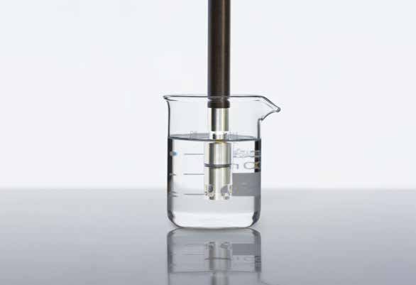
Fig. 14 Stirring attachment for
membrane would falsificate the
laboratory dissolved oxygen sen-
sors measuring result. This can be
prevented by reducing the stir-
We offer specific stirring attach- ring frequency or positioning of
ments (Fig. 14) which rotate like the sensor outside of the eddy
small turbine blades and con- formation.
stantly provide fresh samples to
21Oxygen Handbook
In the case of the installation in tion tank is non-critical due to the
pipes the sample bypasses the high sample volume. In an open
sensor head and provides suffi- beaker glass, on the other hand,
cient flow. WTW provides station- the oxygen concentration can be
ary measurement systems with easily changed through stirring.
specific mounting fixtures for
In the case of optical sensors,
pipes.
which, as a matter of principle, do
Alternatively the sensor can be not require any flow to function,
moved in the measured medium. the stirring does still help to reach
For example, stirring the sensor in the end value faster.
a beaker glass or by slewing it in
3.4.4 Salt content correction
a lake. For measurements at great
depths, armatures for measure- The temperature-dependent
ments up to 100 m are available. Bunsen coefficient (see Equation
2) changes if substances are dis-
It must be ensured that the stir- solved in the water. This effect is
ring causes no falsification of the taken into account by the input of
measured values. This may par- salinity. The salinity can be deter-
ticularly be the case if the sample mined with a conductivity meter
examined is over- or under-sat- and, to some extent, the salt
urated with oxygen and oxygen content of seawater in g/kg. This
can be expelled or stirred in. Oxy- function can be also be used for
gen over-saturation is, for exam- other waters, as the deviations are
ple, to be found in still waters in often small.
summer if the photosynthesis of
3.4.5 Impact of interferring
rampant algae produces oxygen.
gases
An example of oxygen under-sat-
The membrane of the dissolved
uration is the BOD determination
oxygen sensor can also be per-
where bacteria lower the oxygen
meated by other gases alongside
concentration by respiration in the
oxygen (Fig. 15).
Karlsruhe Bottles.
Correspondingly the sample
volume is also of importance. A
measurement in a lake or aera-
22Sensorkopf
into acidic, the measuring meter
Sensor head
displays too high readings.
CO2 N2
H2S O2 NH3
The greatest danger for dissolved
oxygen sensors comes from
hydrogen sulfide because this
H2S O2 NH3
poisons the counter electrodes
CO2 N2
through the sulfide ion created by
Fig. 15 Permeability of the mem- neutralization reaction.
brane for different gases
The sensors can cope with a small
Nitrogen is not very reactive and amount but a longer exposure
does not play any role here. will noticeably shorten the sensor
operation time. Hydrogen sulfide
The interference by ammonia is
is easily detected due to its smell,
negligible due to the high pH of
which is similar to rotten eggs and
the electrolyte.
can be noted even in the smallest
Carbon dioxide, on the other concentrations without the need
hand, is problematic. The buffer for measurement technology.
capacity of the electrolyte solution 3.4.6 Solubility function
is sufficient for short-term expo-
If the aim is to determine the
sure, but under longer-lasting ex-
concentration of the dissolved
posure carbon dioxide shifts the
oxygen in non-water-based fluids,
pH value into the aciduous range
the corresponding solubility func-
and leads to too high readings.
tion must be known. In this case,
Here galvanic sensors can regen-
the oxygen measurements are to
erate the buffer capacity better
be carried out analogous to the
than amperometric sensors, as
measurement in water.
they form excess hydroxide ions
through the electrode reactions.
In the case of high carbon dioxide
content (e.g. in beer, champagne,
lemonade), the buffer capacity
of the electrolyte solution in the
sensor is insufficient. The pH shifts
23Oxygen Handbook
SECTION 4
Optical oxygen measurement
In the past few years a further fluorescence (Fig. 16). As part of
technology has been established this, dye molecules are excited by
for dissolved oxygen measure- light. Upon return to the ground
ment. Oxygen is no longer solely state the absorbed energy is
electrochemically measured but emitted in the form of light with
also optically. [2] Of course the changed (larger) wavelengths.
basics of oxygen determination
There are substances which mea-
also remain applicable here. Cor-
surably affect this mechanism de-
responding to the measurement
pending on their concentration.
technology there are new aspects
These are the so-called quench-
which are explained below.
ers. This means that these ma-
4.1 The principle of terials absorb the energy of the
excited state so that the dye can
optical measurement
no longer emit fluorescent light
A sensor for optical measurement and is thereby “extinguished”. The
is also described as an optode. intensity of the fluorescent light
Optodes equipped with special becomes smaller the higher the
dyes show optical measurable concentration of the quencher
reactions when they come in con- molecule is. This context is basi-
tact with the specific molecules. A cally described in the Stern-Vol-
mass and energy conversion does mer Equation:
not take place as for example
with the Clark cells. It is only an I0
= 1 + k SV ⋅ c Q
energy conversion because a I
incident light beam of a certain Here I0 is the light intensity with-
wavelength is changed into light out the quencher, I the intensity
of longer wavelength and other with the quencher in a corre-
properties than the original light. sponding concentration, kSV the
This type of reaction is known as
24Stern-Volmer constant and cQ the means of this dye suitable mem-
concentration of the quencher. In branes can be produced for the
this context is also interesting that measurement of oxygen in fluids
not only the intensity but also the or gases.
temporal decay of the fluorescent
LEDs serve as the light source.
light after excitation continues to
The exciting of the fluorescence
behave correspondingly with the
takes place in a modulated man-
Stern-Volmer Equation.
ner (Fig. 17). The light emitted
from the dye in the membrane is
Green LED
Detector
detected, converted into an elec-
trical signal and converted into an
oxygen signal.
Intensity
Phase
Fig. 16 Luminescence excitation
using light of a short wavelength
Fig. 17 Simplified representation
(green here), emission of a red
of modulated stimulus and emit-
and so low-energy fluorescent
ted fluorescence beam
beam.
Green graph: light periodi-
What does this mean for the dis-
cally beamed in, red graph: light
solved oxygen measurement?
emitted from the dye at a shifted
There are dyes which are excited
phase resulting from the changed
by visible light and react on oxy-
decay ratio.
gen with a high selectivity. The
oxygen molecules serve as the
quenchers described above. They
extinguish or change the light
resulting from the dye depending
on the oxygen partial pressure. By
25Oxygen Handbook
4.2 Characteristics of optical dissolved oxygen sensor,
there is diffusion of the dissolved
the optical dissolved
oxygen in the water depending
oxygen sensors on the concentration into or out
The significant difference from of the membrane. This process
the classical dissolved oxygen naturally runs faster the better
sensors is that optical sensors the exchange takes place at the
consume no oxygen. There are interface. A stirring supports this
no electrochemical reactions. In exchange.
addition, there is a further charac-
There is no polarization time
teristic: The optical sensor does
for optical sensors as it has no
not require any flow to replace
electrodes which have to reach an
“consumed” oxygen. Stirring sys-
operating condition.
tems are then superfluous. In ad-
dition, there is no necessity for the Optical dissolved oxygen sensors
electrolyte change or cleaning the are sensors which have active
electrode system. The life span of components (LEDs, detector, pro-
the optical sensor caps with the cessor). In contrast to the electro-
dye-containing membrane usually chemical sensors, they are more
is at least one year. power consuming which leads
to a markedly reduced operating
Electrochemical sensors form in
time in the case of portable sys-
water a 10 µm thick layer of water
tems. Additionally optical sensors
molecules that can not be stirred.
need different meters.
As consequence this layer serves
as an additional diffusion barrier. The measurement range is notice-
On air these sensors show a satu- ably restricted in comparison
ration signal of about 102 %. The to the electrochemical sensors
optical sensor measures 100 % air above. The reason for this is the
saturation as this barrier does not quenching. Simplified, no oxygen
exist here. leads to a strong signal, a large
amount of oxygen leads to a weak
However it may be reasonable
signal. In general the measure-
to apply flow to an optical sen-
ment range does not exceed ap-
sor. As with all systems with
interfaces, even when using the
26prox. 200% air-saturation respec- Of course a calibration carried out
tively 20 mg/l. by the user is also possible. It is
implemented analogously to the
4.3 Calibration of optical electrochemical sensors in water-
dissolved oxygen vapor-saturated air in the calibra-
sensors tion vessel. As already mentioned
above, the resulting saturation
An advantage of the optical
display is at 100%.
dissolved oxygen sensors is
that very stable drift behaviour. 4.4 Cleaning of optical
The changes in the membrane
dissolved oxygen
are mainly caused through the
irradiated light. A decrease in sensors
sensitivity results, triggered by the The sensitive surface of an opti-
so-called bleaching to a decrease cal oxygen sensor is protected
in intensity and a change of the by a light proof top layer. This
phase shift. top layer is very thin and must
therefore not be scratched or
These changes are generally
damaged as otherwise this could
much smaller than 5% of the initial
lead to malfunctions. In relation
value over the course of a year. If
to the cleaning the same mea-
this tolerance can be accepted,
sures apply as to the conventional
the sensor does not need to be
oxygen membranes. In the case
calibrated.
of easily adhesive contamination
We apply the dye to changing careful cleaning with a soft cloth is
caps that the user simply puts recommended, further notes can
onto the sensor. These exchange be found in the operating instruc-
caps contain a chip with the tions.
specifications of the individual
membrane determined in the pro-
duction process (“factory calibra-
tion”). These data are automati-
cally transferred to the sensor and
used for the correct calculation of
the oxygen concentration.
27Oxygen Handbook
4.5 Impact of hydrogen sulfide, which results
from the putrefaction processes
interferring gases
in many waters, that here dissem-
In contrast to the amperomet- bles an oxygen signal. This signal
ric sensors, carbon dioxide and is reversible, the sensor does not
hydrogen sulfide play no role undergo any damage.
in relation to the operation life
of or damage to the sensors. It
must solely be noted that, for
example, hydrogen sulfide also
functions as a quencher due to its
molecular mass. An example from
practice would be the decreasing
oxygen content in limnological
depth measurements at increas-
ing depths, which seem to un-
dergo an increase if the sensor
is immersed into soft sediment.
However the reason for this is the
28Bibliography
[1] DIN EN ISO 5814, Water qual-
ity – Determination of dissolved
oxygen – Electrochemical probe
method, 2013
[2] DIN ISO 17289 : 2014-12
Water quality – Determination of
dissolved oxygen – Electrochemi-
cal probe method
29Oxygen Handbook
Further handbooks
Order our handbooks and
tips for practice!
• pH Handbook
• Conductivity Handbook WE SUPPLY
•
•
Ion-Selective Handbook (in preparation)
Practical
Photometry Tips KNOW
•
•
•
Titration Handbook
Viscometry Handbook
Refractometry Handbook
HOW
Meters
Lab undand ProLab
Electrodes
Titration
Titrations
pH,
Fibel Serien
Handbook
pH,ISE,
ISE,LF
LFUND
UNDOO22MESSEN
MESSEN——GENAU,
GENAU,ZUVERLÄSSIG,
ZUVERLÄSSIG,SELEKTIV
SELEKTIV
Titrations Fibel
pH, ISE, COND AND O2 | PRECISE - RELIABLE - SELECTIVE
IN LABAND
AND FIELD OFTITRATION
IN LAB AND
THEORIE
THEORY FIELD DER
UNDPRACTICE
PRAXIS TITRATION
THEORIE UND PRAXIS DER TITRATION
30About us
Information around the clock!
New products
Click here. Xylem Analytics pres-
ents you with new products, de-
velopments, innovative measure-
ment and analysis meters, helpful
accessories, useful system exten-
sions and much more.
The place to go 24 hours a day
Applications
At Xylem you will find the solution
to your measurement tasks in re-
search, analysis and quality con-
trol – and a great deal of usage tips
along with it.
Everything custom-made.
Contact addresses
Looking for a contact partner in
your area? Here you can find our
national and international contact
partners, their addresses and
representatives etc.
Simply click and browse through.
www.WTW.com
31Xylem |ˈzīləm|
1) The tissue in plants that supplies the water from the roots up through the plant;
2) a leading global water technology enterprise.
We are a global team with the shared goal of creating innovative solutions to provide for our
world’s water needs. The focus of our work is the development of new technologies that
improve the type and manner of water use and re-use in the future. We move, treat and
analyze water and lead it back into the environment, and help people to efficiently use water
in their homes, buildings, factories and agricultural operations. Through the takeover of
Sensus in October 2016, Xylem expanded its portfolio with intelligent measuring meters,
network technologies, and advanced services for data analysis in the water, gas and electric-
ity industry. We have strong long-term relationships with customers in more than 150 coun-
tries, among whom we are famed for our high-performance combination of leading product
brands and expertise, supported by a tradition of innovation.
Additional information on how Xylem can help you can be found at www.xylem.com
Xylem Analytics Asia Pacific Xylem Analytics South Asia
analytics.asia-pacific@xyleminc.com analytics.india@xyleminc.com
www.xylem-analytics.asia www.xylem-analytics.in
Xylem Analytics Australia Xylem Analytics Vietnam
salesAus@xyleminc.com analytics.vietnam@xyleminc.com
www.xylem-analytics.com.au www.xylem-analytics.vn
Xylem Analytics New Zealand Xylem Analytics Japan
analytics.nz-pacific@xyleminc.com ysijapan.support@xyleminc.com
www.xylem-analytics.com.au www.xylem-analytics.jp
© 2019 Xylem, Inc. All rights reserved.You can also read