Showerloop Kit 2019 Manual version 01 - Published April 2019 - Squarespace
←
→
Page content transcription
If your browser does not render page correctly, please read the page content below
Showerloop Kit 2019 Manual version 01 Published April 2019 Made by: Showerloop OY, Finland Written by: Jason Selvarajan, CEO Fernanda Mantilla Nikita Pavlov Online: showerloop.org/diy/manual E-mail: info@showerloop.org +358402163939 Translated versions: Translations by:

1. LINKS AND RESOURCES
showerloop.org This is website
showerloop.org/research Original bachelor's thesis’
showerloop.org/diy Instructions and design files for Showerloop
showerloop.org/store This is where you can purchase parts
showerloop.org/community Community site
on Facebook facebook.com/showerloop
on Youtube youtube.com/channel/UCaTOqjcOmjvOxqIp348tH4A
on Vimeo vimeo.com/user56408233
on Reddit www.reddit.com/r/showerloop
Fablab.aalto.fi Aalto FABLAB Digital Fabrication Laboratory.
None of this would be possible without the help of Aalto Fablab!!!!
Turbiini Startup Accelerator A startup center in Vantaa, Finland which has graciously provided us with office
space to work on Showerloop and other sustainability projects.
AIRO Island RY Our soon to be production facility is hosted by A.I. Robotics Island RY. While
Showerloop isn’t specifically in the field of A.I. we’re working with digital
fabrication tools like CNC machines and 3D printers with the goal of educating
Finns and the world about the opportunities that lie in these but amazing
technologies, especially when shared.
OSCEdays Open Source Circular Economy days 2015 in Helsinki is where we presented
Showerloop to the open source community for the first time. Jason was also one of
the organizers of the event that year and in 2016.
POC21.cc Proof of Concept 21. An innovation camp in 2015 that helped Showerloop get some
international fame.
Instructables.com https://www.instructables.com/id/Showerloop/. The POC21 prototype.
Helsinki Fashion Week This version Showerloop KIT18 was presented at the HFW2018.
GreenTech Awards We won the Gallileo Wissenpreis GreenTechAward, Berlin 2017. We also got a
business loan from the one and only Rea Garvey.
ShowerLoop KIT18 Manual 2/40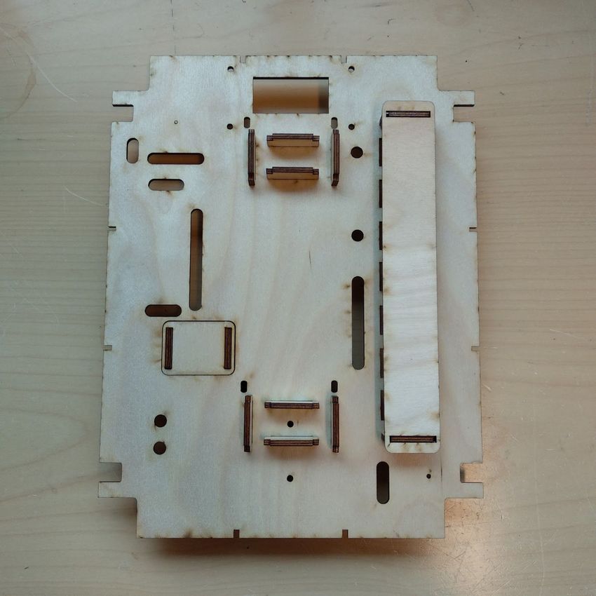
Showerloop at the Helsinki Fashion Week 2018

      ShowerLoop KIT18 Manual 3/40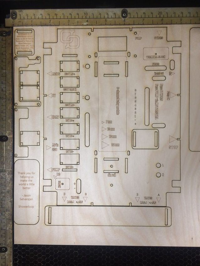
2. TABLE OF CONTENTS
1. LINKS AND RESOURCES 2
2. TABLE OF CONTENTS 4
3. SAFETY INSTRUCTIONS 6
4. BOM / COMPONENT LIST 7
Showerloop Component List 7
5. SPECIFICATIONS 7
5.1. DIMENSIONS Minimum dimensions 7
5.2. WATER CONSUMPTION 7
5.3. POWER CONSUMPTION 7
5.4. REPLACEMENT OF FILTERS & OTHERS 7
6. MATERIALS & CARE 9
6.1. THOUGHTS ON MATERIAL SELECTION, LONGEVITY AND PRODUCT LIFECYCLE 9
6.2. VERSIONS. 9
7. WHAT IS SHOWERLOOP? 11
8. OPERATING PRINCIPLE AND GENERAL SPECS 12
8.1. TAKING A LOOP SHOWER 12
8.2. MODES 12
8.2.1. Prewash 13
8.2.2. ShowerLoop 13
8.2.3. Backwash 13
8.2.4. Bypass 13
8.2.5. Pee / Flush 13
8.2.6. Drain 13
9. ASSEMBLY INSTRUCTIONS. 14
9.1. ORDER 14
9.2. SECTIONS: 14
9.2.1. Pre-filter and pump: 14
9.2.2. Valves : 14
9.2.3. Filter: 14
9.2.4. Uv: 14
10. PARTS / COMPONENTS / BOM . 15
10.1. PREFILTER. 16
10.2. PUMP. 16
10.3. Valve. 16
10.4. FILTER. 17
10.5. UV LAMP 17
10.6. HEATER. 17
10.7. PIPE FITTINGS. 17
10.7.1. Plastic quick fit hose connector. 18
10.7.2. Brass quick hose connector. 18
10.7.3. Other options. 18
10.8. ELECTRONICS . 19
10.8.1. Backboard size 30x50 plywood 3-6mm 20
10.8.2. Power Box / Relay Box 24
ShowerLoop KIT18 Manual 4/40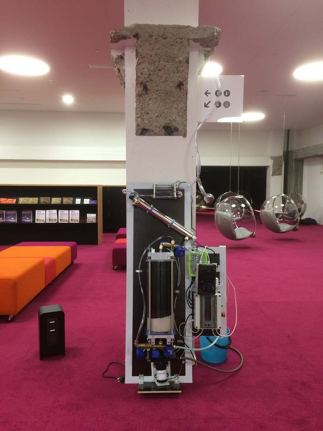
10.8.2.1. WIRING... 27
10.8.2.2. ASSEMBLY... 29
10.8.3. Switch panel / Control panel 32
10.8.3.1. WIRING & ASSEMBLY.... 34
10.8.4. Testing. 34
10.8.5. connectors / electrical fittings.. 35
10.8.5.1. JUNCTION BOXES 35
10.8.5.2. PG7 35
10.8.5.3. PG11 35
10.8.5.4. AWG/EU electrical cables 35
10.8.5.5. STANDARDS 35
11. Q&A 36
12. TROUBLESHOOTING 36
13. APPENDIX TOC 37
14. Showerloop Usage LOG. 38
15. REFERENCES, SOFTWARE & OTHER MANUALS 39
16. Link to the scanned documents here: 40
ShowerLoop KIT18 Manual 5/40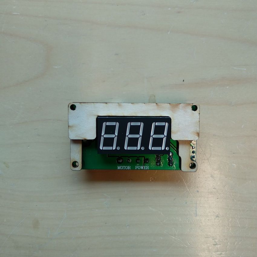
3. SAFETY INSTRUCTIONS
- READ this before using !!!
Please read these instructions carefully before using ShowerLoop. The instructions contain important information
which will help you understand the limitations of the technology and also help you get the best out of the system
and ensure safe and proper installation, use and maintenance. Keep this manual close so you can always refer to
it for j
● The filter captures particles and dirt inside it, the backwash system may help flush out these things but
the point is that it doesn’t just magically purify water with any contaminants. It was specifically designed
for use in showers.
● A short, non-looping or pre-wash is preferable before activating the loop to reduce the overall load on the
system and to remove particles, oils, and dirt from the body and therefore from entering the system
extending the life of the filtrate (filter material).
● Ultraviolet (UV) light can be dangerous. Never stare at it directly without eye protection or expose it
directly to your skin. The UV lamp has an operating time of 6000 hours (of continuous operation) before
it’s output is reduced by 20%. As a precaution, it is advised to change the lamp after 2 years or 600 hours
of operation as lamp usage is likely intermittent and the turning on and off of the lamp will reduce its
capacity sooner. Once a suitable sensor becomes available we can reliably determine the lifetime of the
lamp.
● Test the GFCI (Ground Fault Circuit Interrupter) on a monthly basis. When the system is connected to
220V AC power but not ON, Press the [T] button and everything should switch off.
● Check the cable glands, electrical boxes, and switches for leaks, holes, water moisture or anything
abnormal.
● Check the pump on a monthly basis (according to the manual) but at least open the pump and service it
each time the filter is changed (or after flushing the filter).
● Always use a pre-filter before the pump. Any debris will clog the pump and damage it. IT won’t go off
automatically and the friction can cause overheating and possibly even fire.
● Stop the pump when switching modes if possible.
● When activating the system for the first time the AC will release lots of dust and it should NOT be
recycled. Flush the system like a normal shower - clear water IN and all water to DRAIN / WASTE WATER for
5-10 minutes/ 50-100 liters. After this, the filter may release dust every now and then (especially when
tightening the filter). As long as the particles are small they will not be a problem for the filter and the
trace amounts of carbon are not dangerous if consumed.
● Don’t operate unless you are nearby (at least for the first 10 hours of operation, reset after maintenance).
● If WET, ONLY use the SWITCHBOARD and ON/OFF button on the power box.
● Attach a power consumption meter / Timer between the power plug and wall socket to measure the
operating time of the Filter.
● Log use of the system (see appendix) and report back to Showerloop Headquarters...
ShowerLoop KIT18 Manual 6/40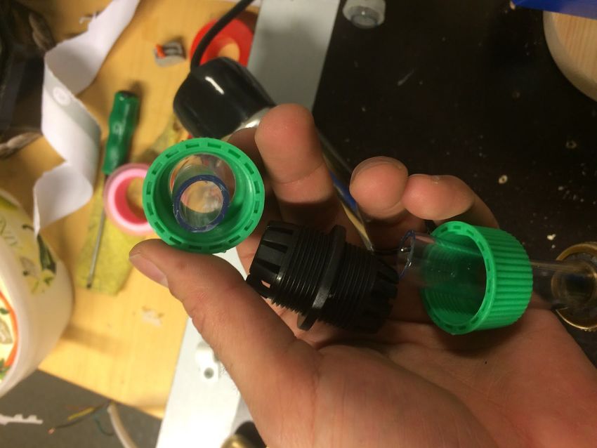
4. BOM / COMPONENT LIST
Below is a link to our component list, this includes some specifications and known suppliers. Prices may vary as
well as the products. If you’re looking for something on ebay and the link is no longer valid try searching for the
full name listed.
Showerloop Component List

5. SPECIFICATIONS
5.1. DIMENSIONS Minimum dimensions
X       WIDTH         500 mm (440 mm smallest)
Y       HEIGHT        1800 mm (1440 mm smallest)
Z       DEPTH         250 mm (230 mm smallest)
Total system weight   35 kg
Total package weight with extra parts 42 kg

XXXPICTURE OF THE WHOLE SYSTEM HERE!XXX

*** See component list for dimensions and weights of individual parts ***
*** See 3d model for design files ***

5.2. WATER CONSUMPTION
PREWASH                 1-5 L?
SHOWERLOOP              10 L
BACKWASH                0-5 L

A water and power savings calculator was developed by http://david.mercereau.info/
http://showerloopcalculator.zici.fr/en

5.3. POWER CONSUMPTION
PUMP                    40W             12VDC 8A maximum (10A fuse) 100W max. Operating power.
VALVES                  O.24W           5-24VDC 0.02A
RELAY MODULE            -               5-12VDC
SWITCHES                -               5-12VDC
AC/DC TRANSFORMER       150W            220VAC to 12VDC
UV                      30W             220VAC or 12VDC
HEATER & HEAT LOSS      3000W 14A       220VAC or

Nominal operating power is 150 W max without heating or 60 minutes is 0.150kWh
10-minute shower ~1.3 kWh
30-minute shower 2 kWh

A water and power savings calculator was developed by http://david.mercereau.info/
http://showerloopcalculator.zici.fr/en

5.4. REPLACEMENT OF FILTERS & OTHERS
SHOWER DRAIN FILTER DAILY
PREFILTER           WEEKLY - MONTHLY, INSPECTION, MONTHLY CLEANING. REPLACE AFTER 150 showers

                                          ShowerLoop KIT18 Manual 7/40
PUMP                    MONTHLY INSPECTION & CLEANING (see Pump manual)
SAND FILTER             2-5 MONTHS
AC FILTER               2-5 MONTHS
UV LAMP                 1000 hours operating time but rated for 8000 hours continuous operation               (see UV
manual)
HEATER                  6-12 MONTHS INSPECTION (see Heater manual)

Note: filter lifetime is still in need to wide scale testing. Most results are estimations based on empirical data from
our lab tests and tests with a single showerloop in household conditions. The water from Southern Finland where
the hardness of water ranges from 3.0 to 4.5 dH and water quality is good.

6. MATERIALS & CARE

6.1. THOUGHTS ON MATERIAL SELECTION, LONGEVITY AND
PRODUCT LIFECYCLE
ShowerLoop is a work in progress. Components and materials had been selected in the last 5 years (2012-2017)
carefully and under a tight budget. The limitation in resources has been the principal reason why ShowerLoop
develop process has taken longer than expected. In consequence, materials had been choose base on longevity,
price, availability and utility = sustainability. It’s likely that every component could be replaced with something
more sustainable, effective, simpler, prettier and cheaper.

Additionally, we limit the suppliers to commonly available hardware stores in Finland which have slightly smaller
selections than those in mid-Europe. ShowerLoop applies the Open Source principals, so parts can be
interchanged with what is available locally.

That said, many alternatives have been attempted with almost every component and material available, making
this last design the best of the best so far. In order to speed up the developing process, we relay in more users
fabricating/modifying their own ShowerLoops. We encourage you to find good and sustainable components, as
well as suppliers that would allow Showerloop builders to collaborate and ultimately make a super sustainable
shower.

6.2. VERSIONS.
Shower some pictures

                                          ShowerLoop KIT18 Manual 8/40
fig. 1: Showerloop assembled in Hamburg at n55 in 2016. Designed by Jason and Eduard Kobak,
  assembled by Jason and Timm Wille. Still my favorite one visually and for it’s 1m2 XYZ city
structure format, however, it doesn’t have the passive drainage possibilities of future models.

fig. 2: Showerloop at Helsinki Design Museum as part of the Enter and Encounter exhibit on the

                                  ShowerLoop KIT18 Manual 9/40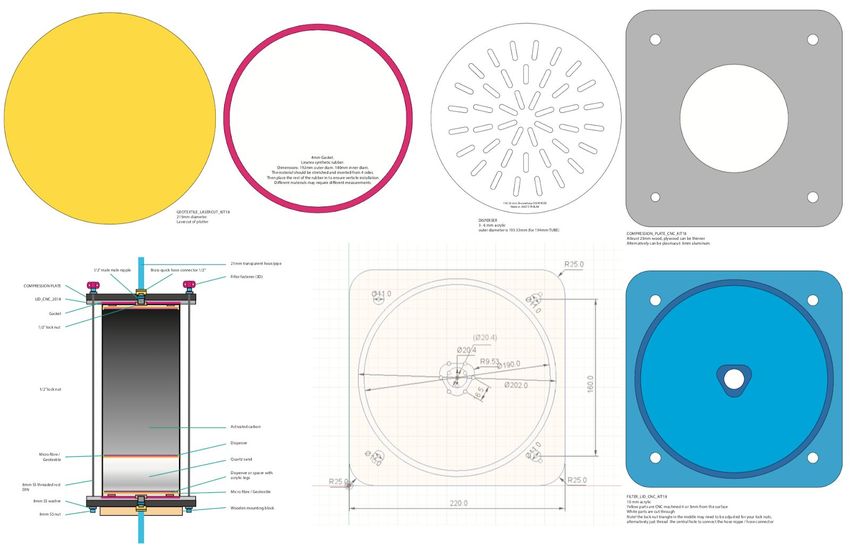
next 100 years of Finnish Design. Designed by Jason Selvarajan collaborating with Juha Kivekäs
(for the shell) using Xplision. The water flow visualization was made with the help of Niklas
Pöllönen. This version had all existing components but in a compact form.
fig. 3: Showerloop KIT exhibit at Aalto Fablab Re-Opening Event 2017, Aalto University, Espoo.
7. WHAT IS SHOWERLOOP?
Showerloop is a water filtration system made principally for Showers, allowing you to take showers at a reduced
environmental and economic cost. It requires 10 liters of water for a shower of any length* while reducing the
amount of energy needed for a nice and warm shower.
How it works is not a mystery! basically, it captures water from the drain which gets sucked through an initial
particle filter by the pump before it’s pumped through a fabric, sand and activated carbon filter to remove
particulates and organic compounds like oils and sweat. The carbon has millions of tiny pores that capture
suspended solids and can even trap molecules making the water crystal clear or pure, for the next step -
ultraviolet sterilization, to be effective.
The ultraviolet sterilization is done by The UV lamp, it emits UV-C light radiation which breaks up the DNA of
bacteria thus sterilizing it. After this, the water can be recycled/reused. Neither term is accurate as recycling is
generally more like downcycling. Reusing also is a bit incorrect as a term since the water has been upcycled from
it’s ‘dirty’ state. (returning the water as close as possible to its original form with the low-tech materials used).
Re-upclycled? UpUsed? Temperature can be maintained with a resistive heater and thermostat to automatically
maintain water temperature, though solar heating would be preferable and gas heating is a good option in some
circumstances.
The system also uses a series of electro-mechanical ball valves and piping to allow multiple shower modes:
Showerloop, bypass (which skips the filters), backwash or back-flush (to clean the filter), pee mode / direct to
drain and finally system drain - this allows all the water to be drained from the system after each shower. The
blue-grey water can also be stored and used for washing clothes or flushing the toilet. The system runs mostly on
12VDC power except for the UV and heater, though it’s possible to have a completely 12V off-grid ready system.
Still under development are 1. research on removing soaps and oils, 2. making the shower smarter using sensors,
microcontrollers and adding connectivity and programmability to the system, not to mention the 3. overall design,
usability, and production process.
Showerloop was officially started as a Bachelor's thesis project in 2012 (though proposed in class on
thermodynamics and a business competition in 2010 and). Research on filter dimensions and
purification/sterilization were the main facets of the research which can be found here:
https://www.theseus.fi/handle/10024/76148
ShowerLoop KIT18 Manual 10/408. OPERATING PRINCIPLE AND GENERAL SPECS
8.1. TAKING A LOOP SHOWER
The process of taking a shower is as follow:
❏ Check that all valves are in OFF-position (down)
❏ Check The pump is switched to zero (counterclockwise)
❏ Turn ON the system from the control box by rotating the RED ‘emergency switch’ button
❏ Set the desired heating temperature on the thermostat if it’s is available
❏ Activate the Showerloop mode on the switch panel. Normally by activating valves 2,4 and 5.
Initially, it is recommended to run the shower in ‘pee’ mode at least once before taking your first shower in order to
remove loose filter particles out of the system and not back into the filter.
Afterwards begin to fill the shower with water from your water source of choice. Hot water is preferred. Turn on the
pump on the control box (button above the stop button) and adjust the flow on the dial. stop adding water once
around 10 liters has been added to the system. You should have a continuously looping shower now. See the
troubleshooting section if things don’t look normal at this point.
Step into the shower and enjoy. When you are ready to step out of the shower and turn off the pump. Change the
mode into Backwash mode and turn the pump on again. This will pump water into the drain but backwards
through the filter rinsing it off a little.
Open all the valves but shut off all other devices since you don’t need them any longer. This will Drain the system
of excess water and prepare it for the next shower. After the whole system is drained the system can be shut down.
Keeping the system powered to allow for drainage uses a marginal amount of energy (maximum 15 W, though
likely it’s more like 1,5 W).
The system can also be drained faster by using the pump to build up a pressure in the filter. By closing the output
valve but this would require some practice as it’s a manual operating.
Getting wet and washing off main dirt particles and possibly applying shampoo. Shampoo and conditioner can
also be applied at the end of the shower if possible.
*Draining and cleaning the filter will be automatic in the next model.
a prewash or navy shower.
8.2. MODES
DIRTY WATER IN > PRE-FILTER > PUMP > VALVES > FABRIC FILTER > SAND FILTER > ACTIVATED CARBON FILTER > VALVES
> UV > HEATER > SHOWER HEAD > YOU >
There must be sufficient water in the system (7-10 liters) to fill the system.
Water is prefiltered, pumped to the filter, filtered, sterilized/purified in the UV lamp and reheated before being
looped.
fig. 4: Schematic 555
ShowerLoop KIT18 Manual 11/408.2.1. Prewash
Ideally, in this mode, you will take the initial shower before activating Showerloop mode to reduce the load on the
filters. A pre-wash or navy shower is recommended, essentially taking a really quick shower. Getting wet and
washing off main dirt particles and applying shampoo and soap.
8.2.2. ShowerLoop
: PUMP, UV, HEATER, V2, V4, V5
The main mode used to enable the filtering and reuse of shower water.
8.2.3. Backwash
: PUMP, V2, V3, V5
Run this until no water goes out the drain pipe/ the motor has run dry for a moment.
Then run Pee/Flush mode: PUMP, V2, V4
To evacuate all the water left in the system.
8.2.4. Bypass
: PUMP, V1, V2, V5
Run this until no water goes out the drain pipe/ the motor has run dry for a moment.
Then run Pee/Flush mode (see: Pee / Flush)
To evacuate all the water left in the system.
8.2.5. Pee / Flush
: PUMP, V1, V3, V4
Run this until no water goes out the drain pipe/ the motor has run dry for a moment.
Then run Pee/Flush mode: PUMP, V2, V4
To evacuate all the water left in the system.
8.2.6. Drain
: V1, V2, V3, V4, V5
This is, unfortunately, a little bit cumbersome of a process and will be automated. Leave the valves open for 10-30
minutes after you have taken a shower to allow for the filters and pipes to empty of water. For this reason, it’s good
to allow for water to drain passively from the system by connecting devices
ShowerLoop KIT18 Manual 12/409. ASSEMBLY INSTRUCTIONS.
9.1. ORDER
Figure out how you want all the components to be laid out. Lay them out on the ground or on the backboard you
intend to use.
Considerations:
The Sand/Active Carbon Filter should be upright with the current design (carbon level on the top of sand). It should
run sideways but some important features may be missing: the ability to push bubbles out of the system and
filter and passive or gravity draining. So water should always be flowing upwards or sideways (though a slight
angle is recommended).
9.2. SECTIONS:
9.2.1. Pre-filter and pump:
The pre-filter and pump intake should be aligned. It doesn’t matter if it comes from the left or right but make sure
the orientation on both the pump and the prefilter are correct. Look for the arrows showing the direction of water
flow. Ideally, both are positioned at the bottom of the Showerloop. It’s not recommended to use angled pipe
connectors with filters.
9.2.2. Valves :
Can be split into the top and bottom assemblies.
● Top Assembly: Valves I and II.
● Bottom Assembly: Valve III, IV, V.
Use 5-7 rounds of Teflon tape. This part is a little tricky because with the connectors we are using there’s no way
to ensure the orientation, except for trial and error. Using plumbing style connections (like with the POC21 version)
it’s a little easier.
9.2.3. Filter:
The main filter (sand/active carbon) should be installed in the middle of the Showerloop, preferably located over
the pump and pre-filter. The orientation of the filter is based on the internal material. The sand is located in the
bottom of the filter and the active carbon on the top of the filter. The bottom of the filter is connected to T-branch,
located between valves V3 and V4. The top of the filter is connected to the valve V2.
9.2.4. Uv:
Uv is located on top of the showerloop, over the main filter. The recommended installation angle is 45º. The lower
connector is connected to the Valve V1. The top connector is connected to the shower head.
Heater
ShowerLoop KIT18 Manual 13/4010. PARTS / COMPONENTS / BOM .
fig. 5: General assembly diagram.
List of components:
Det nr. Qty. Name Ref. number
1 1 PRE_FILTER LOOP-057
2 1 PUMP LOOP-046
3 5 VALVE LOOP-060
4 1 MAIN_FILTER LOOP-001 - LOOP-009
5 1 UV LOOP-052
6 1 CONTROLLER
ShowerLoop KIT18 Manual 14/407 1 ELECTRIC PANEL
8 3 FITTERS LOOP-022
9 10? CONNECTOR LOOP-017
10.1. PREFILTER.
The first prefilter stage is the drain itself. This is the first and best line of defense to keep
the Showerloop in working order for as long as possible. The drain will keep big size
external elements/particles out of the system.
The second stage of the Prefilter is a KIT (as shown), it contains a filter that can be
replaced when needed. An easy visual inspection will tell you whether is time to change it
(for more info check Maintenance chapter). The kit includes a support, we recommend it
for an easy installation and maintenance.
The KIT pre-filter is placed before the pump to capture large particles and prevent them
from clogging up the pump and hoses.
The prefilter should be placed horizontally with the transparent chamber facing down
and accessible so that you can clean and replace the filter.
NOTE the orientation of the filter. There should markings for IN and OUT (outside of the filter to the center and then
up and out). Also, make sure that there isn’t anything there.
Use Teflon tape or hemp fiber to seal the connections. L-bends, Male, Barbed connectors can be used.
10.2. PUMP.
The pump is a crucial part of the system, it is the device that ensures the circulation of
the water throughout all the components. There are definitely many options to choose
from, but through our experience, a self-priming water pressure pump does the job quite
well, it should cost at least 60 dollars/euros.
The Pump should be placed after the pre-filter and connect to the T-pipe located between
valve V4 and V5. This ensures a good operation of the ShowerLoop modes. It is better to
orient the motor housing facing down (as illustration ##) or horizontal so it can be
inspected and clean easily. For more information consult the self-priming water pressure
pump manual:
SEE SELF-PRIMING WATER PRESSURE PUMP MANUAL
https://docs.google.com/document/d/1uYXiMgoutgsRaZN4cyekOJQvDxBk9fcLM-2BmzSxSco/edit?usp=sharing
10.3. Valve.
The motorized ball valves are used in combination to activate the various showerloop modes by
opening and closing in specific combinations. Ball valves are nice because of their low resistance
as the diameter inside the valve is about the same as the hose in a straight line. Solenoids can also
work but they generally only flow in one direction, have high resistance, and draw much more power
(watts compared to fractions of a watt).
Valve power
On at 6.4V (very slow and weak though)
0.02A
.122 watts per valve
It goes off at 4.5V or less
0.02 A
LINK to the valve documents!!!
ShowerLoop KIT18 Manual 15/4010.4. FILTER.
fig. 6: Filter components.
Link to the design files above.
https://drive.google.com/open?id=1l7l9SxWHhkKq-GCmqPPQ-Iw2IWYjYr0T
SEE FILTER MANUAL
https://docs.google.com/document/d/1bDM_z5XQPu2OrFVX3QQyj3mfffK_Ft_fFbqZrGkTmbY/edit?usp=sharing
10.5. UV LAMP
ULTRAVIOLET IRRADIATOR
SEE UV MANUAL
10.6. HEATER.
SEE HEATER MANUAL
https://docs.google.com/document/d/1e7NSEUpV_W2SX7Yeydl1DjIKIwWVAsMepUFc0gqwdvY/edit?usp=sharing
10.7. PIPE FITTINGS.
Everything has been standardized to use 1/2” BSP (British standard pipe) threads for connecting hoses, valves,
pumps, UV, you name it. 3/8” inch might work but I haven’t used it much. Also 3/4” and 1” connections may also
ShowerLoop KIT18 Manual 16/40work better to reduce the overall pressure in the system but I have my doubts they would offer significant
improvements. 1/2” is a good size because it’s common with gardening equipment, is inexpensive and has a good
range of quality and standard parts with decent prices. Permanent fixtures with copper/ss pipe or PEX tubing will
for sure work but I haven’t been able to test them out thoroughly. Since they are an industry standard I see no
problems with them except their larger size and cost.
10.7.1. Plastic quick fit hose connector.
This is standard for connecting 2 hoses together. It’s easy to install and very reliable (no leaking) without the need
for tools as it tightening by hand is sufficient. These can be found in any gardening section in a decent hardware
store though they cost a lot compared to finds on Ebay.
fig. 7: Plastic fitting connector.
10.7.2. Brass quick hose connector.
This component took a while to find but it’s fantastic. Really should be available everywhere. It’s got the 1/2”
female thread which can also connect to a male-male connector to have both orientations.
DIAGRAMS
Brass T
Brass Male - Male
Brass Male - ½” barbed connector
10.7.3. Other options.
PEX tubing
ShowerLoop KIT18 Manual 17/40. . . copper . . .
10.8. ELECTRONICS .
COMPONENT 6 AND 7 IN THE ASSEMBLY DRAWING LIST !!!
This is technically outdated, but also a simplified version of the switchboard/power box combination. Instead of
using a relay module and trigger each device from it, the switchboard directly triggers the valves and via the
minimalistic power box on the right triggers a relay for the pump, UV, and heater. The output from the switchboard
is all 12V DC while the output from the power box is 220V AC for the UV and Heater and 12V DC for the pump. The
reason this was replaced with the Relay module is that it was both less expensive to produce at small quantities
and also provides a visual feedback for the devices. When the device is triggered via the switch a RED LED turns on
to show that the RELAY is CLOSED. Wiring the relay module is also simpler.
diagram of how the relays work
WHERE IS THE 3D MODEL?
WHERE IS THE CAM FILE?
Attachments? Links?
fig. 8: Plastic fitting connector.
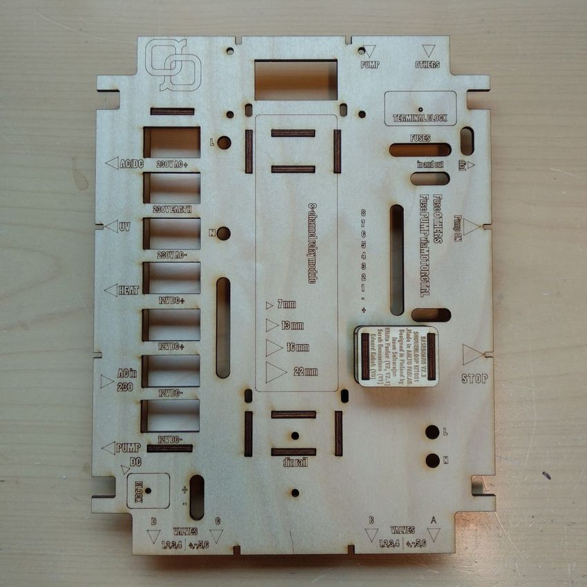
ShowerLoop KIT18 Manual 18/4010.8.1. Backboard size 30x50 plywood 3-6mm
Cut the plywood. Round the edges if desired. Lacquer or varnish.
fig. 9: Plastic fitting connector.
Laser cut baseboard for power box. Plastic may be the better option as wood will likely warp from the humidity and
changing temperatures. Hopefully, if the box leaks the wood will reveal it. Acrylic is an available alternative but
possibly less sustainable.
Complete baseboard includes 17 pieces, mainly used for organizing electronics during assembly. To help with
assembly, we have marked components’ positions on the board itself, such as position for a relay unit or cable
through-holes.
ShowerLoop KIT18 Manual 19/40fig. 10: plywood with detached pieces
For assembly, you might need wood glue and sandpaper. After cutting the plywood, gently push all the pieces out
(fig. 10) . Begin assembly with the terminal block holder. Turn the baseboard upside down, text facing down. Use two
holders to attach terminal block holder. Attach eight (8) holders in the middle of the board (fig. 12) .
ShowerLoop KIT18 Manual 20/40Fig. 11: the front end of the completed baseboard Fig. 12: backend of completed baseboard
Use two holders to attach cable organizer (marked with text) to the marked location (Fig. 11). Do not apply force,
since pieces are fragile to break.
Remove a DC-motor regulator from the protective case. Attach holders (Fig. 13) to the DC-motor regulator before
attaching regulator to the baseboard. The smaller holder is located on top of the bigger one (Fig. 14). Attach the
component to the baseboard with four M3-screws and nuts as shown in Fig. 15 and 16. Turn the baseboard around
marking text facing up.
ShowerLoop KIT18 Manual 21/40Fig. 13: DC-motor regulator holders Fig. 14: Holders pre-installed to the DC-motor regulator
Fig. 15: Installed DC-motor regulator to the baseboard Fig. 16: Installed DC-motor regulator to the baseboard
(back) (front)
Proceed with electronics’ assembling.
LASER CUTTABLE FILE
https://drive.google.com/open?id=1OIYa1M63p1VlhiQVy5KYs1pycWCMKvNk
ShowerLoop KIT18 Manual 22/4010.8.2. Power Box / Relay Box
The purpose of the power box is to house the high voltage electronics and to separate them from the user while
they are in the shower. Water and electricity can be an intimidating combination even though it’s done all the time
with washing machines, dishwashers, and jacuzzis. In Finland, we casually through streams of water at electrical
resistors while naked in the sauna.
LIST of components:
Det nr. Qty. Name Ref. number Comments
1 1 POWER BOX LOOP-028
2 1 BACKBOARD LOOP-029
3 1 RELAY MODULE LOOP-032
4 7 TERMINAL BLOCK (5 pin) LOOP-033
5 4 TERMINAL BLOCK (2 pin) LOOP-034 Use 2 x 2 pin as one 4 pin
6 1 MOTOR CONTROLLER LOOP-035 Incl. switch and control buttons
7 1 FUSE 10A LOOP-036
8 1 FUSE 1A LOOP-037
9 1 GROUND FAULT PROTECTOR LOOP-040
10 1 CIRCUIT BREAKER LOOP-041
11 1 KILLER SWITCH LOOP-113
12 11 CABLE GLAND LOOP-038 PG7, 7 x white, 4 x black
13 1 DIN RAIL LOOP-114
14 1 AC/DC CONVERTER LOOP-062
ShowerLoop KIT18 Manual 23/40fig.17: Plastic fitting connector. ShowerLoop KIT18 Manual 24/40
Begin assembly by attaching relay module (1.) to the baseboard (Fig. 18). The location for a relay module is marked
on the baseboard in the middle. The relays should be facing left towards terminal block location (Fig. 19). Secure
the relay module with four M3-screws and M3-nuts (Fig. 20). Try not to bend the relay module, as it may break.

   Fig. 18: Relay module (LOOP-032)        Fig. 19: Relay module installed    Fig. 20: Relay module installed (close)

Secure the DIN rail (13.) to the baseboard (Fig. 21). The location for a DIN rail is marked on the baseboard, located
under the relay module location. Use two M3-screws and -nuts, in addition to washers. The DIN rail should be
located directly under the relay module in addition to touching it (Fig. 22).

   Fig. 21: DIN rail with attachments         Fig. 22: DIN rail attached          Fig. 23: Cutted terminal blocks

Attach terminal blocks (5) to the baseboard (Fig. 23). Use M3 wooden screws to secure terminal blocks. The 4-pin
terminal block is used for connecting AC/DC converter to the fuses. Terminal block is located in the right-top
location of the baseboard (Fig. 24). Remaining 2-pin terminal blocks are used for DC-power connection. A 2-pin
terminal block for controlling DC-pump is located in the left-down location of the baseboard (Fig. 25). Another
2-pin terminal block is located next to the relay module and fuses (Fig. 26).

                                         ShowerLoop KIT18 Manual 25/40
Need pic.
Fig. 24: Terminal block for Fuses Fig. 25: Terminal block for DC-motor Fig. 26: Terminal block for Switch
Panel
Install Ground Fault Protector (9) and Circuit Breaker (10) to the DIN rail (13). Ground Fault Protector should be
located on top of Circuit Breaker. The 1-pole of the Ground Fault Breaker should be facing left while 2-pole should
be facing right. The Circuit Breaker should be installed such way, that the text written on both components should
be easily read without turning baseboard.
10.8.2.1. WIRING...
The process includes wiring AC and DC components. The wiring also includes adding additional components, such
as Killer Switch, Fuses, Terminal Blocks, and Pump Controller switches.
General wiring rules are included in the process, covering color pattern for AC/DC components. AC-wiring includes
usage of blue, brown and green/yellow wires, where DC-wiring includes red and black wires.
Begin with wiring AC components. Based on standard IEC 60466, phases are brown & neutral is blue. AC Power
Cable is connected to Ground Fault Protector (9.). Phases (brown) is connected to the pin 1 of Ground Fault
Protector and Neutral (blue) is connected to the N-pin on the same side. The pin 2 of Ground Fault Protector is
connected to the Circuit Breaker (10.) by the Phase (brown) wire. The wire is routed between components on the
other side of the baseboard. To secure wiring use 2.5mm2 terminal crimps (LOOP-074).
Connect the unplugged end of Circuit Breaker to the Killer Switch (11.) with Phase (brown) wire. From Killer Switch
the Phase (brown) wire is connected to the Terminal Block marked with 220 AC(+). The wire should be routed
through the back of the baseboard. The Neutral (blue) wire is routed from Ground Fault Protector’s (9.) pin N to the
Terminal Block marked with 220 AC(-). The Power Cable’s Ground is connected to the Terminal Block marked with
220 AC(grnd).
ShowerLoop KIT18 Manual 26/40Fig. 27: Fuse holders with minifuses Fig. 28: Fuse-holders installed Fig. 29: Minifuses installed
Connect Fuse Holders (Fig. 27) to the Terminal Blocks located in the top right of the baseboard. To keep Fuse
Holders secured on a baseboard, reroute wires as shown in figure 18. Install 10A Fuse (7.) to the left Fuse Holder and
1A Fuse (8.) to the right Fuse Holder (Fig. 29). On the back side of baseboard, the Fuse Holder with installed 10A
Fuse is connected to the Motor Controller (Fig. 30). The Fuse Holder with installed 1A Fuse is rerouted to the
Terminal Block marked 12V DC+ on the front side of the baseboard (Fig. 31). From previously connected Terminal
Block reroute ground wiring (black) parallel to the Fuse Holders. 10A Fuse Holder -related wire is connected to the
Motor Controller (6.) and 1A Fuse Holder -related wire is connected to the Terminal Block marked 12V DC- (Fig. 32).
Fig. 30: Fuse holders connection Fig. 31: Terminal block connection Fig. 32: DC(-) -wires connected (back)
(back)
Jump wire two 12V DC+ marked Terminal Blocks together. Connect both 12V DC+ Terminal Blocks to the Relay
Module’s(3.) COM-ports 1 … 5. Use 1.5mm2 terminal crimps (LOOP-074) to secure wiring to Relay Module. Jump wire
two 12V DC- marked Terminal Blocks together.
Connect Relay Module’s Pin DC+ to the Terminal Block marked 12V DC+, and Pin DC- to the Terminal Block marked
12V DC-. Reroute two DC wires from Motor Controller (Fig. 33) to the Terminal Block located in the lowest left side
of the baseboard marked Pump (Fig. 34).
ShowerLoop KIT18 Manual 27/40Fig. 33: DC -wiring (back) Fig. 34: Pump terminal block wired
10.8.2.2. ASSEMBLY...
Begin assembly by connecting Switch and Speed Controller to the Motor Controller (6.) Use picture [XX] as a
reference. (note: secure Switch Controller to the Power Box (1.) before connecting to the Motor Controller and use
O-ring.). Place assembled Baseboard inside the Power Box. The arrow markings should match the position of power
box’s through-holes, which indicates the correct installation position.
Attach O-rings (LOOP-039) to each Cable Gland (12.). Install and fast secure Cable Glands to the Power Box in
marked location (note: black-colored cable glands are used for AC-components, while white-colored are used for
DC-components). Don’t apply force while securing cable glands, as it may break O-rings. Secure Killer Switch to the
marked location.
Attach AC/DC Converter (14.) to the Power Box. The AC-side cable is connected appropriately to the Terminal Blocks
(AC+, AC- & GND) located on the baseboard. Two DC-side cables are connected to the terminal blocks together with
Fuse Holders: brown cable is connected with the red one and blue cable with the black one (note: you can check
the polarity of cables marked on the Converter itself).
Attach UV-light Converter to the Power Box. Cables are connected appropriately to the Terminal Blocks located on
the baseboard.
Connect 3-wire Power Plug Cable (LOOP-065) to the Power Box. Peel off protective skin to expose internal wires.
Before connecting wires, ensure that ground wire is the longest of all three wires. We recommend cutting ground
wire at least 200mm. longer than other wires. Secure wires inside the Power Box. Both phase (brown) and neutral
(blue) are connected to the Ground Fault Protector (9.) in the marked sockets. The ground is connected to the
Terminal Block marked 220 AC(grnd).
ShowerLoop KIT18 Manual 28/40fig.35: Electric Diagram. ShowerLoop KIT18 Manual 29/40
Fig. 36: Nikita made this awesome diagram for us.

WHERE IS THE 3D MODEL?
WHERE IS THE CAM FILE?
Attachments? Links?

                           ShowerLoop KIT18 Manual 30/40
10.8.3. Switch panel / Control panel
Fig. 37: control Panel diagram.
ShowerLoop KIT18 Manual 31/40Fig. 39: Switch and Control Panels.
Top left: AC/DC transformer 150W DC output. Left: Power Box, Right: Switch panel. Right, right: prototype
Showerloop mode diode module. LEFT: DIMENSIONS FOR THE 6X TOGGLE SWITCH PANEL (originally for the
Motonet/seaworld one, but also works with Biltema)
RIGHT: Dimensions for the boat rocker switch (mm). >Snug fit<
The Control Panel is pretty simple.
input is 12V DC power + and -
The switches open and close the circuit. Each switch has 3 connections,
1: +/PWR/VCC/positive
2: -/ground/negative
3: ACC/accessory/signal
There’s a common power cable for all switches and a common ground. The ACC
or signal is what’s connected to the INPUT of the relay module to power each
device.
It could be even simpler with a common ground for everything and the power
working as the signal cable and going directly to the device.
This doesn’t happen for 2 reasons. First a switch with an LED needs to have 3
connections so the power of the device isn’t going directly through the LED,
secondly, and more importantly, the switches are used to activate relays and
therefore separate the power of the device from the circuit that the user can
come into contact with while in the shower. E.g. imagine the 220V heater
connecting to the wall socket and all you have is a on/off switch to activate it. If the switch was not properly
insulated the current could pass through you and cause electric shock (this is bad). Instead now only low voltage
and low current 12V DC 0.01 A power can come into contact with the user.
ShowerLoop KIT18 Manual 32/4010.8.3.1. WIRING & ASSEMBLY....
For Control Panel the wiring and assembly simultaneously. Begin the assembly by attaching Switch Board
(LOOP-044) to the cover case of Switch Panel (LOOP-043). Remember to attach silicone gasket between switch
panel and cover case to remain IP-protectivity. Use four M3 screws and nuts to secure switch panel. Detach all
fuse holders from the switch panel.
Cut six approx. 200mm. long wires. Use a crimp tool to attach Female Spade Crimps to each cable from one side.
Connect wires by crimps to the switch panel.
Install the 8-pin terminal block inside the Switch Panel Housing (LOOP-043) and secure with the screw to the case
bottom. Attach two PG7 Cable Glands (LOOP-038) with O-rings to the holes drilled in switch panel housing.
Use two 5-meter long, 6-wires Cables (LOOP-066) to connect Power Box to the Control Panel. Peel off protective skin
(approx. 100mm. length) to expose internal wires from both sides of the cable. Connect the cable to the terminal
block located inside the Switch Panel as shown in the diagram [XX].
When all components are connected, close the case of Switch Panel and secure it properly with four screws
included with the case. Connect two previously used 6-wires Cables (LOOP-066) to the Power Box. Push cable
through two Cable Glands marked A & B. The marking on the baseboard provides you an information for each
switch controlling each valve. Using diagram [XX] as reference connect wires to the relay module and the terminal
block accordingly.
10.8.4. Testing.
Before begin testing, make sure that:
● the Emergency Stop Switch is pressed down
● both Ground Fault Protector and Circuit Breaker are switched off
● check for unplugged cables, especially attached to the AC-powered components
● make a visual inspection of all cables’ and wires’ insulation for exposed copper
● don’t touch any visible components while the electronics are powered on (!)
● don’t plug or unplug any components/cables/wires while the electronics are powered on (!)
Plug the power cord to the wall socket. Turn the Ground Fault Protector and Circuit Breaker on. Release the Killer
Switch. The Relay Module’s LED should turn on.
Test the Pump Switch, by pressing it. The LCD display should turn on and 0-value should be printed. Turn the Pump
Speed controller in both directions, while the number on LCD display should be changed between 0 … 100.
Test all switches in the Switch Panel by turning them on and off. The LEDs on Switch Panel should turn on for each
switch, while LED on Relay Board should turn on accordingly.
Test emergency shutdown by hitting Killer Switch. All LEDs should be shut down immediately. Test the
functionality of Ground Fault Protector by pressing T-button located on the component. The switch should release
immediately and the power should turn off.
End testing by pressing the Killer Switch on and unplug the power cord from the wall socket. After a little moment,
you may begin connecting Power Box to the Showerloop.
ShowerLoop KIT18 Manual 33/4010.8.5. connectors / electrical fittings..
10.8.5.1. JUNCTION BOXES
10.8.5.2. PG7
10.8.5.3. PG11
10.8.5.4. AWG/EU electrical cables
Amps
10.8.5.5. STANDARDS
AWG/EU electrical cables
IP Classifications
ShowerLoop KIT18 Manual 34/407. 11. Q&A
“... why is it necessary to discard the water after use? As in why couldn't the same water be used to shower over and
over multiple (hundreds?) of times since it's being purified with each pass?
Best, Frank
> Hey, I’m sure the water can be reused but I’m not sure how often so I don’t want to advertise it until I’ve been able
to test and verify the results, something that’s been very difficult to do since graduating from university and
losing access to the various laboratories that I had at my disposal.
The thing I’m concerned about it still water. Generally, bacteria will begin to form no matter what you do and if
there are trace nutrients in the water, which there are, biofilm would start to form on the surface layer/walls of the
storage tank. That said I think running the shower X times a day/week/month when not in use would remedy the
situation. Also, I think if it’s necessary a ceramic filter (much like a membrane filter) and or bubbling ozone
through the water would act to sterilize the water. UV would also work but we don’t have a holding tank for the
water and it’s safer/better to use various methods of sterilization to make it super safe/secure one system goes
down or isn’t sufficient to deal with some kinda superbug. Chlorine may work but only so and so since it
evaporates and would consume the Activated carbon, also I want the system to run on its own without the need for
chemicals.
The best long-term option would be solar thermal heating and desalination. Storage tanks for both hot, cold and
process or grey water. This way the system runs basically passively. All you need to do is clean the system every
now and then. Solar and batteries as storage. The point of the hot water storage is to act as a battery. Maybe a
Stirling engine or Peltier elements could work to convert some of it into electrical energy. Is there a loss when it’s
hot on one side (the hot water tank) and cold (room temp/outdoor temp) on the other side. Wouldn’t that be really
efficient? or if the efficiency is only like 20% then we’re losing 80% of the heat energy to outside. And you need a lot
of surface area. Then again maybe a container designed like a heat exchanger/heater could do everything. It would
need a way to get cleaned maybe. Maintenance would always be good - but there’s a loss in structural strength
and simplicity.... and of course, there’s always wood ovens and stuff like that.
RESOURCES
8. 12. TROUBLESHOOTING
What to do when...
ShowerLoop KIT18 Manual 35/40Everything is on but the water isn’t coming out
- Check that all devices have power.
Pumps not working
13. APPENDIX TOC
ShowerLoop KIT18 Manual 36/4014. Showerloop Usage LOG.
Date User Duration Water used Power used Notes
(minutes) (liters) (kW) Sound, smell, behavior, did it change,
what did you to do fix it
21.7 testing 5 hours? 50 flushing ? errors.
22.7 More
testing
ShowerLoop KIT18 Manual 37/4015. REFERENCES, SOFTWARE & OTHER
MANUALS
Tutorial: How to crimp connectors, strip wire and use heat shrink. Mjlorton on youtube.
https://www.youtube.com/watch?v=kjSGCSwNuAg
Common plumbing parts with names and pictures
http://www.merikarvianlvituote.fi/en/products/products/
Software we use and Open Source alternatives
Fusion360(3d models, CNC, printing)
Cura
Prusa Slicer
Tinkerkad
OpenSCAD
FreeCAD
SolveSpace
Adobe Illustrator
Gravit Designer
Inkscape
Keynote
Google Docs
Eagle (board design)
KiCAD
Easy EDA (circuit diagrams)
ShowerLoop KIT18 Manual 38/40ShowerLoop KIT18 Manual 39/40
16. Link to the scanned documents here:
MANUALS for other products
16.1. ShowerMagic : A Hygienic and Eco-Efficient Real Time Greywater Reuse System for Showers
Selvarajan, Jason; Holland, Keiran (2013)
https://www.theseus.fi/handle/10024/76148
TESTING FACILITY FOR A WATER RECYCLING SHOWER Master’s thesis
Eduard Kobak (2013)
https://dspace.cc.tut.fi/dpub/bitstream/handle/123456789/22156/Kobak.pdf?sequence=3
16.2. Testing the Efficacy of The Prototype Water Purification System for Shower Water
Mishra, Anup (2015)
https://www.theseus.fi/handle/10024/92876
16.3. Testing different combination of personal cleaning products against activated carbon for Showerloop
shower water purification system
K.C., Gaurab (2017)
https://www.theseus.fi/handle/10024/92876
ShowerLoop KIT18 Manual 40/40You can also read