Best Practices Manual for Solar Hot Water Systems - Updated: 10- 25- 2011
←
→
Page content transcription
If your browser does not render page correctly, please read the page content below
Best
Practices
Manual
for
Solar
Hot
Water
Systems
Updated:
10-‐25-‐2011
Introduction:
This manual was developed as a tool to assist solar thermal designers and
installers as a guideline to provide the most reliable solar hot-water systems
possible. The material presented here is not intended to be used as a list of
system requirements or as a type of solar code. Rather, it was assembled with
the input of many parties to share lessons learned in the field. It is not inclusive
and is a work in progress.
This manual was developed in Wisconsin where some parts of the state have
over 10,000 heating degree days and where winter temperatures regularly fall
below -30°F. In fact, the record coldest temperature recorded in Wisconsin was -
55°F. During the summer, temperatures can rise above 100°F. While most
climates are not this severe, the practices outlined in this manual will be helpful
for system designs in all cold climates as well as in warm climates.
A properly designed solar hot-water system must not only function properly
during extreme cold and hot environmental circumstances, it must also be able to
safely endure sustained periods of low or no hot water draw without damage or
overheating.
A best practice is defined as:
• A practice that is most appropriate under the circumstances.
• A technique or methodology that, through experience and research, has reliably
led to a desired or optimum result.
Overview:
A well-designed solar water heating system that is appropriate for the climate
where it is located and is properly installed with appropriate solar rated
components will last for many years. Being a mechanical system, some
components will eventually wear out and fail. The typical wear parts in a solar
water heating system include the pumps, the expansion tank, automatic valves
and the solar fluid. Environmentally, lightening can damage the controller.
Reliability studies have been conducted on solar water heating systems, but they
have been limited by the lack of data available. Despite the lack of data, certain
conclusions have been indicated. All mechanical systems follow a common
reliability path that identifies when problems typically occur. Graphically, a curve
demonstrates this where the curve is shaped like a bathtub. The following table
comes from a solar water heating reliability report created by Sandia Labs under
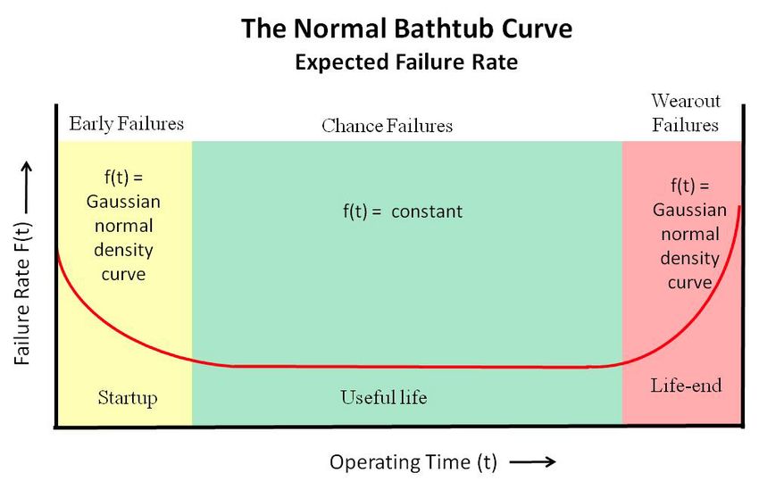
a grant from the US Department of Energy.This graph shows that the greatest probability of a failure will occur at the startup and at the end of system or component life. The failure rate early in the device’s life is characterized by startup failures due to design flaws, faulty new equipment or components, installation errors, and misuse due to ignorance (yellow area). Once these initial problems are corrected the device enters its useful operational period where failures are due to chance occurrence (green area). Later, as the device and its components age, the failures begin to increase because the system is wearing out. Failures start to slowly creep in and eventually the system fails (red area). Because most solar collectors and piping systems can last well past the average life of a pump or other shorter life components, replacing the failed component can bring a failed system back to life. This research shows the importance of post installation inspection or monitoring to overcome the potential startup failure. Solar water heating systems have a unique situation where it is difficult to notice a system failure because there is always a full-size backup water heating system in place. In a water heating system using a conventional single water heater, if the system fails there is no hot water and the owner knows it immediately and can arrange for a service call. In the case of a solar water heating system that has a backup water heater, the owner may not know if the solar water heater is not functioning because the backup water heater will provide hot water. This situation shows how critically important it is that the solar water heating system be checked periodically. Owner involvement is mandatory and the system owner must be aware of this responsibility before the installation is started. If the owner is not willing to check the system at least monthly, then the sale should not take place unless a service contract is in place or unless some type of alarm is in place that would alert the owner of a system failure. It also shows that the installer should conduct a follow-up inspection within a reasonably short period of time after the system is commissioned to identify any startup failures.
Site Assessment for all system types:
    Harnessing the sun’s energy requires proper orientation and location of the solar
    collectors to maximize system performance, efficiency and ease of installation. A site
    analysis should be performed before purchasing equipment to ensure there is
    access to the southern sky without excessive shading and available space for the
    installation of the solar collectors, solar storage and drainback tanks, pumps or
    integrated pump stations and associated piping. Steps for an effective site analysis:
    • Try to have all decision makers present during the site assessment or the sales
        call.
    • Make sure the client understands what solar hot-water systems can and cannot
        do. Many potential system owners are enthusiastic about the prospect of owning
        a solar hot-water system but may not really understand the characteristics or
        limitations of this type of investment.
    • A south facing location for the collectors is ideal. A north facing location will not
        provide adequate access to the sun’s energy and are not suitable for locating the
        solar collectors. East and west facing roof locations may be used but will require
        tilt kits to orient the collectors towards the southern sky. Web sites with satellite
        imagery (such as Google Maps) can often be used to survey the orientation of
        the roof before a site visit.
    • The best horizontal orientation is achieved when the collectors are facing due
        south plus or minus 30°, this is often referred to as the azimuth angle.
    • The best vertical orientation for year-round applications is achieved when the
        collectors are tilted at an angle equal to the geographic latitude of the location.
        Tilt kits are available to achieve the optimal vertical angle. NOTE: Customers
        often prefer to have the solar collectors flush mounted to the roof for aesthetic
        reasons. Modern solar collectors are efficient enough that flush mounting to
        pitched roofs will still provide reasonable performance for domestic water
        heating. Therefore customer’s preferences should always be considered.
    • Placing the collectors as close as possible to the peak, less 3 feet provide
        clearance for maintenance, on pitched roofs will make installation easier by
        providing increased attic access. Placing the collectors near the edge of the roof
        will make installation difficult since attic access is more restricted at this point.
        The attic space must be examined during the site analysis to confirm adequate
        space is available for installing the solar collectors in the proposed location. Be
        aware that the top 6 feet on the South side of the peak is known as the snow
        surcharge area (drifting).
    • The solar collectors should be located as close to the solar storage tank as
        possible to minimize heat loss in the piping runs, pump power and reduce
        installation cost.
    • The proposed location must have access to the southern sky with a minimum
        amount of shading between 9:00 AM and 3:00 PM each day throughout the year.
    • Determine the load:
              o Most residential clients have no idea how much hot water they actually
                   use; where feasible, meter the hot water load for a month. Otherwise, do
                   a load profile based on the ANSI/ASHRAE 90.2-2007 formula:
                       o AGPD = [CW + SPA + B](NP)
                               • Where:
                                       o AGPD = average gallons per day of hot water
                                           consumption
o CW = 2.0 gal/day per person if a clothes washer is
present in living unit, otherwise zero
o SPA = 1.25 gal/person per day additional hot water
use if a 'spa-tub is present in living unit, otherwise
zero
o B = 13.2 gal/person
o NP = number of people in living unit; if exact
information is unknown, estimate as follows, where
NSR = number of sleeping rooms:
(1.0)(NSR) for single-family detached and
manufactured (mobile) homes with one to
four sleeping rooms, plus (0.5)(NSR) for
each sleeping room beyond four, or
(1.25)(NSR) for multifamily buildings with
one to four sleeping rooms per dwelling unit,
plus (0.5)(NSR) for each sleeping room
beyond four
o Inquire whether the household may bear any behaviors or
activities that will consistently exceed or reduce the estimate
based on the ASHRAE guidance.
o Encourage the replacement of old appliances.
o Document whether loads are consistent or intermittent by inquiring
about vacation patterns or other absences in occupancy
throughout the year.
o On both residential and commercial systems, look for multiple
loads that a single system can satisfy. If possible, try to find both
winter and summer loads to satisfy so the system can provide
heat all year round.
o Do not install collectors on a bad roof.
• If shingles are nearing the end of their useful life (curling,
breaking, or significant loss of aggregate), the building should
be reroofed before the collectors are installed.
• When the site analysis is complete and it has been confirmed that the
proposed location will provide adequate access to the sun's energy and room
to install the equipment sizing and equipment selection can be made.
• Ensure the local codes regarding all mechanical components, particularly
single wall or double wall heat exchanger requirements are understood
before equipment is purchased. Order double wall heat exchanger systems if
required by local codes. Typically propylene glycol systems don’t require
double-wall heat exchanger (verify with local code official). Ethylene glycol
systems always require a double-wall heat exchanger to potable water.
• Use a site assessment tool to help determine the best place for the collectors:
o Document the solar window by taking a digital photo of the site
assessment tool or have the tool provide the picture if it has the ability.
Provide a copy to the owner and keep a copy in your files.
o Collectors can be oriented within 30 degrees of South with little difference
in output.
o Model system performance:
• When using computer modeling tools, use the following
parameters:o When shading occurs within the solar window, it is
typically the case that the site's shading occurs in
the winter months. Do not recommend a space-
heating component if that is the case. When
shading is a concern, note that while nearly all heat
is collected during the hours of 9 AM to 3 PM (solar
time), a majority of the heat is actually collected
between 10 AM to 2 PM. If this window is less than
10% shaded, it is considered a good site for a solar
water-heating system.
o Count branches of a deciduous tree at 50% shaded
during the hours impacted if the shading occurs
from October to March.
o Pay attention to future tree growth horizons.
Recommend to the owner that most types of trees
should not be planted within 50 feet of the site.
o If options are available, involve the client in deciding which sites
are acceptable for collector placement. This will prevent
misunderstandings about placement and last-minute changes to
the pump size. If the site has very limited solar access, document
the reasons for exact collector placement.
o Don’t recommend a system if the site is more than 35% shaded.
While most of the energy collected from any solar thermal system
will be in the spring, summer and fall months, you want customers
to be satisfied with their investment year-round. In case of
summer uses (i.e. cabin, pool), winter shading can be ignored.
o Document all optional pipe runs from collectors to the balance of the
system.
o If walls will be opened, document repair/carpentry costs.
o Document that there is room for the balance of the system.
o Record measurements of stairs or door openings and determine
whether they are large enough to allow tank placement.
Typical system design:
• Undersize rather than oversize:
o Size the system to provide a maximum of 100% on best solar day. This sizing
scheme results in systems that do not overheat as well as systems that have
the highest possible return on investment (ROI).
• Specify appropriate system type:
o Consider drainback systems for intermittent loads or seasonal load types, if
practical.
o Consider pressurized glycol systems for systems that have pipe runs that
cannot maintain a ¼” per foot slope back to the drainback tank and for
ground mounted systems.
• Typically, the area available for the collector array will determine the size of system,
especially in commercial applications. Another space limitation, particularly for
commercial installations, is the available room for the solar storage tanks and the
balance of system components in the mechanical room.
• If collector arrays will be in a saw tooth configuration, make sure the southern array
will not shade the northern array. Note: A little shading when the sun is at its lowest
angle will not seriously impact the performance of the system.• Systems that serve multiple loads typically have a better return on investment than
single load applications.
• Plan installation carefully so you have all components on site.
Residential system design:
• System sizing: In order to qualify for the current federal tax credit, a residential
system must be sized to cover half of the household's domestic hot water load.
This is the ideal maximum for solar hot-water systems without space or pool
heating.
• Space Heat: This option is very popular in cold climates. The collectors should be
tilted to maximize the winter sun (location latitude plus 150). To minimize
potential summer overheating, consider including a heat diversion circuit to
dissipate unwanted heat when necessary, or recommend a drainback system.
• Aesthetics: Many potential solar hot-water system owners would prefer that the
collectors be flush mounted (parallel to the roof). While this practice will have
only a small impact on the performance of the solar hot-water system in most
climates, it is important that the prospective owner be aware that in a climate that
experiences both a significant amount of annual snowfall plus experiences
prolonged below freezing temperatures, there will be a reduction in overall
system performance if the collectors are not tilted to an angle of at least 450.
Production will be lost during the winter when daily production is at it’s lowest.
• If the owner of a large house wants a solar hot-water system, but currently there
are only 1-2 occupants, system sizing will depend on the future intentions of the
owner. If the plan is to have children or to sell the home in the next few years,
size the system slightly large and consider the following:
o Tilt the collectors to the winter angle.
o Oversize the storage tank.
• Two-tank systems outperform one-tank systems in climates that experience
extended cloudy periods.
• All systems require a listed Thermostatic Mixing Valve (TMV) at the hot water
outlet of the back-up heater.
• If the back-up heater is on-demand, the TMV may be installed between the solar
storage tank and the on-demand heater. Check with the water heater
manufacturer to determine the maximum incoming water temperature allowed;
and if necessary install the TMV between the storage tank and the on-demand
heater set the TMV at or below this temperature.
• If the back-up water heater is an on-demand type, be sure that the on-demand
heater will modulate to the “off” position if the incoming preheated water is
already up to temperature.
Non-residential system design:
• Never install an automatic water fill valve on pressurized glycol systems.
• It is acceptable to use a glycol fill system (injection pump) that injects a pre-mix
of glycol into the solar loop if the pressure drops in that loop.
• Size the Heat Exchanger (HX) for a worst-case scenario with maximum possible
water temperature and solar fluid temperature). To accommodate this worst
case, the HX cannot be too big.
• Install Pressure Relief Valve (PRV) in the mechanical room:
o Pipe the PRV to within 6” of the floor.
o Locate the PRV between the collectors and any isolation valves in the
system.o Size the PRV appropriately in relation to the maximum BTU output of the
system.
Components:
• Maximum flow rates for copper tubing:
o Size the piping to maintain 5 feet of water column (head) per 100 feet of
pipe. The following graph also shows the amount of heat that can be
pushed through a pipe size at the identified flow rates and temperature
rise.
Pipe Flow Energy Delivered
Size (gpm) (BTUH @ 20°F temp
(in) rise)
½ 1.5 15,000
¾ 4 40,000
1 8 80,000
1¼ 14 140,000
1½ 22 220,000
2 47 470,000
2 1/2 85 850,000
3 130 1,300,000o Another method of pipe sizing is based on fluid velocity (between 2 and 5
feet/second) and head loss. The table below summarizes this method.
Pipe Size Flow Rate
(in) (gpm)
1/2 1–3
¾ 3–7
1 5 – 12
1¼ 8 – 19
1½ 11 – 28
2 20 – 49
2½ 31 – 76
3 44 – 110
4 78 - 296
• Sizing with a flow rate greater than 5 feet Per second (undersizing the pipe)
results in pipe erosion and requires excessive pumping energy. This is important
because it differs from the plumbing code. Closed-loop piping with pumps and
glycol is different than open-loop piping with water.
• Sizing less than 2 feet per second (oversizing the pipe) results in excessive costs
and the inability to move air through the piping (which is especially critical in
drainback systems).
• Sizing for head loss is also important because it determines the amount of
pumping energy that will be required. In space heating systems with radiant
floor/sandbed loops, or in large commercial systems, going up one pipe size can,
in some cases, save enough pumping energy to overcome the extra installation
costs in just a few years. Oversizing in the case of planning for system expansion
is justifiable. In every other case, oversizing has to be done carefully. The extra
costs may often be overlooked. It is not just additional cost in pipe, but it is also
more costly labor, fittings, and hangers. It carries over to larger insulation and
jacketing, more solar fluid, larger expansion tanks, etc. In commercial systems,
the difference is many thousands of dollars. And this is the cost that must be
offset by the benefits: savings in pumping energy and flexibility for future
expansion.
• Add parallel lines together.
• Pipes can be oversized but will increase the cost.
• 8 gpm for a 1” header means the max number of panels linked together should
be 8 to ensure 1 gpm per collector. The 8 limitation of maximum collectors linked
together is also a function of manifold expansion and contraction. This applies to
harp style absorber plate collectors. Connecting more than 8 four-foot wide
collectors can result in more expansion than the collectors can withstand without
harming the absorber plates and possibly the collector frame as well. Refer to the
collector manufacturer for specific information about this point.
• Max of 4 collectors for ¾” header.
• Long pipe runs may require expansion loops, L-bends, Z-bends or U-bends per
2008 ASHRAE HVAC systems and Equipment 45.11
• Expansion tank:
o Size this properly.
o Too big is better than too small.
o Expansion tanks cannot be oversized too large.o The expansion tank in a pressurized system must not have any isolation
valves between the tank and the collectors. If isolation valves must be
used between the expansion tank and the collectors, remove the handles
and hang them nearby.
o Specify heavy-duty tank.
o Use a solar rated tank.
o Typically set the expansion tank backpressure to 3-5 psi below system
pressure before pressurizing the system.
o Expansion tanks can be added together to handle larger systems.
o The following table offers suggested expansion tank sizing with the
following conditions: 50% propylene Glycol, 2500F maximum solar
temperature, 30-psig static pressure and a maximum 20 psig pressure
rise. This is mentioned because an expansion tank that is too small is a
common mistake in designing solar water heating system.
System Volume Tank Size
Size
Cubic (inch
Gallons Feet es) Gallons
10
5 0.67 x15 4.5
10
10 1.34 x15 4.5
10
15 2.01 x15 4.5
12.5
20 2.67 x 19 8.5
12.5
25 3.34 x 19 8.5
12.5
30 4.01 x 19 8.5
16 x
40 5.35 21 14
16 x
50 6.68 21 14
16 x
60 8.02 28 20
16 x
70 9.36 28 20
21 x
80 10.70 28 32
21 x
100 13.37 28 32
o Always use high quality solar-rated components. Solar
thermal systems may operate at higher temperature conditions
and are harder on components than hydronic heating systems.
• Glycol
o Pressure should be in the mid-range of the gauge.o Drain/fill valves should be fitted with gasketed caps to help prevent
accidental opening of the valves.
o System temperature fluctuations are much larger (-30 to +400°F) than
hydronic heating systems; leading to larger expansion tanks and
considerations for pipe expansion/contraction.
o Glycol is different than water:
o Glycol systems leak easier than water-only systems.
o It is more erosive – debur all copper tubing, use long 90-degree turns,
and leave an appropriate number of pipe diameters before and after
components.
o It has a higher coefficient of expansion – leading to larger expansion
tanks.
o It is more viscous – leading to greater head loss and larger pumps.
o It has lower heat capacity – leading to higher flow rates and larger pumps.
o It must be carefully maintained to protect vital system components.
o It should be tested for freeze protection and PH every five years or
whenever the system has encountered a prolonged no-flow situation
o Use only solar approved and rated glycol fluids
Drainback systems
o Use only type M, L, or K copper pipe; no steel, galvanized, or Pex pipe.
o Minimum pipe size is ¾” for drainback systems.
o Do not use galvanized fittings.
o Use brass or bronze fittings.
o All cast or steel components must be electronically isolated from all other
components in the system.
o Pipe must be sloped and supported by tubing hangers.
o To prevent sagging, the hangers should be spaced per MSS SP-69.
Nominal Copper
Maximum Spacing
Tube Size
(ft)
(Nominal Pipe Size)
1/2 5
3/4 5
1 6
1 1/4 7
1 1/2 8
2 8
2 1/2 9
3 10
o On any change in horizontal direction, place a hanger within one foot of
the directional change.
o On vertical runs, support the pipe at least once every ten feet.
o Install hangers that are large enough to handle the tubing insulation and
completely insulate all pipes.
o Tilt collectors per manufacturers recommendation for drainback systems.
o Size drainback tanks to hold all the liquid in the collectors and piping above
the drainback tank.
o No vents on or above drainback tanks. Drainback systems are “closed loop.”o Size the high head pump for the pipe friction and static head to the top of the
solar panels. It is always best to have the pump running as close to the
published pressure curve as possible. Err on the side of too much head when
choosing the pump. Two pumps or dual speed pumps can be used, one
dropping out or switching to a slower speed after flow has been established
using a timer or appropriate type of controller that has this function.
o Install the high head pump a minimum of two feet below the drainback tank.
o Use pipe insulation on the solar loop that is rated for a minimum continuous
temperature of 180 degrees and use pipe insulation rated to at least 250
degrees within 10 feet of the solar collectors.
o Pipe insulation on the solar loop should be at least an R-4 rating. 1” high
temperature foam insulation is generally rated at R-7 and is better.
o Do not use serpentine flat plate collectors in drainback systems.
o Do not mount harp-style flat plate collectors in the landscape position in
drainback systems
Pressurized glycol systems:
o Hang all fittings below the pipe including expansion tank(s).
o Sleeve all buried pipes.
o No galvanized pipe or fittings.
o On Photovoltaic (PV) powered systems, use proper wire size between PV
and pump or controller.
o Some installers use a glycol compatible boiler stop leak as a precautionary
practice added to the solar fluid to control micro-leaks which are sometimes
found in cast parts.
o Adequate pressure in solar loop – in cold climates, a minimum of 35psi is
generally required to keep pressure in the system when it gets below zero.
The higher the pressure, the higher the boiling point of the solar fluid. Make
sure the back-pressure of the expansion tank is set accordingly (3#-5# below
system pressure @ 600 F)
o If corrugated piping is used, be sure to consider the friction head of the pipe.
Corrugated piping has a high pressure drop/friction head.
o For large systems with lots of exterior piping in cold climates, install a heat
exchanger bypass to stop potential heat exchanger freezing.
o In freezing weather ,cold solar fluid can freeze the heat
exchanger on system start-up.
o Bypass consists of an aquastat that measures incoming solar
fluid temperature. If below 35°F, the aquastat engages a
motorized valve which diverts the solar fluid back to the
collector array.
o If using a swing check valve, locate the valve properly.
o There should only be one check valve on the solar loop of a pressurized
glycol system. If using a spring check valve, insure it is the low resistance
type.
o Because all pressurized systems have the potential to “steam-back”, it is
considered a best practice to install the check valve on the return piping
(going back to the collector) and to locate the expansion tank above the
check valve. When a system goes into “steam-back”, steam forms inside the
collector and pushes any remaining fluid down through the return line and
ending up in the expansion tank. Therefore the expansion tank must not be
isolated from the collector on the return line (flow to the collector).o Isolate the air vent located at the top of the piping with a ball valve and close
after one month of operation. Make sure the automatic air vent is solar rated.
o Use ball valve-type valves for fill and drain valves and cap with gasketed cap.
Be aware of a potential problem with using ball valves on the solar loop. The
potential problem is that many ball valves capture a small amount of liquid
within the valve body. When the valve is exposed to elevated temperatures,
the captured liquid will expand and may damage the plastic seal resulting in a
leaky valve. Solar rated ball valves generally are made to eliminate this
problem.
o Use pipe insulation on the solar loop between the collector array and the heat
exchanger that is rated to at least 250°F continuous. 180 degree-rated pipe
insulation is adequate on the solar loop piping from the heat exchanger back
to the collector array.
o Use only closed cell foam pipe insulation on all exterior pipes, including all
buried pipes.
o All buried pipes should be placed inside a sleeve or chase and never direct
buried. The chase will allow for expansion and contraction of the pipe and
help eliminate pipe failure.
o Route sensor wire inside a pipe jacket or within a dedicated conduit where it
will not be exposed to the elements.
Installation – Roof:
• Every roof structure that solar collectors will be mounted on must be carefully
inspected for structural integrity. Depending on your location, many permitting
authorities will require an in-depth description and possibly an accurate analysis
of the load carrying capacity of a roof where solar collectors will be mounted.
o All non-residential buildings over 50,000 cubic feet that will have solar
collectors mounted on them will require a set of approved plans in order
to receive a building permit.
o Document the construction of the roof. Most municipalities will require
structural information about buildings where solar collectors will be
mounted on them in order to receive a building permit. The more
information you can collect about the structure of the building will help
facilitate this process. Some municipalities will require calculations to
show that the weight loading of the solar collector array will not adversely
affect the building structure. At a minimum, the following information
about the building will be needed:
o Size of framing members (2x4, 2x6, etc.).
o Measure all spans (span of roof members) as well as the width,
depth, and height of the building.
o Document if the roof structure uses trusses or rafters. For trusses,
measure and draw a diagram that includes where all truss
members and plates are located. For rafters, identify if there are
any braces or beams.
o On the roof drawing, specify exactly where the solar collectors will
be located. Include exact locations of all anchor points.
o If using trusses, get a copy of the truss manufacturer’s
specification sheet if possible.
o Document if and where there are any chimneys, skylights, or
dormers on the roof structure.o Take photos of the roof structure if accessible (both exterior and
interior).
o Document the type and dimensions of the roof sheathing.
o Document type and number of layers of shingles and felt.
o For steel or tiled roofing materials, document the weight of those
materials (pounds per square foot).
• Spread the load over a large area as this reduces point loads on the roof.
o If the collectors will be mounted on a rail system (recommended), attach
the rails to every rafter or truss to distribute the load evenly on the
maximum number of framing members.
• Use spanner mounting hardware if available or lag bolts as specified by a
structural engineer or approved by the local building authority to secure the solar
collectors to the roof.
• When using lag bolts lag into the exact center of the framing member.
• Always use the recommended size and type of lag bolt.
• Ensure each penetration through roof made for the collector mounting hardware
is properly flashed in accordance with local building codes.
• Ensure each penetration through the roof made for solar loop piping is properly
flashed in accordance with local building codes.
• Use roofing grade caulk that stays flexible forever, that never dries out and sticks
to wood, shingles and metal.
• Do not locate relief valves on the roof.
• Only used closed-cell, foam, high temperature pipe insulation above the roof.
• Mineral wool or fiberglass pipe insulation may provide fire protection where the
piping passes through a firestop.
• Jacket all exposed piping.
• Use stainless steel fasteners.
• Use solid brass unions between collectors.
• Do not install collectors on a bad roof.
o If shingles are nearing the end of their useful life (curling, breaking, or
significant loss of aggregate), the building should be reroofed before the
collectors are installed.
Installation – Awning Mount:
• Where the collector array is hung on a wall, the wall must be strong enough to
hold the weight of the collectors and racking.
o Distribute the weight over as many building framing members as possible.
Unistrut-type racking bolted to the framing members can distribute the
weight evenly on the wall.
o Do not just bolt/screw fasteners into the sheathing alone, bolt/screw into
the framing members of the wall.
o If the wall has a brick veneer, the racking must pass through the veneer
to the wall framing members behind the brick.
• Most flat plate collectors cannot be hung from the top rail of the collector because
the collector was not designed to be mounted in this way.
o To strengthen a flat plate collector so it can be hung from its top rail,
install two pieces of aluminum angle iron connecting the top rail to the
bottom rail, spaced one foot in from each side. This will hold the collector
together.o Another method is to install a rack to the wall and then flush mount the
collectors to the rack.
Installation - General
• Use water-soluble flux.
• Rinse solar loop with hot water with boiler cleaner added, then follow with a cold-
water rinse before filling solar loop with solar fluid. This will clean out any dirt, oils
and flux residues.
• Use only “Solar Rated” Propylene Glycol. The temperature rating should be at
least 320°F continuous.
• Check glycol with refractometer after filling to ensure proper freeze protection.
• Dilute glycol with distilled or de-mineralized water only.
• If using a water-only drainback, use distilled or de-mineralized water as the solar
fluid.
• Do not use di-electric unions on stainless steel storage tanks.
• If piping travels down the side of a house, consider using vinyl two-piece chase.
• Properly seal rim joist penetrations.
Installation – Controller:
• Collectors and solar loop piping must be properly grounded as per NFPA 780
(national standard for lightening protection systems)
• Use proper size and type of sensor wire.
o Use jacket sensor wire that is rated for outdoor use
o Required: twisted wire (#18 minimum) with a shielded cable.
o Only attach shield to ground lug in controller and trim other end of shield.
• Use watertight connectors or solder connections. Corroded sensor wire splices
are a common problem that can be easily remedied.
o Utilize a telecommunications splice as an option.
• Installation – Sensors:
o Use heavy-duty high temperature-rated sensors.
o The best location for the collector sensor is on top of the upper collector
manifold, preferably inside the collector.
o If sensor is clamped outside of the collector, insulate very well.
o Where feasible, use immersion wells instead of clamping methods.
o Use heat transfer grease on all sensors.
o Securely clamp sensor to collector and/or tank.
• Installation – Heat Exchanger:
o Install isolation valves and drain/fill ports on the waterside of the heat
exchanger to facilitate cleaning, especially if the heat exchanger is the
plate type. Remove the handles on the isolation valves so they will not
inadvertently be closed. Hang the handles nearby.
o Insulate heat exchanger well.
o Label the heat exchanger (single or double wall).
Installation – Potable Side of System:
• Use a domestic water thermal expansion tank where there is a backflow
preventer on the cold-water inlet. Common applications are commercial
buildings and well systems (often the well tank is not sized to accommodate extraexpansion, especially in large systems). Place the expansion tank so there is not
a check valve between the storage tanks and the expansion tank.
• DHW recirculation systems
o There are as many domestic hot water recirculation systems as there are
buildings. There is no specific recommended DHW recirculation system
recommended for use when a solar water heating system is present. It is
important that if there is a DHW recirculation system present that certain
precautions be observed. The following are some concepts to keep in
mind:
o Route the recirculation return so it 1) bypasses the solar storage
tank and returns to the backup water heater, or 2) can be diverted
to either the solar storage tank (when it is warmer than the
recirculating return) or the backup water heater using automatic
controls. Routing the recirculating return to go through the solar
storage tanks all of the time sets a minimum tank temperature of
at least 100°F, thereby increasing standby losses and decreasing
solar contribution.
• Install a check valve on the cold-water inlet to the thermostatic mixing valve to
reduce thermosiphoning of heat up the cold-water inlet.
• Check valves may be necessary on other ports of the thermostatic mixing valve if
the system has recirculation present.
• In cases where the mixing valve is set to a lower temperature than the backup
water heater, the DHW recirculation return should branch through the backup
water heater and the thermostatic mixing valve.
• DHW Recirculation systems should not be used with one-tank systems.
Indoor Swimming Pool Heating Systems:
• Cuprous-Nickel or marine-grade stainless steel (the stainless steel is longer
lasting) heat exchangers are required wherever chlorinated pool water may
contact the heat exchanger. For salt-water pools a titanium heat exchanger is
required. All piping on the pool waterside of the heat exchanger should be
plastic.
• When sizing a solar pool heating system for indoor pools, it is considered a best
practice to size the collector array to heat the pool 100% on the best solar day of
the year and also to tilt the collectors to an angle equal to the latitude of the
location plus 15 degrees. This sizing method will maximize the return on
investment and minimize any potential overheating during the warm part of the
year.
• The deployment of a seasonal pool heating system on a year-round pool may
offer a lower up-front cost, but in return the system provides lower annual energy
savings and requires regular and strict adherence to a maintenance schedule
(de-commissioning in the Fall and re-commissioning in late Spring).
Commissioning:
• Labeling – label major system components.
o Also label solar loop piping (identify pipes with direction of flow).
• Heat Exchanger – label stating single or double wall.
• Glycol label should include:
o Glycol Manufacturer
o Date of fill
o Concentrationo Refractometer reading
o System volume
• Owners Manual should contain:
o Date of installation
o System diagram
o System verbal description
o Maintenance information, monthly, annually
o Component warranty information
o Glycol information
o Installation and service contractor contact information
You can also read