Sail-Gen Water Powered Generator Users Manual
←
→
Page content transcription
If your browser does not render page correctly, please read the page content below
Sail-Gen Water Powered Generator
                                     Users Manual

Eclectic Energy Limited
Unit 22
Sherwood Networkcentre
Sherwood Energy Village
Ollerton, Nottinghamshire
NG22 9FD
United Kingdom
Telephone: +44 (0)1623 835400 Facsimile: +44 (0)1623 860617
Web: www.eclectic-energy.co.uk Email: sales@eclectic-energy.co.uk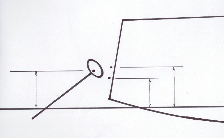
Contents                                                                      Page
Safety
                               Installation                                     3
                               General Handling                                 3
                               Electrical Hazard                                3
                               Man Over Board                                   3
Renewables On Board
                               Advantages Of Water Generation                   4
                               Sail-Gen Features And Performance               4/5
Sail-Gen Operation
                               Sail-Gen Variants And Installation Options       6
                               Assembly                                        6/7
                               Sail-Gen Positioning Considerations              8
                               Avoid Water Turbulence                           8
                               Installing On Mono Hulls                         9
                               Installing On Multi Hulls                        9
                               Installing With Davits                           9
Sail-Gen Mount Options
                               Mounting Hardware                            9/10/11/12
Electrical Installation        Wire Sizing                                  13/14/15

Charge Regulation                                                              16

Deploying Sail-Gen
                               Recovering And Stowing Sail-Gen                17/18
                               Correct Use Of The Recovery Lanyard             19
                               Adjusting The Dive Plane                        20
Maintenance                                                                   20/21
System Monitoring
                               Log Calibration                                 21
                               Battery Monitoring                              21

Performance And Expectations                                                   21
                               Power Curve                                     22
Specifications                                                                 23

Troubleshooting / Spares
                               Troubleshooting                                 24
                               Spares                                          24
Warranty                                                                       25

                                         2
WELCOME TO SAIL-GEN!

Congratulations on your choice of the Sail-Gen water generator from Eclectic Energy.
Sail-Gen is capable of producing sufficient electricity to offset most or all of the power used by the typical cruising
yacht on passage. This adds greatly to comfort and security on board and frees the owner from running the main
engine or generator on a daily basis in order to charge batteries.

Safety Issues

As with all electrical and mechanical equipment, precautions should be taken when handling, installing and
operating the Sail-Gen water generator. We advise that you familiarise yourself with the product manual and the
safety information it contains. In particular do not underestimate the weight and size of the unit when installing or
removing the Sail-Gen from the yacht. Never try to slow or stop the water impeller or drive shaft with your hands.

Installation

When installing the Sail-Gen, due care should be exercised at all times. The Sail-Gen weighs 17.6kg and is awkward in
shape with the weight concentrated at one end. It is sensible to approach installation in a methodical manner and to
enlist some help when attaching or removing the machine from the transom.

If possible, install the Sail-Gen when the yacht is ashore. If this not practicable, installing in a marina with the yacht
secured stern to a pontoon is a good alternative. The pontoon provides a safe and convenient working platform.
A dinghy can be lashed across the transom in order to provide additional security, if work has to be done at anchor.

General Handling

The Sail-Gen alternator, yoke and ‘c‘ bracket mountings incorporate pivots to allow freedom of movement both
vertically and horizontally. Although designed with generous clearances, care should be taken to avoid trapping
hands and fingers when handling the Sail-Gen.

The Sail-Gen is a very robustly engineered product. However the alternator contains high energy ferrite magnetic
rotors. Ferrite is a brittle material that can suffer damage if the alternator is dropped or handled heavily.

Electrical Hazards

When operating, the Sail-Gen is capable of producing high voltages, particularly if disconnected from the batteries.
Caution should be exercised at all times to avoid electric shock.

Always observe correct polarity when connecting the Sail-Gen to the regulator and the batteries. Reverse polarity
connection will result in damage to the water generator.

The Sail-Gen must be appropriately fused at all times.

Connecting cables must be of a suitable gauge and rating. Disconnect at the batteries before attempting
maintenance.

Dump resistors associated with charge regulators can become very hot once the batteries are full. Avoid touching
these resistors and do not restrict the airflow around them with clothing, sail bags or similar.

Man Overboard

The Sail-Gen should be recovered immediately if people are in the water. The spinning water impeller can cause
serious injury.

                                                             3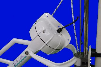
Renewable Power on Board
The Advantages of Water Generation
Generating electrical power is a constant preoccupation for yachtsman. Many choose to address this by installing
renewable energy devices such as photovoltaic panels or wind generators. These technologies can make a valuable
contribution to the yacht’s power needs.
However both wind and PV work at their best when the yacht is at anchor. On passage with sails deployed, PV
panels are often shaded or angled away from the sun. Also PV panels do not work at night!
Wind generators require a fast and uniform wind flow to work optimally, and there is a cubic relationship between
the wind velocity and the energy it contains. This means that at low wind speeds there is very little energy available.
Most long passages under sail are made downwind. On this point of sail the wind passing over the deck is effectively
reduced by the boat speed.
The yacht’s motion in a seaway also produces gyroscopic forces which act on the wind turbine’s rotating parts. This
affects yaw stability and the ability of the turbine to accurately track the wind.
All of these factors combine to reduce wind generator output when a yacht is on passage.
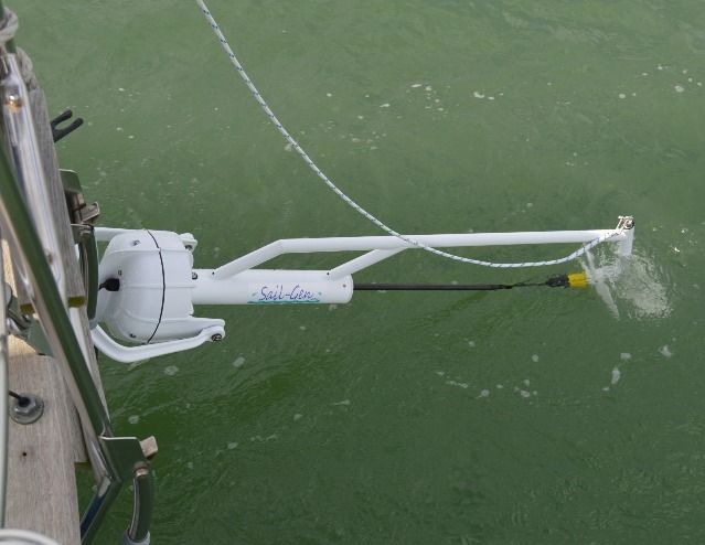
By contrast water generation works superbly on passage!
Features and performance of the Sail-Gen
The Sail-Gen is a dedicated, water powered generator for cruising yachts designed specifically to maximise electricity
production whilst on passage.
At typical passage speeds of 5-6 knots the Sail-Gen’s output is usually sufficient to balance the power consumed, i.e.
150-200 amp hours per day. Larger yachts which achieve higher average passage speeds in the 7-8 knot range can
expect yields from the Sail-Gen of 300-400 amp hours per day.
The Sail-Gen water generator converts into elecricity a proportion of the wind energy captured by the yacht’s whole
sail plan . It does this by extracting energy from the boat’s motion through the water.
One obvious advantage is that the yacht’s sail plan intercepts a much greater area of wind flow than a dedicated
wind turbine ever could. Also, water is 800 times denser than air, so a small impeller is all that is required to extract
a lot of energy from the water
The inertia provided by the yacht’s hull evens out the fluctuations in power output typically seen in wind generators.
The result is continuous, consistent power production as long as the yacht is underway. Water generation is also
quiet and vibration-free.
Water generators for yachts are of three main types: tow rope machines where a heavy impeller is pulled on a 100
foot line, submersible ‘outboard leg’ type generators, and finally the Eclectic concept characterised by a hydro-
dynamic foil to control impeller running depth.
There are many discrete advantages offered by the Eclectic approach.
The Sail-Gen can be installed satisfactorily alongside self-steering systems. Allowing 400 –500mm of lateral spacing
between the equipment usually ensures there is no chance of contact between the steering’s servo arm and the Sail-
Gen.
4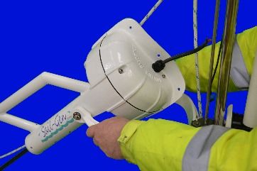
Unlike tow-rope type water generation systems, the Sail-Gen is truly practical in use and can be deployed and
recovered in seconds and with little effort. As the Sail-Gen operates in a controlled way with the impeller close to
the transom, drag is minimised and it is possible to trawl fishing lines when on passage with minimal risk of a tangle.

Outboard leg type water generators are only free to pivot laterally whereas the Sail-Gen’s mounting is fully
gimballed, allowing both vertical and lateral movement. Sail-Gen’s dive plane acts to prevent the impeller either
surfacing or sinking, and allows the impeller to ‘fly’ through the waves, independent of the vertical motion of the
yacht’s transom as she pitches.

Loss of boat speed is kept to a minimum by the Sail-Gen’s efficient impeller and low drag design. The adjustable
diving plane controls the impeller operating depth and minimises wetted area. Typically, boat speed losses are one
tenth of a knot or less.

Water generators that take the form of an outboard motor leg cannot damp out the vertical component of the
yacht’s motion. This means the water flow seen by the water impeller continually varies and does not remain
perpendicular to the impeller plane. These units are free to pivot laterally and as a result have a tendency to yaw to
one side as a torque reaction to the rotating impeller. The Sail-Gen’s design avoids both of these problems, and
ensures the water impeller is presented optimally to the water flow more of the time, increasing efficiency and
reducing drag.

In the unfortunate event of collision with floating debris, the Sail-Gen is free to pivot upwards, reducing the impact.
For high speed craft the results of impact can be servere damage. It is possible to rig a collison pull rod between the
Sail-Gen alternator and dive plane. The collision pull rod offers physcal protection for Sail-Gen’s drive shaft and
impeller. Any floating obstruction is likely to strike the pull rod first. The pull rod transfers this force to the dive plane
which will move to its maximum negative angle of attack. This causes Sail-Gen to fly upwards out the water,
decreasing the chances of serous damage. A fixed ‘outboard leg’ type unit relies on a mechanical ‘fuse’ in the hold-
down line to break on impact and mitigate damage.

Finally, with the Sail-Gen, the alternator and electrical connections are placed 500mm above the yacht’s water line.
With other types of water generator, the alternator is submerged. The serviceability of such units is then wholly
reliant on the integrity of the shaft seal to keep the sea water out of the alternator.

                                                              5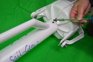
Sail-Gen Variants and Installation Options

For optimum performance it is important that Sail-Gen is competently installed in line with the recommendations
contained in this guide.

The Sail-Gen is supplied complete with standard mount hardware. In most cases this will be sufficient to achieve an
excellent installation. However, yachts differ widely in form and size, and in some cases additional brackets or
packing pieces may be required.

Eclectic Energy can offer advice and suggestions on installation. A photograph or dimensioned sketch of the transom
of your yacht will be useful to evaluate mount options.

Note that Sail-Gen is available in 12 and 24 volt versions. There is also a choice of water impeller dependent on the
potential speed of the vessel. The ‘standard’ 290mm diameter impeller is recommended for yachts capable of a
maximum sustained speed of nine knots or less. The 240mm diameter ‘High-Speed’ impeller allows for sustained
boat speeds up to fifteen knots. Ensure the correct voltage/impeller combination has been ordered for your yacht.

               Standard Impeller and large dive plane           High Speed Impeller small dive

Assembling Sail-Gen

For ease of handling, your Sail-Gen is supplied in three cartons, and requires preliminary assembly before
installation on the yacht.

One carton contains the alternator, the second the main frame and drive shafts, the third contains the water
impeller, dive plane and mount sundries.

Unless you have access to a large workbench, we suggest you undertake the assembly on the floor, as the completed
machine will be around 1.4 metres long.

Avoid assembling on a pontoon or a sloping deck as dropped fasteners can easily find their way into the water!

1. Unpack the box marked ‘Alternator’. Check the identification label on the back to ensure the alternator is the
   correct voltage for your yacht’s system. Also, take a note of the alternator’s serial number and enter it into the
   instruction manual for future reference.
2. Open the second carton and remove the main frame and drive shaft assembly.
3. Arrange the alternator such that the shaft is aligned with the tower tube and driveshaft. Pull the outer part of
   the telescopic drive shaft out of the bottom of the tower tube. This exposes the shaft coupler.

                                                           6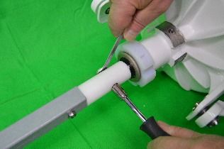
4. Remove the lower M6 nut and bolt from the shaft coupler and then slide the coupler onto the alternator drive
   shaft. Align the holes through the coupler and alternator shaft, and re-fit the M6 bolt and nut.

5. Remove the two M8 tower cap screws and plastic washers from the base of the alternator nose. Apply Tef-Gel
   anti-seize compound to the machined aluminium surface at the base of the alternator nose. This will prevent
   corrosion and ease subsequent disassembly. Also, apply a little Tef-Gel to the tapped M8 holes.

6. Slide the tower tube onto the alternator nose. Note that as you do so the upper drive shaft sleeve needs to pass
   through the spherical bearing at the top of the tower tube. If the tower will not slide all the way onto the
   alternator nose, check the alignment of this bearing and get an assistant to ‘wobble’ the upper drive shaft to get
   it to enter the top bearing. Do not force it.
7. Align the alternator such that the cable gland is on the right hand side when viewed from the rear. Rotate the
   tower tube and frame such that the lifting eye is uppermost.

    Refit the two M8 tower cap screws and plastic washers, having first smeared the threads with a little Tef-Gel.

8. Rotate the black conical connector on the upper drive shaft to ensure that the drive shafts rotate smoothly.
   Should the drive shaft bind, suspect the coupler installation, and re-check for the correct fitting of the coupler
   bolt.

9. Using the M10 pivot pins, washers and split pins provided, attach the alternator yoke to the alternator lugs.
   Take care to orientate the yoke correctly depending on whether the yoke needs to cant up or droop down to
   facilitate the installation.

10. Fit the dive plane to the frame beneath the impeller, using the supplied M5 shoulder bolt. Do not over tighten
    this bolt. The dive plane should pivot freely.

                                                           7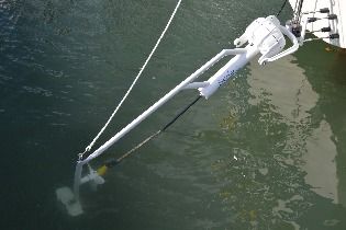
Sail-Gen positioning considerations

The Sail-Gen uses Eclectic’s unique and proven approach to water generation where the water impeller depth is
controlled by a hydro-foil we refer to as a ‘dive plane’.

In order to provide the correct geometry which enables Sail-Gen to operate optimally, it is preferable to mount the
Sail-Gen as close to a mono hull’s centre line as possible. This minimises the difference in the running depth of the
water impeller from tack to tack. On most yachts, it is both impractical and undesirable to mount directly on the
centre line, but if the installation is made within 500mm either side of the centre, the Sail-Gen will perform
optimally. Where the installation needs to be made further outboard, the Sail-Gen will still work well, but there will
be a greater difference in the running depth of the water impeller from tack to tack. This will result in higher
outputs, but also higher drag on one tack and the reverse condition on the opposite tack.

The Sail-Gen mounting consists of a yoke and a ‘c’ bracket which allows for two degrees of freedom – the Sail-Gen is
free to pivot both laterally and vertically to allow for steering and wave action. The cast aluminium yoke which
supports the alternator is reversible. It can be fitted with the yoke arms either canted upwards, or drooping down.
Given that the alternator pivot point is required to be 500mm above the static water line, this means the underside
of the ‘c’ bracket can be attached at the yacht at either 400mm or 540mm above the water line, depending on which
option is most practical.

                                  Tilt up                                     Tilt down

 The owner should be aware that this hinging creates a potential trap hazard for hands and fingers. The Sail-Gen is
provided with generous clearances between yoke and alternator in order to minimise the risk of accidental crush
injuries. However, hands should not be placed on the alternator or yoke when the Sail-Gen is operating.

                                                                    !
                                                               Do not place hands here

Water Turbulence

When considering the best mount position for the Sail-Gen on avoid making the installation directly in line with a
central rudder or skeg. Any obstruction ahead of the Sail-Gen impeller will introduce turbulence into the water flow
and this will reduce the Sail-Gen’s efficiency and output.
The same advice applies where a yacht has twin rudders placed to port and starboard

                                                           8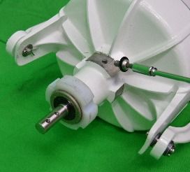
Installing Sail-Gen on Mono-hulls

Wherever possible Sail-Gen should be positioned in accordance with the dimensions recommended. If the
installation has to be made slightly further out board Sail-Gen will still work acceptably well, particularly at the
modest heel angles associated with trade wind sailing. However if the only viable mount position is right out at the
yachts quarter then the best solution may be to install two Sail-Gen and deploy the leeward unit selectively whilst
recovering the windward.

   Central rudder starboard          Central rudder part        Twin rudders central      Central rudder
                                        installation                installation     adjustable height twin
                                                                                      Sail-Gens installation

Installing Sail-Gen on Multi-hulls

As multi-hulls do not heel to the same extent as mono hulls the mount position for Sail-Gen is less critical. Usually
installations are made off the bridge deck. Note that Sail-Gen must be mounted at least 700mm inboard from either
hull to provide the clearance necessary for the unit to pivot laterally in response to steering and wave action.

                                             6-700mm
Davits

Where a yacht is fitted with davits and a dinghy is carried, Sail-Gen can often be installed beneath. It is sometimes
possible to mount off the blocks at the transom to which the davit is attached. A recovery line can be run through a
small block and cam cleat which enables the Sail-Gen to be ‘parked’ in a horizontal position under the dinghy or arm
of the davit. With some minor modification it is also possible to stow the Sail-Gen across the transom, below the
bottom of the dinghy.

Sail-Gen Mounting Options

Also refer to information contained in the eletrical installations section:

1) The Sail-Gen alternator is supported by a cast aluminium yoke and secured via 10 mm stainless steel pins which
pass through plastic bearing bushes in both yoke and alternator lugs. This provides for the Sail-Gen’s freedom of
movement on the vertical axis.
The yoke is in turn attached to an anodised aluminium ‘C’ bracket with a 10 mm stainless steel pivot pin. This pin
passes through plastic bearing bushes in both the ‘C’ bracket and the central boss of the yoke. This allows for
freedom of movement on the horizonal axis.

2) The ‘C’ bracket is used to attach the Sail-Gen to the yacht. Where possible, installation should be made within 500
mm of the yachts centre line.
The lower edge of the ‘C’ bracket should be attached such that it is either 400 or 540 mm above the static water line.
The architecture of the yacht will suggest which is the best option.

                                                            9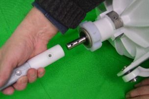
If the lower ‘C’ bracket position offers the most practical mount solution, the yoke is subsequently fitted in its ‘tilt
up’ position. This will bring the alternator pivot point up to the required height of around 500 mm. Alternatively if
the upper ‘C’ bracket position is a better option, the yoke is then fitted in its ‘tilt down’ position and the alternator
pivot point will again be approximately 500 mm above the static water line.
Mount height diagram

                      500mm                                       400mm             540mm

Mounting Hardware
The Sail Gen is supplied complete with basic mount hardware. Where these prove insufficient to enable the desired
installation, additional brackets and clamps are available which allow the owner to produce bespoke mountings.

Option A - mount direct to transom
The Sail-Gen ‘C’ bracket can be bolted directly to the yacht’s transom. The ‘C’ bracket measures 76 mm x 80 mm x 51
mm. The bracket is secured with 4 x M6 stainless steel bolts. The fixing centres are 50 mm horizontally and 46 mm
vertically.

                                                         46mm

                                    50mm

It is necessary to ensure that the ‘C’ bracket is installed such that it is aligned vertically when viewed from the rear
and the side. On some yachts, it may be necessary to introduce an angled pad or wedge between the bracket and
transom to achieve this. Such a pad could be made in hardwood, plastic or aluminium.

The ‘C’ bracket transmits all the loads from Sail-Gen to the yacht. We therefore recommend that a backing pad is used
on the inside of the hull to distribute the load of the fastener to the laminate. As a minimum ,large ‘penny’ washers
should be placed under the nuts.

                                                            10
The Sail-Gen is supplied with a frame clip which secures the unit when in its vertical ‘parked’ position and not in use.
For some installations it may be practical to attach this clamp directly to the push pit or other pre-existing steelwork.
Where this is viable, the ‘C’ bracket can be bolted directly to the transom without including the ‘C’ clamp blocks or
25mm up-stand tube.
Frame clip on stand up tube Frame clip on pushpit Stand up tube
rail
If there is no suitable attachment point for the frame clamp, the ‘C’ bracket should be installed together with the
supplied clamp blocks and 25 mm up-stand tube. This up-stand tube is then used to mount the frame clamp which
facilitates the parked position.
Option B - freestanding mount to a Bathing platform and/or bridge deck with stand up tube and frame clip
Mount off vertical or horizontal face as apprpriate.
Where there is an existing tubular stainless steel structure on the yacht at the specified mount heights, it may be
possible to mount the ‘C’ bracket directly off these, either through the use of a second set of clamp blocks or other
proprietary tube clamps.
Where the recommended central mount positions are not practical, it is possible to mount Sail-Gen further outboard
and utilise mast track. This track enables the Sail-Gen mount height to be adjusted to suit the point of sail and heel
angle.
11Option C - short free standing moutning off a bathing platform or cat bridge deck
Option D - mounting off a vertical face off a bathing platform or bridge deck
Option E - mounting off a sloping transom
Option F - installation using 180 degree bearing blocks to allow stowage cross transom
12Electrical Installation
As with the installtion of all renewable energy equipment, the Sail-Gen wiring should be considered as essentially
indendent of the rest of the vessels electrical system.
Dedicated cables should be used to connect the Sail-Gen directly to the batteries via a dump type charge regulator.
The cables should not pass through the yachts main isolation switches.
As Sail-Gen forms part of a low voltage system the owner can undertake the electrical installation him or her self. Be
aware however that most faults associated with renewables on yachts are eventually traced to poor wiring or
connections. If you are unsure of your competence to do this work, it is best left to a professional marine electrician.
The Sail-Gen is supplied with a 2 metre long output lead. This should be brought into the yacht via a propietary deck
gland, either at the deck or transom. Note we do not recommend the use of deck plugs and sockets. These
consistiute a shock hazard should they become disconected. Note also that any connectors used must be of a
suitable rating. For a 12 volt Sail-Gen this should be at least 40A DC, and 20A DC for a 24 volt system.
We reccomend a hardwired connection is made in the lazarette/ stern locker area between Sail-Gen output cable,
and the extension connecting cable which runs through to the regulator and batteries.
Wire Sizing
The Sail-Gen is capable of generating high current and it is important that the connecting cables are sized
appropriately to allow for this. Note that the longer the cable run, the greater the crossectional area of the cable
should be. Refer to the table below for guidance.
Cable Selection Table
This table reflects the minium wire cross- sectional areas which should be used. Lengths quoted are total circuit, i.e.
postive battery terminal to the turbine plus the return to negative battery terminal.
Try to route the cables from Sail-Gen separtely from data and ariel cables if possible. This will minimise the chance of
interence to radio and GPS signals. Also avoid routing cables through lockers where cable could be damaged by
heavy items like anchors or outboards etc. Alternatively run the cable through some plastic tube or conduit to
provide protection.
Fuses
The supplied primary fuse should always be fitted inbetween the batteries ( or regulator input where fitted) and the
Sail-Gen. This primary fuse protects the circuit in the event of a short circuit occuring at or within the Sail-Gen.
Typically secondry fuses are fitted inbetween the regulator output and batteries.
The primary and secondary fuse values are 40A for a 12 volt system and 20A fir a 24 volt system.
Multiple Charging Sources
There is no problem in installing multiple renewable charging system on your boat. Many seasoned long distance
cruisers instal solar PV, wind and water generators. These devices are simply connected to the batteries in parallel
via their individual dedicated charge regulators, or a lesser number of high capacity charge regulators.
13Multiple renewables maximise power provision whether at anchor or on passage, and compliment dedicated diesel
generators shore power and the main engine alternator.
Wiring diagram showing twin battery bank installation with regulator
Wiring diagram showing single battery bank without regulator
14Wiring diagram showing single battery bank with regulator
15Charge Regulation
The Sail-Gen is capable of delivering sustained levels of high power. Therefore it is important to ensure that
overcharging of the batteries does not occur.
Overcharging is characterised by excessive battery terminal voltages causing internal hearing and loss of electrolyte.
Permanent battery damage can result. The two main strategies to avoid this are:
Manual Monitoring
This entails monitoring battery state and simply starting or stopping the Sail-Gen as required. For owners who live
aboard, this is a viable option, particularly if the battery bank is of high capacity.
Dump Regulation
Eclectic Energy Limited or your local distributor can supply a dump regulator which is installed in close proximity to
the batteries. The regulators are factory set at 14.2 (12V) and 28.4 (24V). The 12 volt regulator is adjustable between
11.5 and 17V. You set the voltage in accordance with the battery manufacturer's recommendations and as this pre-
set voltage is reached, the regulator progressively diverts the Sail-Gen’s output to a pair of large wire wound resisters
The Pros and Cons of Regulation
The Sail-Gen will operate perfectly well if connected directly to the batteries.
However Eclectic strongly recommends that the Sail-Gen is used in conjunction
with a charge regulator. The charge regulator’s function is to prevent possible
battery damage through overcharging. Charge regulators monitor the system
voltage and divert power from the Sail-Gen away from the battery and into
dump load resistors once the batteries are full and an upper pre-set voltage
limit has been reached. The 6TB dump type regulator typically supplied by
Eclectic also features an integral charge splitter allowing connection to two
independent battery banks.
Regulator Interaction - Bypass switch
Where there are multiple charging sources and multiple charge regulators, there is a possibility of regulator
interaction. This is only likely to occur as the batteries approach fully charged and is not dangerous or damaging to any
of the systems. However it does result in some potentially useful power being lost.
Interaction occurs because any charging source has to apply a voltage higher than the battery terminal voltage in order
to pass a charging current around the circuit and through the battery. As charge regulators work by sensing battery
terminal voltage, any charging device producing a an elevated voltage (such as solar panels) can cause another
regulator to dump power prematurely.
For this reason, where possible, a single charge regulator of suitable capacity should be used. The 6TB type regulator
usually supplied with the Sail-Gen is rated at 40 amps (12V) or 20 amps (24V). As well as the Sail-Gen, this regulator will
also accept the input of up to 100 watts of solar panel.
If it is impractical to use a single charge regulator, an alternative solution is to fit one or more of the regulators with a
bypass switch. On passage when the system can be monitored, the switch can be used to bypass the regulator and
avoid unwanted dumping of power. When the boat is left, the bypass switch is reversed so the dump function is
restored and the batteries protected.
Note that where a bypass switch is fitted, the charge splitting function of the regulator is lost when the switch is
activated.
We recommend that the bypassed output is fed to the largest bank (usually the service batteries). Alternatively, a
dedicated charge splitter can be installed to distribute the unregulated ‘bypassed’ regulator output across two banks.
A bypass switch is also a useful for applying a periodic ‘equalisation’ charge to the batteries. This is where the owner
deliberately allows an overvoltage condition to occur for a limited time (30-40 minutes), in order to mix and re-
distribute the battery electrolyte.
16Deploying Sail-Gen
Once installed the Sail-Gen is intended to remain permanently in position at the transom. However, the unit can be
easily removed if this is required for racing etc.
Important:
It is recommended that a secuirity lanyard is rigged. This would comprise a length of strong line attached through
one of the holes in the alternator back plate flange secured to a strong point on the yacht. The safety line offers
addtional security in the event of a severe collision with floating debris. If the Sail-Gen mounting is broken by impact
the secuirity lanyard increases the chances of recovering Sail-Gen as it will remain attached to the yacht.
To deploy, Sail-Gen the retaining shock cord lanyard is released from the cam cleat on the frame clip. The frame can
then be pushed out of the frame clip and the impeller unit lowered towards the water, pivoting at the alternator. This
lowering is controlled by the recovery lanyard connected at the lifting eye. The weight of the Sail-Gen’s alternator acts
as a counter-balance, making deployment and subsequent recovery very easy.
When operating, the diving plane controls the running depth of the water impeller. The Sail-Gen’s diving plane can be
adjusted to either increase or decrease the angle of attack. Increasing the angle of attack will encourage the impeller to
run deeper.
Diving plane adjustment is straightforward. An adjustment screw and lock nut is provided at the attachment point of the
recovery lanyard.
The Sail-Gen’s dive plane produces a very substantial hydrodynamic force which keeps the impeller submerged. This
force increases with boat speed, and recovering the unit would be very difficult without slowing the yacht. To address
this, the Sail-Gen features a recovery mechanism on the diving plane.
To Deploy:
● Ensure the recovery lanyard shackle is attached to the lifting eye above the water impeller. Note that tension on
the lifting eye alters the pitch of the diving plane which facilitates both deployment and recovery.
● Release the shock cord from the cam cleat on the upper frame clamp which retains the Sail-Gen in its vertical
parked position.
● Release the lock which holds the yoke centrally.
● Using the recovery lanyard, gently lower the Sail-Gen into the water.
● The tail of the recovery lanyard should be secured such that it limits the maximum downward travel of the Sail-Gen.
● Deploy the Sail-Gen after the yacht has left her berth or mooring and is making way forwards
● Avoid deployment where the yacht is manoeuvring in a marina or where there is a possibility of the yacht making
sternway.
17The Sail-Gen is usually deployed at the beginning of a passage and recovered at the end. With tow-rope type
generators, recovery is difficult and requires the yacht to be slowed or stopped. The Sail-Gen is recovered easily
regardless of boat speed.
The ability to rapidly and effortlessly deploy and recover the Sail-Gen greatly adds to the utility of the unit. This is of
particular value where floating seaweed or other debris is present and need to be removed periodically from the
water impeller.
The Sail-Gen pivots in the vertical plane from the mounting lugs which
form part of the alternator housing. This arrangement places most of
the alternator’s weight behind the pivot point and enables it to act as a
counter-balance to the rest of the machine. This means that the Sail-
Gen requires very little effort to raise and lower when the yacht is
stationary.
When underway, the Sail-Gen impeller depth is controlled by a diving plane. Typically, the unit will run 300-400mm
beneath the surface of the water. At boat speeds above 3 – 4 knots plus, the hydro-dynamic force produced by a
dive plane becomes increasingly substantial, and this would make recovering the unit from the water very difficult.
However, with the Sail-Gen the dive plane is active in pitch. Tension on the recovery lanyard causes the dive plane to
move to a negative angle of attack, and this drives the impeller unit to the surface. It is then very easy to lift the Sail-
Gen out of the water and into the vertical parked position.
Run Recover
Positive dive angle Negative dive angle
18‘C’ Bracket Lock
The Sail-Gen is free to pivot laterally at the ‘C’ bracket. This degree of movment enables Sail-Gen to track in the
yachts wake and allows for steering and wave action. However when Sail-Gen is recovered and in its fore and aft
‘parked’ position it is often desirable to lock the yoke to prevent the alternator moving as the yacht rolls.
Depending on the installation and available access the ‘C’ bracket lock screw may be of the short mini wing type, or
an extended form allowing operation from coaming level.
Extended lock screw Standard lock screw
Important Note
It is vital that the ‘C’ bracket lock screw is fully
released before the Sail-Gen is deployed. Operating
Sail-Gen with the lateral pivot locked can result in
serious damage to the unit.
Stowing Sail-Gen horizontally across the transom
Where it is desirable to ‘park’ Sail-Gen arthwartships
across the yacht’s stern rather than vertically, special Standard ‘C’ bracket 180 degree bearing blocks
bearing blocks available which allow 180 degrees of
lateral movment of the alternatror and yoke. The
standard ‘C’ bracket only allows for 90 degrees of movment.
Note where bearing blocks are employed the ‘C’ bracket and yoke are left permanetly locked together with a
miniwing.
Sail-Gen Correct use of the recovery lanyard
When the yacht is underway, the Sail-Gen will ‘fly’ on its dive plane. However,
when the yacht is stationary, the Sail-Gen will pivot downwards towards a vertical
position. This is generally undesirable. To prevent this occurring, secure the
recovery lanyard to the push pit rail or other convenient fixed point and adjust
the length of the lanyard such that the Sail-Gen will not pivot down beyond 70° of
the horizontal.
Secure the tail of the recovery
lanyard
19Adjusting the Dive plane
Typical setting angles for the dive plane are in the range of 6 – 12 degrees, i.e. 96 – 102 degrees from the forward
face of the vertical strut which carries the water impeller.
Running shallow Running deep
Having set the dive plane angle and achieved an acceptable impeller running depth, the dive plane is unlikely to
require any further adjustment. A satisfactory impeller depth is around 300mm when the yacht is on an even keel and
under way.
Adjustment of the dive plane angle is made holding the adjustment nut beneath the lifting eye and unscrewing the
eye anti-clockwise by several turns. The lock screw can then be rotated to make the actual adjustment. Turning the
adjustment nut anti-clockwise increases the angle of attack of the dive plane, causing the impeller to run deeper.
Turning the adjustment nut anti-clockwise decreases the angle of attack of the dive plane, resulting in more shallow
operation. Note, after each adjustment the lifting eye should be screwed down firmly clockwise onto the adjustment
nut to lock it in position. When tension is applied to the lifting eye as the Sail-Gen is recovered, the dive plane moves
from a negative to a positive angle of attack, making it surface which facilitates recovery.
Dive plane adjustment
Maintenance
The Sail-Gen is built from high quality and corrosion-resistant materials. The unit is designed to require minimal
maintenance, but a little attention will pay dividends in terms of appearance and performance. The alternator
requires no routine maintenance and is hermetically sealed. The alternator is fitted with rubber- shielded, stainless
steel bearings which are protected by a twin lip, radial shaft seal. A dry-running spherical, self-aligning bearing is fitted
at the top of the tower. Elsewhere, dry-running bearing bushes are used. The water impeller unit utilises a specially
designed transmission which presents the impeller perpendicular to the water flow. The transmission element is
robust and maintenance free. It is lubricated by a combination of synthetic oil held within the bearing material itself
and water. When dry following immersion in sea water, the unit may feel stiff. This stiffness is usually due to dried salt
deposits and the drive should free up when the unit is returned to the water.
20The Sail-Gen’s water impeller rotates about 5 million times for every thousand miles sailed, and like all mechanical
devices, the water transmission is prone to wear.
Eclectic Energy recommends that the transmission elements are replaced every 8 - 10,000 nautical miles, after
approximately 40 - 50 million revolutions, in order to maintain optimum performance. This is a straightforward
procedure that can be undertaken by the owner.
A full range of spare parts are available for the Sail-Gen. All spare parts are supplied with fitting instructions.
Sail-Gen System monitoring
The performance of the Sail-Gen is best assessed and monitored by installing a dedicated ammeter placed in line
between the Sail-Gen and the charge regulator. The ammeter will display the total charging current produced by the
Sail-Gen. Note that if the ammeter is placed in the circuit between the regulator and the batteries, then it will not
record any power that has been diverted and dumped by the regulator as the batteries approach fully charged.
Where the ship is fitted with a battery monitor, this can be used to assess Sail-Gen performance. A battery monitor
displays and records all current flowing into and out of the battery. By comparing current drawn with current
supplied, the monitor will display the remaining useable charge available.
Log Calibration
As the Sail-Gen’s output is critically dependent on the boat speed. Any inaccuracy in the reading produced by the
ship’s log may lead you to think that Sail-Gen is either under or over performing.
Consider this before deciding there is a problem with your Sail-Gen.
Battery Monitor
If your yacht is fitted with a digital battery monitor, it will be driven from a shunt installed close to the batteries.
Shunts are typically about 100mm long, consisting of a brass bar with a terminal post at each end. One side of the
shunt is connected directly to the battery terminal. All other connections should be made to the opposite side of the
shunt, which may be connected to a busbar to allow for multiple connections. The shunt is most usually placed in
the negative line. When wiring the Sail-Gen to a system fitted with a shunt, observe polarity and connect the
appropriate Sail-Gen output cable to the non-battery side of the shunt.
Observing polarity, the other Sail-Gen output cable should be made directly to the battery terminal or associated
busbar. The Sail-Gen’s output will now pass through the shunt and the battery monitor will display a reading. If the
shunt is bypassed by connecting both positive and negative output leads directly to the battery, the meter will fail to
‘see’ the Sail-Gen, and register no output. Note that where a battery regulator is fitted, dumped energy from the
Sail-Gen will not be seen by the battery monitor.
21Performance and Expectations
Reference to the charge current on a dedicated ammeter or battery monitor, in conjunction with a reading of boat
speed from the ship’s log, should produce figures which correspond to the published power performance data.
If the charge current appears low for the boat speed, consider the following checks before deciding there is a fault:
● When measuring performance, the state of charge of the batteries should be taken into account. A discharged
battery accepts charge current more readily than a charged one.
● When evaluating Sail-Gen performance, ensure that the batteries are discharged by 30 – 40%. Alternatively, switch
on multiple electrical appliances in order to reduce the battery terminal voltage.
● Note that where a charge regulator is fitted, it will act to prevent battery damage through overcharging. Surplus
power diverted by the regulator to the dump resistors will not be seen by a battery monitor. A dedicated inline
ammeter may also show a reduced reading when the regulator is active and the dump resistors are connected.
This is because the electrical load provided by the dump resistors retards the alternator, lowering the Sail-Gen’s
efficiency.
● Where low outputs are evident, first suspect loose or corroded connections. Check and re-make these connections
as necessary. Also, check the cabling for broken insulation or other damage.
● Ensure that the batteries are in good condition. A defective cell within a battery will greatly reduce overall charging
efficiency.
22Specifications
23Trouble Shooting - Points to check if you suspect a problem
Mechanical Issues
If the Sail-Gen water impeller continually surfaces and will not ‘re-bury’ check the dive plane adjustment, Also check
that the dive plane actuating rod moves freely and returns fully under the pressure of its spring.
Typical operating dive plane angles are between 6-12 degree positive (i.e. leading edge of dive plane lower.) This
means the angle between the vertical frame member which carries the water impeller, and the face of the dive
plane should be in the range of 96-102 degrees when there is no tension on the recovery lanyard.
If the water impeller continues to surface, check that the alternator pivot point is the specified distance above the
static water line, and that the installation is within 500mm of the yachts centre line.
Finally suspect turbulent water flow from a rudder or skeg, and re-locate the unit so it operates in clearer water.
Always ensure the ‘C’ bracket/ yoke lock screw has been released prior to deployment and ensure Sail-Gen is free to
pivot laterally.
● If power output is low check for weed or debris fouling the water impeller. Also check for undue friction when
the impeller is rotated. If the rotation is stiff or hard spots are present suspect bent or damaged drive pins. Also
check for axial play at the impeller. There should be 1-2mm of free movement of the impeller along the axle.
If this is not present suspect fishing line or similar wound around the impeller shaft at the thrust bearing.
Electrical Issues
● If there is no power output evident first suspect poor or broken connections or blown fuses.
To test the alternator disconnect at the end of Sail-Gen's output lead. Then connect a multi-meter set to the 0-
20 VDC range connected between the positive and negative cable.
Spinning the drive shaft by hand should produce 3-5 volts on a 12 volt machine and 6-10 volts on the 24 volt
variant. If you can produce voltages of this order it indicates that the Sail-Gen is OK and the fault lies elsewhere.
● Next check i.e. the charge regulator for a possible fault. The easiest way to do this is to connect Sail-Gen directly
to the battery by passing the regulator. If the charging current now flows check the regulator manual and
regulator trouble shooting guide (Available on Eclectic Website, www.eclectic-energy.co.uk).
If no charging current is shown on the ships battery monitor, ensure Sail-Gen is connected to the non-battery
side of the shunt which drives the monitor. Refer to body of this manual for further information.
Also the 6TB12 and 24 type regulators have an integral charge splitting function, i.e. can charge two battery
banks simultaneously. If only one battery bank is monitored any ‘missing’ charge may be passing to the other
battery bank.
Where the water impeller rotates very slowly but no mechanical friction is evident there may be a short circuit in
the Sail-Gen's output cables. To check disconnect Sail-Gen at the end of its output cable and see if the rotation
frees up. Note - Short circuiting the output of Sail-Gen produces on electro magnetic braking effect.
Spares
A full range of Sail-Gen spare parts are available from Eclectic Energy. Refer to website for help in identifying specific
components and part numbers. All spares are provided with fitting instructions. For extended cruising it is advisable
to carry a small number of those parts most likely to be lost or wear.
Recommended spares include:
80037 - Water drive bearings
80132 - Conical connector kit
80023 - Drop nose pin & lanyard
80060 - S/G alternator bearing & seal kit
80148 - ‘O’ ring housing seal
24DECLARATION OF CONFORMITY
We declare that this product complies with the
following standards/directives:
89/336/EEC
Product description: 'Sail-Gen' Alternator
Part number: 80170/1/4/5
Serial number:
Signed:
Director
Eclectic Energy Limited
Unit 22 Sherwood Networkcentre
Sherwood Energy Village Ollerton
Nottinghamshire
United Kingdom +44 (0) 1623 835400
NG22 9FD
GUARANTEE
SailGen is guaranteed against faulty parts and manufacture for a period of
twelve months from date of purchase. The unit should be returned prepaid
to:
Eclectic Energy Ltd Unit 22 Sherwood Networkcentre
Sherwood Energy Village Ollerton
Nottinghamshire United Kingdom NG22 9FD
Damage caused by mishandling, faulty installation or accident is not
covered. Eclectic Energy can not be liable for damage caused by SailGen
in the event of accidental contact, incorrect installation or insufficient care.
However, Eclectic Energy Limited is committed to provide after sales care
as fully and efficiently as possible in order to support our customers.
This guarantee does not affect your statutory rights.
25You can also read