Carb Rebuilding Honda DOHC-4's
←
→
Page content transcription
If your browser does not render page correctly, please read the page content below
Carb Rebuilding
                                   Honda DOHC-4’s

                                        MacGregor Carb Cleaning Services
                                                                                   04/13/2013
                                                                            Volume 1, Issue 6

                                                                          BOLT-ON AND GO!
                  Carburetor cleaning and rebuild services for all Honda 4 cylinder double-overhead
                                                                           cam models (1979-1983)
© 2010 & 2013 – MacGregor Carb Cleaning Service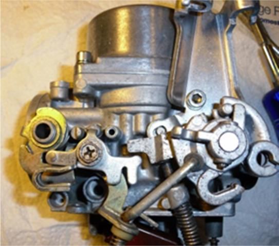
Table of Contents
PURPOSE............................................................................................................................................................................................................... 3
BASIC CARB TERMS ............................................................................................................................................................................................... 3
GETTING STARTED................................................................................................................................................................................................. 3
    BASIC TOOLS .................................................................................................................................................................................................................... 4
    SPECIALTY TOOLS .............................................................................................................................................................................................................. 4
    WITHOUT CHEMICALS, LIFE ITSELF WOULD BE IMPOSSIBLE........................................................................................................................................................... 5

PARTS LIST ............................................................................................................................................................................................................ 5
    HARDWARE ..................................................................................................................................................................................................................... 6
    “SOFTWARE”................................................................................................................................................................................................................... 6
STEP 1 - BANK BREAKDOWN.................................................................................................................................................................................. 7
    SPLIT THE BANK ................................................................................................................................................................................................................ 7
    DOWN TO SINGLE CARBS .................................................................................................................................................................................................... 7
STEP 2 -INDIVIDUAL CARB BREAKDOWN ............................................................................................................................................................... 9
    SYNC SCREWS .................................................................................................................................................................................................................. 9
    TOP END ...................................................................................................................................................................................................................... 10
    AIR CUTOFFS ................................................................................................................................................................................................................. 11
    SPECIAL CARB #2 PARTS TO REMOVE ................................................................................................................................................................................... 11
    BOTTOM END (THE SCARY STUFF) ....................................................................................................................................................................................... 11
    ACCELERATOR PUMP IN CARB 2 ......................................................................................................................................................................................... 13
    THROTTLE BUTTERFLIES .................................................................................................................................................................................................... 14
STEP 3 - OFF TO THE CLEANERS.............................................................................................................................................................................14
    CLEANING THE BIG PARTS .................................................................................................................................................................................................. 15
    CLEANING THE SLOW SPEED JETS ........................................................................................................................................................................................ 18
    CLEANING THE ACCELERATOR PUMP NOZZLES ....................................................................................................................................................................... 19
    CLEANING CARB #2 ......................................................................................................................................................................................................... 20
    CLEANING THE LITTLE PARTS .............................................................................................................................................................................................. 20
    SPECIAL THINGS TO LOOK FOR ............................................................................................................................................................................................ 21
STEP 4 - REBUILD – GETTING IT TOGETHER ...........................................................................................................................................................21
    INDIVIDUAL CARB ASSEMBLY ............................................................................................................................................................................................. 21
        (Benny and the) Jets ............................................................................................................................................................................................. 22
        Float Valve Seats (Shine on you crazy diamond) .................................................................................................................................................. 23
        Pilot Screws .......................................................................................................................................................................................................... 23
        Float & Valve........................................................................................................................................................................................................ 24
        Finishing out the Bottom End (1, 3 & 4) ............................................................................................................................................................... 24
        Special Carb 2 Assembly....................................................................................................................................................................................... 26
        Accel Pump and Bowl Install ................................................................................................................................................................................ 27
        Air Cuts................................................................................................................................................................................................................. 28
STEP 5 - BUILDING UP THE CARB BANK .................................................................................................................................................................29
    RIGHT SIDE (CARBS 3&4) ................................................................................................................................................................................................ 30
    LEFT SIDE (CARBS 1&2)................................................................................................................................................................................................... 30
    MAKING THEM WHOLE (LEFT & RIGHT) ............................................................................................................................................................................... 32
    FINAL ASSEMBLY ............................................................................................................................................................................................................ 34
STEP 6 – ADJUSTMENT, TESTING & TROUBLESHOOTING.......................................................................................................................................35
    ALIGNMENT................................................................................................................................................................................................................... 35
    FINAL TOUCHES .............................................................................................................................................................................................................. 38
    BYPASSING THE AIR CUTOFFS ............................................................................................................................................................................................. 39
    REMOVING BUGGERED-UP PILOT SCREWS ............................................................................................................................................................................ 40
SERVICES OFFERED ...............................................................................................................................................................................................42

© 2010 & 2013 – MacGregor Carb Cleaning Service
Purpose
     The purpose of this booklet is to de-mystify the 4-ganged carburetor banks used on
     the ’79-’83 Honda DOHCs (750cc – 1100cc). Having some basic tools, plus a few
     inexpensive specialty tools, a modicum of mechanical capability and common sense
     - you can tear down, clean and rebuild your carbs in a short weekend. This booklet
     will show you how. The pictures shown are for a CB900, but will be nearly identical
     for CB750, CB1000 and CB1100 with slight differences, which will be noted. The
     process is in 6 steps:
         1. Bank breakdown
         2. Carb breakdown
         3. Clean
         4. Carb rebuild
         5. Bank rebuild
         6. Adjustment, testing and troubleshooting

Basic Carb Terms
     The carbs are numbered the same way as the cylinders on the bike – 1 through 4
     left to right as you sit on the bike. The fronts of the carbs have the silver-colored
     throttle plates (butterflies), and the rear of the carbs have the brass-colored choke
     plates. The round tops are called caps and the square bottoms are called bowls.

Getting Started
     First, get yourself an area
     to work – it can be a
     good-and-proper shop
     workbench, or even a
     simple table (appropriately
     covered and protected
     from spilled liquids and
     solvents) and a comfy
     chair. My downstairs
     basement is set up with
     just a large coffee table covered with thick cardboard. You need to have enough
     room to set up your tools, layout the parts of the carbs and a cleaning area to clean
     the parts. You’ll want a plastic pan such as those used for oil changes for cleaning
     the individual parts prior to assembly. It should be impervious to the chemicals
     used in spray carb-cleaner or brake-cleaner.

© 2010 & 2013 – MacGregor Carb Cleaning Service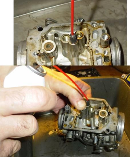
Additionally, you’ll want a copy of the Factory Service Manual to refer to as you go.
The FSM is the bible by which all work on our bikes should be validated.
Finally, make sure you read through this booklet all the way through at least twice to
familiarize yourself with the procedures BEFORE you start disassembly. Nothing
worse than ending up with a pile of really important looking parts after it’s all back
together! If you don’t feel completely confident in what you find in this booklet, by all
means grab a digital camera, a bunch of plastic sandwich bags and a Sharpie® pen
and document your work as you go.
Basic tools
In addition to your workbench and cleaning
tray, here’s what I recommend for basic
tools:
Medium flat-blade screwdriver
Medium Phillips-head screwdriver
Large Phillips-head screwdriver
Small flat-blade screwdriver
Vice-Grips®
4” Crescent wrench
1” wire brush (1 each steel and brass)
Needle nose pliers
Package of 4” acid brushes (sometimes called solder-flux brushes) with the
bristles trimmed to ¼” length
Paper towels & Q-Tips®
Additional tools that you might need:
Flat file
Flashlight
Magnifying glass
Box-knife
Ultrasonic cleaner (Harbor Freight has them for about $60)
or
Large bucket to soak your carbs in
Specialty tools
Over and above the tools noted previously, here are some specialty tools that will
make the job a snap (and some you’ll need for other jobs on the bike anyway):
Motion-Pro carb sync tool (shown at the top of page 36)
High E-string from an old guitar (approx .012” diameter)
4 © 2010 & 2013 – MacGregor Carb Cleaning Service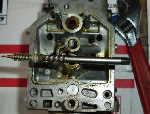
Paperclip (straightened out) with
1/8” 90º bend at the end (on the
right in the picture)
Center-punch (not shown)
Hand drill and assorted drill bits
from 1/32” to 1/8” (not shown)
Small EZ-Outs®
Special spray-straw taped up to fit
in slow-speed jet hole (just to the
left of the paperclip)
without Chemicals, life itself would be impossible...
In addition to the tools, you’ll need some wet-stuff to make the cleaning job go
easier.
¾ Gallon can of carb-degreaser (with small-parts basket)
and/or
Gallon jug of Pine-Sol® or other
ammonia-based pine cleaner
Carb (or brake) cleaner spray with
straw spray nozzle
WD-40 or a can of your favorite spray
lube (I use white lithium spray
grease)
PB Blaster to loosen corroded screws
and parts
Nitrile or Latex gloves – these
chemicals can be pretty nasty on the
skin (not to mention carcinogenic)
Wrap-around eye protection (required safety equipment to protect your eyes
from the spray chemicals!)
Kona Pipeline Porter or other adult beverage (optional)
Parts List
So you got your carbs and your carb rebuild kits – well done. If you bought the
Randakk kits, you’re golden – everything you need is in those kits - but here are
some parts that are left out of most after-market rebuild kits, as well as some
niceties that make the job go smoothly.
© 2010 & 2011 – MacGregor Carb Cleaning Service 5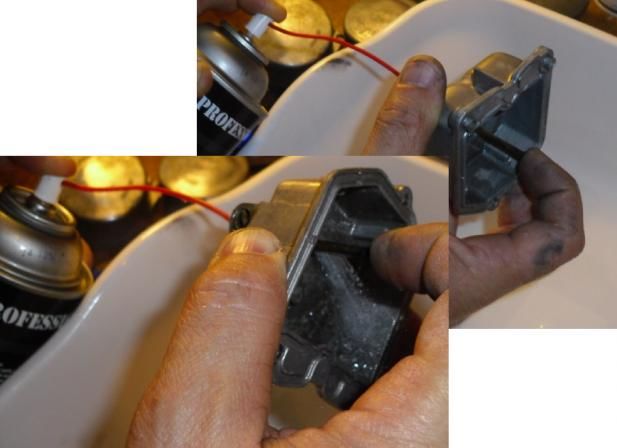
Hardware
Allen head screws to replace those ridiculous Phillips head screws that come stock
on the carbs:
Qty 8 3mm x .5 x 6mm socket button-head screws (for the choke plates)
Qty 12 4mm x .7 x 16mm socket-head screws (bowl screws)
Qty 11 4mm x .7 x 10mm socket-head screws (air cut covers and accel pump
cover)
Qty 16 5mm x .8 x 16mm socket-head screws (top caps and rear frame)
Qty 8 6mm x 1.0 x 12mm socket-head screws (front frame)
Qty 23 4mm split washers
Qty 16 5mm split washers
Qty 8 6mm split washers
I like Bolt Depot for my hardware (http://www.boltdepot.com/), but you can also try
other on-line places. Try to get stainless grade A-2 (also known as 18-8).
“Software”
As I said, the Randakk kits give you all the soft parts you’ll need (gaskets, O-rings,
air cut valves, passage plugs, float needles, etc., etc.). But if you get any of the
myriad rebuild kits from flea-Bay vendors, make sure you buy 4 new air cutoff kits, a
new accel pump kit and a set of 4 rubber passage plugs. All that being said, you
may need a couple of other items.
Often, the flea-Bay rebuild kits are short on the O-rings. O-rings for our carbs come
in standard AS568 sizes that are called dash #’s (-xxx). So here’s what you need
for a full complement to complete the carbs:
Qty 6 -010 Fuel rail O-rings
Qty 6 -007 Accel pump O-rings
Qty 4 -003 Pilot screw O-rings
Qty 4 -006 Float bowl drain screw O-rings
Qty 1 -901 Float bowl #2 accel pump O-ring
Qty 1 1/8” rubber cap for the #2 vacuum “tit” (if carbs have a vacuum-actuated
petcock, and you’re bypassing it)
I use Marco Rubber (www.marcorubber.com), but there are other on-line suppliers.
Remember to get Nitrile O-rings (also called Buna-N), as these won’t deteriorate
from contact with fuel or fuel additives like regular neoprene rubber ones do from
your local hardware store (HomeDepotLowesAceTrueValueMenards).
6 © 2010 & 2013 – MacGregor Carb Cleaning Service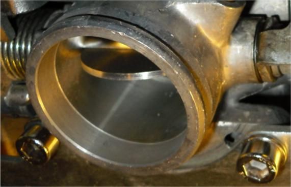
Step 1 - Bank Breakdown
     OK, let’s dive in – you’ve got all your parts, tools, chemicals
     and the star of the show – your filthy, misbehaving carb bank.
     We gotta break this bank down to its individual parts so we
     can get everything squeaky clean and inspected.
     Make sure the carbs are drained beforehand by unscrewing
     the bowl drains 2 full turns and draining the fuel into an
     appropriate container. Dispose of properly (NOT down the drain!).

Split the Bank
                                 Remove all hoses from the bowls and any fuel lines from
                                 the carbs. If your bike has the vacuum-assisted petcock
                                 on it (AKA Spawn of Satan or SOS), remove it, but keep
                                 all the tubes connected to it.
                                 Start with the carbs facing down - smaller diameter ends
                                 on the table, and choke plates facing you. Remove the
                                 eight 5mm screws holding the
     top/rear rail on. If reusing the screws, set them aside. If
                                 using new Allen-heads, toss these
                                 Phillips screws.
                                 Turn the carbs on their tops and
                                 remove the eight 6mm screws
                                 from the front rail (you may need a
                                 pair of Vice-grips® to loosen these). At this point the
                                 carbs are very unstable, so carefully reposition them as
                                 one unit face down. Don’t pull the bank apart, yet, or you’ll
     damage the light spring that’s on the choke shafts between carbs 2 & 3.

Down to Single Carbs
     Carefully unhook the small spring from the hook on the #3/4 choke shaft – it will
     unwind around the #1/2 shaft (that’s
     OK). Split the bank in half with 1&2
     as one set and 3&4 as the other
     set.
     Pop out the fuel rail tube (larger of
     two aluminum tubes with O-rings on
     it), and the accel pump rail tube
     (smaller of 2), as well as the vent
     “T” and rubber tubes that are on it.
     Set aside the vent “T” and rubber tubes – you don’t want nor need to clean these
     with the chemical process you’ll use on the carbs, since the chemicals you’ll use

© 2010 & 2011 – MacGregor Carb Cleaning Service                                              7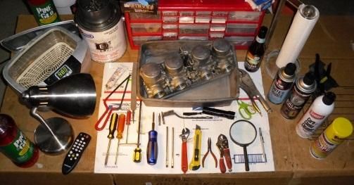
might damage them. Set them aside where you can find them later. Place the fuel
    and accel pump rail tubes in your tray for cleaning. Note: if this is a CB1000 or
    CB1100 bank, there won’t be a fuel rail tube between 2 & 3.
    Start with the 3/4 set – rotate the choke shaft so that the 4 choke plate screws are
    accessible. Carefully and slowly, unscrew them making sure you don’t strip them
    out (drilling these out can be problematic). The screws are
    flared on the backside to keep them from rattling loose from
    normal bike vibration (and getting sucked into the intake),
    so they take some work to remove. Here is where you
    might want the larger Phillips screwdriver to get a good bite
    on the screws.
    Set aside the screws if reusing - though I strongly
    recommend using new stainless 3mm socket button-head
    screws here. The old screws are very difficult to get restarted in the shaft holes
    once they’ve been flared, so if you can, use new 3mm screws and throw these old
    ones away.
    Place the 2 choke plates in the small parts tray for later cleaning.
    Slide the choke shaft out and put with the other parts in the small-parts tray. Pull
                                            the 3 & 4 carbs apart and remove the fuel rail
                                            and accel pump tubes as well as the vent
                                            rubber tube. Don’t lose the little throttle spring
                                            that pops out from between the 2 carbs, you’ll
                                            need it later! Set aside the rubber tube and
                                            put the rail tubes, choke plates and throttle
                                            spring in the small parts tray. Note: if this is a
                                            CB1000 or CB1100 bank, there won’t be a fuel
                                            rail tube between 3 & 4, but this will be a small
                                            brass T-fitting with O-rings.
    Now move on to the carb 1 & 2 set – this set is a bit trickier to break apart because
    you have to hold the choke arm closed with one hand while you remove the choke
    plate screws with the other. Take your time, and again, make sure you’re getting a
    good bite with the screwdriver – you don’t want
    to strip out those screw-heads.
    Once you’ve removed the 4 choke screws,
                                           carefully
                                           remove the
                                           choke shaft
                                           and choke
                                           spring (it will
                                           be hooked
                                           to the main choke arm).

8                                                                   © 2010 & 2013 – MacGregor Carb Cleaning Service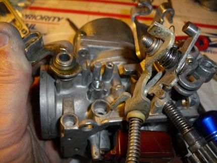
Before popping 1 & 2 apart, remove the
rear cap screw off #1 – this holds a clip
that keeps the brass fuel source “T” from
moving around.
Again, set aside the rubber vent tube, and
place the fuel “T”, accel pump tube, choke
plates and throttle spring in the small parts
tray.
Parts set aside:
Vent T with rubber
connection tubes
2 rubber vent tubes
Parts in the cleaning tray:
Eight 5mm screws and eight 6mm screws (unless replacing w/Allen heads)
Front and rear rails
Two 1” throttle springs
4 choke plates
2 choke shafts & 1 choke shaft spring
Fuel “T” and 2 fuel rails (may be 2 fuel
“T’s” only if this is a 1000 or 1100 bank)
2 short and one long accel pump rail
tubes
Step 2 -Individual Carb Breakdown
OK, so you should be gaining confidence in your ability to work with these
convoluted creatures – heck, you’ve successfully taken the bank apart, and
nothing’s broken yet! Now it’s time to get jiggy with the carbs themselves.
Fortunately, each one is a copy of the others (with the notable exception of carb #2).
We’ll start with carb #1 and move on to #3 & #4. Pay attention to your first one and
the other two will go just like it! Carb #2 will be the last one we do since it’s more
complicated; it may look scary, but we’ll get you through it.
Sync Screws
Before we dig into the guts of the carbs, let’s remove one last external item – the
synchronizing screws off carbs 1, 3 & 4. Here’s where you’ll want that specialized
Motion-Pro tool (see picture on page 36) to loosen the locknuts and remove the
sync screws themselves. If you don’t have the good-and-proper tool, you can use a
© 2010 & 2011 – MacGregor Carb Cleaning Service 9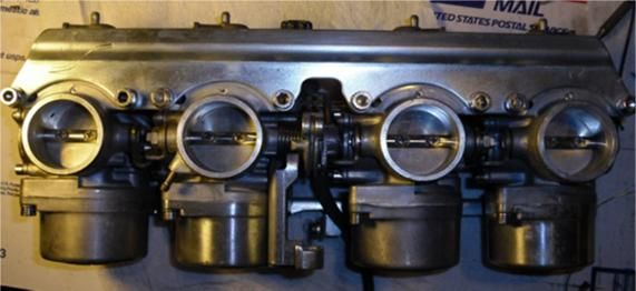
4” crescent wrench, or an 8mm socket to loosen the
     locknuts. The screws are removed from their tabs by
     screwing them INTO the tabs (clockwise). There are 2
     flat washers and a small spring on each one – don’t lose
     them. Add them to the small parts tray (cinch the
     locknut down on the spring first, though, so you don’t
     lose any little parts).

Top End
     OK, let’s remove the easy stuff – the top-caps, springs and vacuum needle “pucks”.
     Again, if reusing the screws, set them in with the small
     parts tray; otherwise toss ‘em.
     Once you have the top-cap, spring and puck removed,
     remove the plastic seal-ring and the kidney-shaped
                                              plastic air jet
                                              cover. Put the
                                              springs, seal-
                                              rings and air jet
                                              covers (with
                                              screws) in the
                                              small parts tray.

10                                                              © 2010 & 2013 – MacGregor Carb Cleaning Service
Air Cutoffs
Carefully remove the 2 screws holding the air cutoff
cover while holding the cover down (there’s a strong
spring under the cover). Before putting the cover and
the spring in the small parts tray, inspect the cover and
body to make sure the small
O-ring isn’t stuck in it (it’s
usually in the body) – either
way, remove it and set it
aside. Remove the air cut
diaphragm and inspect with
strong backlighting to ensure
it isn’t cracked, worn, perforated or otherwise
compromised. It is possible to reuse these or bypass
them altogether. We’ll get to that in the rebuild section. If
you’ve already bought new ones, just toss the old
diaphragms, springs and O-rings – your new kits should
have all these parts. Put the screws in the small parts
tray, unless replacing with new socket heads.
Special Carb #2 parts to remove
Remove the throttle cable mount (held in place by a 5mm
Phillips screw), high
idle knob, washer and
spring, and the choke
idler arm, spring and
washers (be gentle
with the spring - it’s
delicate).
Place all these parts in
the small parts tray.
Bottom End (the scary stuff)
OK, let’s dive into the “scary stuff” (it’s really not that
scary). Remove the bowl drain screws and put them in
the small parts tray. Then remove the three 4mm
screws holding the float bowl in place and pull the bowl
off – you may have to rap on the bowl with the handle-
end of the screwdriver to break it free. Set the bowl
© 2010 & 2011 – MacGregor Carb Cleaning Service 11aside, and put the screws (if reusing) in the small parts tray.
Inside, you’ll see the jets, the float and the passage plug. Next we’ll remove the
float. Take that straightened out paperclip you made in the tools section above and
push the float pin out; the float and float valve will come out together. Set the float
and valve aside, and put the pin in the small parts tray.
Remove and toss the rubber passage plugs (you’ll be installing new ones later).
Use a medium flat-blade screwdriver
to remove the primary main jet
(screwed directly into the body of the
carb). Use your crescent wrench to
remove the brass secondary main jet
emulsion tube (it has the secondary
main jet screwed into it). Put both
these into the small parts tray.
Special note – the silver needlejet is
held in place by the secondary main
jet
emulsion tube, and MAY fall out when you remove
the tube. If so, put it in the small parts tray as well.
Now take a look down the pipe that the rubber
passage plug came out of. Look to see if the slow-
speed jet has a slot in it for a flat blade screwdriver
(later ‘81s through the ‘83s had removable slow-
speed jets; earlier ones were press-in and not
removable). If the slow-speed jet has a slot in it,
remove it by unscrewing it with a small flat blade.
Remove the primary main jet emulsion tube
by using the screwdriver part of the Motion-Pro
sync tool (it fits perfectly in the hole). Get a good
bite on the slot and don’t force it. These get
Slow-speed jet down
corroded in
here sometimes
and you can
do more damage to the thing by stripping out the
screw slot. If it’s stuck in there, try spraying some
PB-Blaster down the hole and let it sit overnight.
Worse case, you can clean the carbs with the
Primary main jet
emulsion tube down
emulsion tube still installed – don’t damage it
here unnecessarily trying to remove it if it’s good-and-
12 © 2010 & 2013 – MacGregor Carb Cleaning Servicetruly stuck. If you were able to remove the emulsion tube and if the slow-speed jet
was removable, place both in the small parts tray.
Remove the pilot screws by unscrewing them counter-clockwise. Inspect it to
ensure it has a 1/8” needle tip to it as shown
in the pics. When removing the pilot screws,
they may come out with the spring, or the
spring may remain in the body – here’s where
you want the other end of the paperclip.
Use the 90º “hook” to fish out the spring (if it
didn’t come out with the pilot screw), and the
flat washer and O-ring. Here’s where your flashlight
will help. Put the pilot screw, spring and flatwasher in
the parts tray – toss the O-ring.
If your old pilot screws
had the silver stop tabs
on them, you can O-ring
remove them by using a Flat washer
heat gun or a hairdryer
on high temp setting. A
pair of needle nose pliers will suffice to take them off.
There should be enough glue still inside the cap to heat up when you’re ready to put
them on your new pilot screws.
Accelerator Pump in Carb 2
Carb #2 is special in a number of ways, as you’ve already seen.
The last special thing we’ll work with is the accelerator pump –
a small diaphragm, spring and set of special check-valves that
squirt fuel directly into the throat of each carb when the throttle
is twisted briskly. This is meant to overcome the “turbo-lag” of
the heavy vacuum needle pucks that make these CV carbs so
unique.
You’ll notice when you removed the #2 carb bowl, there were 3
other screws on the base of it – this houses the pump. Be careful with the shaft that
pokes up out of the bowl – don’t bend it! Remove the
three screws (hold on to the cap as there’s a strong
spring underneath). Remove the cap, the spring and the
diaphragm/shaft. While the diaphragm and spring can
be reused, it’s better to replace ‘em – usually only about
$25 from most e-Bay vendors. Place the screws (if
reusing), accel pump cap and spring in the small parts
tray.
© 2010 & 2011 – MacGregor Carb Cleaning Service 13Set the diaphragm/shaft aside after inspecting for
stiffness/brittleness/holes/cracks/thin-spots with a
back-light. You hopefully still have a small rubber
bellows that fits in the #2 carb body that the accel
pump shaft went through. Check its condition and
set aside with the other rubber parts. Special
note about foreign carbs: Not all carbs sold by
Honda are the same. Many of our UK-associated
bikes (Britain, South Africa, Australia, etc.) do
NOT have an accel pump. Instead, carb #2’s
bowl looks just like carb #1’s bowl. So IF you have a set of these simpler carbs, just
ignore all references to accel pump in the document.
Throttle Butterflies
I don’t recommend removing the throttle butterflies and throttle linkages. A couple
of reasons for that: You risk damaging or tweaking the shafts unless you remove the
parts in the right order, you risk losing or damaging the small felt washers that are
inside the bronze inserts (these parts were not offered by Honda, so you’d have to
make new ones if you lose/damage one), and there’s a high probability of getting
the fiber and metal washer sequence buggered up on re-installation and creating
paths for an air-leak. Frankly, the risks don’t warrant the additional cleaning you
could get on those parts, so I say – leave ‘em on. OK, now on to cleaning…
Step 3 - Off to the Cleaners
OK – You’re a third of the way there, and the parts tray is getting pretty full! In
addition to the parts I detailed in the bank breakdown section above, you should
have:
3 sync screws with springs, locknuts and flat washers
4 primary main jets
4 secondary main jets in their emulsion tubes
4 float pins
4 pilot screws/springs/flat washers
4 top-cap springs
4 float-bowl drain screws
4 top-cap plastic seal rings
4 top-cap plastic air-jet covers and screws
1 throttle cable support bracket and 5mm screw
1 high-idle screw/knob/washer/spring
1 choke idler arm with spring, bolt, flat and split washers
14 © 2010 & 2013 – MacGregor Carb Cleaning Service
4 air cutoff springs, covers and screws
1 accel pump cover, spring and screws
4 primary main jet emulsion tubes (if you were successful in removing them)
4 slow-speed jets (if the removable type)
1 or more silver needle-jets (if they came out with the secondary jet emulsion
tubes)
Set aside should be:
4 air cutoff diaphragms
4 air cutoff diaphragm O-rings
4 floats
4 float valves
1 accel pump diaphragm/shaft and rubber bellows
And of course the big parts:
4 carb bodies
4 carb caps
4 vacuum “pucks”
4 float bowls
OK, it’s time to clean this stuff up!
Cleaning the big parts
As seen in this pic, I use both the
Carburetor and Small Parts Cleaner Dip
from Gunk® and a 3-quart ultrasonic
cleaner. The Dip comes in a 3-quart can
and has a nice perforated small-parts
basket, which can safely hold even the
smallest of all the parts in your parts tray.
The ultrasonic cleaner is the same size
and can take a full carburetor (body, cap,
puck and bowl). Used together, they’ll
clean off nearly all your caked on oil and
grime from the outside of the carb, as well
as the varnished gasoline throughout all
internal surfaces of the carb bodies. Now
others will swear by a simple 2-gallon pail,
and a gallon of Pine-Sol®. It’s up to you –
both methods work well.
I place the carb body face down in the
basket and lower it into the Dip, then (after
© 2010 & 2011 – MacGregor Carb Cleaning Service 15removing the float-bowl gasket) position the other 3 major pieces around it so
they’re all covered in the thick liquid. Let it sit in there anywhere from 15 minutes to
overnight depending on how nasty your parts are. Usually 30 minutes is plenty.
Remove the parts and put in the ultrasonic – I use Pine-Sol® as the liquid for the
ultrasonic. I run ‘em for 15 to 20 minutes, then put them in the cleaning pan and
repeat the whole process for the next carb. You may have to turn the bodies in the
ultrasonic, so all the surfaces are well vibrated.
If you use the simple Pine-sol®-‘n-bucket method, place all the parts in the bucket,
fill with Pine-sol® and let sit overnight. Don’t let them sit for more than a day though
without rinsing, as the Pine-Sol® may attack the aluminum.
After you get them out and rinsed/dried, it’s time to put on the eye protection as we
clean the carb body.
Take a couple of the acid brushes, trim the bristles down to about ¼” and use the
spray carb cleaner to clean out those nooks and crannies on the bodies. Use the
carb cleaner generously throughout the carb body, and use the acid brushes to
attack any dirt that the Dip and ultrasonic cleaner didn’t remove – you want the
bodies spotless on the inside.
Clean the top-cap with the carb spray, and use a paper towel stuffed loosely in the
center tube to buff it clean, as well as the inside of the top-cap itself – any schmutz
inside here will impede the puck’s vacuum movement and affect the bike’s
operation. Take the straw and spray through the little hole on the side of the top-
cap inner tube – it should spray into the inner tube.
Spray down the vacuum puck and use the acid brush to clean off any varnished gas
on it or the needle. Stick some of the paper towel down between the inner edges of
the puck and its center shaft – just like the top-cap, any schmutz here will impede
the puck in its travels.
Use the carb cleaner spray and the acid
brushes to clean out any residual gunk in the
bottom of the float bowl. Use a Q-Tip® to
clean out the seat of the float bowl drain
screw. Start with a full tip, and then pull off
enough of the cotton off the end of the Q-Tip®
to go all the way through into the base of the
float bowl. Trust me; they’ll be black with goo
– keep using the Q-Tips® and carb spray until
they are clean.
Take the spray straw and an Exacto®-type
knife and whittle the tip to a more conical shape so it fits better into some of the
holes you’ll be spraying into (this will keep the back-spray into your face to a
minimum – don’t ask me how I know this…).
16 © 2010 & 2013 – MacGregor Carb Cleaning ServiceSpray a good shot into each hole as
follows:
Primary main air jet
Secondary main air jet
Secondary slow air jet
Primary slow air jet
Air cutoff feed
Air bypass
Also
Float valve seat
Slow-speed jet
Accel pump feed hole
(shown later)
Primary main jet
Pilot screw
Secondary main jet
© 2010 & 2011 – MacGregor Carb Cleaning Service 17Cleaning the Slow Speed Jets
There’s nothing more important for proper carb operation than having clean slow-
speed jets, so I’m going to dedicate several pix to help you.
If the jets were removable, you’re golden - just blow them out with some carb
cleaner before reinstalling, but if the slow-speed jets were the pressed-in variety,
and you could not remove them in the carb breakdown section, you need to prep
them for spray-down:
Take that E-string we
had you get, and push
it through the center
hole down in the
center tube – don’t
force it; you may need
to twist it as you go,
but you want to be
able to push down
about 1-1/2” of the E-string down the hole
to be sure you’ve cleared the slow-speed jet.
They gunk up easily and will cause no end of grief if you don’t get
them cleared. Don’t short-change this step – it’s critical.
Once cleared with the E-string, here is where you want to modify the straw. Take
enough electrical tape and wrap it around the end so
that it will fit fairly
snug in the slow-
speed jet tube. Hold a thumb over the primary
main-jet hole and your index finger over the lower
air cutoff hole and
spray. If the slow-
speed jet is truly clear,
you’ll get a
bubbling (or
stream) of carb
spray out the pilot
screw hole. Don’t
consider the carb
cleaned until you
can do that!
18 © 2010 & 2013 – MacGregor Carb Cleaning ServiceCleaning the Accelerator Pump Nozzles
Finally, check that the accel pump nozzle
is clear by setting the carb down on its
front, carefully place the conical nozzle of
the straw into the accel pump rail hole
and watch the pump nozzle as you spray –
you should get a nice clear stream out
the pump nozzle tip. On carb #1, the rail
hole is on the right side of the carb. On
#4 it’s on the left. On carb #3 you can go
from either side, just cover the other rail
hole with your finger so the spray goes
out the nozzle. Clearing that nozzle is a
bugger, as it’s a blind hole on the carb-
body side of the nozzle. You can use your needle-nose pliers to hold the E-string
and blindly search for the hole – once you’ve found it, wiggle the string in there, and
try again. You may have to soak the carb body and run it through the ultrasonic
cleaner again to clear this nozzle.
That should take care of all the big parts – drop the puck into the top cap and make
sure it slides effortlessly – polish the inside of the cap and the puck again with a
paper towel, if you get any hesitation. Also polish the vertical sides of the carb body
where the puck goes with a paper towel to further ensure proper carb operation.
If you want to polish your carb caps and bowls to a chrome-bright shine, now would
be the right time to get that done.
© 2010 & 2011 – MacGregor Carb Cleaning Service 19Cleaning carb #2
Everything you did on carbs 1, 3 & 4 will be done on carb #2, but there are more
nooks-‘n-crannies to deal with – take the time
to clean the body well with the acid brushes
and carb cleaner.
To clear the accel pump nozzle on carb 2, the
hole is accessed from the bottom of the carb,
with your thumb
and forefinger
covering both rail
holes. Also, the
float bowl has a
check-valve that
needs to be cleared. Spraying into this hole should
result in a jet of spray out each of the 4 sides
of the square brass insert. You may have to
soak the bowl further if this check-valve is
clogged.
Cleaning the little parts
The easiest way to clean the little parts is to
soak them in the Dip tank for 30 minutes, then
ultrasonically clean them for 30 minutes. Spray them down with carb cleaner, touch
‘em up with the acid brushes, and dry them in preparation for rebuild.
3 parts you’ll want to do some extra effort on: choke shaft 1/2, choke shaft 3/4, and
the accel pump cap.
Use a brass brush to get the residual crud off the choke shafts and get ‘em shiny-
bright (they need to be able to spin easily in the choke shaft bushings in the carb
bodies). Be careful not to bend the shafts.
And just like in the #2 float bowl, there’s a check-valve in
the accel pump cap
that needs to be
cleared. The carb
spray nozzle should fit
down the larger of the
two holes in the cap,
and the spray should
come briskly out each
of the 4 sides of the square brass insert. If it
doesn’t, you’ll need to soak the cap longer and
run it through the ultrasonic again.
20 © 2010 & 2013 – MacGregor Carb Cleaning ServiceSometimes you can soak just the check-valve, by setting the cap right side up in the
spray-can cap, and fill it with carb spray. Let it sit for an hour or so, and try again.
Run spray through each jet and emulsion tube, paying special attention to the
aeration holes on the sides (make sure they’re clear).
Special things to look for
There’ve been a few parts that have been set aside that now need to be looked at.
Take each float and hold it near your ear and shake it back and forth – if you hear
ANY sloshing about, you need to replace it, as it developed a leak where fuel is
getting inside, and it won’t work right for you. If the carbs have been sitting for a
while, the fuel may have evaporated out of an otherwise leaking float, so you might
want to put each of them in a cup of water, with something to hold them down. Let
‘em sit for an hour or so and check again with the shake test.
If you didn’t get new float valves with your rebuild kit, it is possible to reuse your old
ones – look closely at the rubber tip with a magnifying glass and make sure it’s
conical, a bit pliable and doesn’t have a groove worn into it. Also, make sure the
silver tip on the other end can be pushed in, and springs back easily when released.
Take a look at the pilot screws under the magnifying glass and make sure the tips
are not damaged or bent. If you get new ones with your rebuild kits, you can chuck
the old ones (actually it’s probably better to save ‘em as spares!).
Step 4 - Rebuild – Getting it Together
OK, we’ll go through this just like the disassembly and cleaning; carb #s 1, 3, 4 then
carb #2.
We’ll build up each individual carb, then gang them together in 2’s then hook the 2
gangs up. Nothin’ to it, eh?
Individual Carb Assembly
Start at the top of the carb. Install the plastic
airjet cover and screw in snuggly (not tightly –
you don’t want to break the cover). Then install
the seal ring – the inner lip should be facing up.
Take the vacuum “puck” and drop it down into
the top of the carb. The groove in the side of
the vacuum puck fits neatly on the tab sticking
out from the airjet cover. Look through the rear
of the carb as you drop the puck in, so the
needle fits into the needle jet (sticking up above
the bottom of the throat of the carb), and the
groove fits onto the tab of the airjet cover. If
the needlejet came out with the needlejet holder (back on step 2 middle of page 12),
© 2010 & 2011 – MacGregor Carb Cleaning Service 21you won’t see it in the carb throat – we’ll install it in the next
step – don’t worry.
Now install the spring onto the already installed puck and
install the carb cap on the spring (make sure the spring fits
around the outside of the brass center tube of the carb cap).
Snug it all together with two 5mm screws.
(Benny and the) Jets
Take your magnifying glass and look along the edges of all 4 primary main jets and
secondary main jets. There should be some markings on them like K68 or K105.
Make sure all the primaries are the same number, and all the secondaries (in their
emulsion tubes) are the same number. Invariably during a previous clean/rebuild,
the owner will have removed the secondaries from their emulsion tubes and mixed
them up with the primaries on reinstall. That’s why I recommend removing the
secondary emulsion tube while leaving the jet installed in it – keeps this mix-up from
happening. Stock jetting (with airbox) for our bikes is as follows:
750 – 68 primaries and 100 or 102 secondaries
900 – 68 primaries and 105 secondaries
1000 – 68 primaries and 110 secondaries
1100 – no primaries (and no rubber passage
plug!) and 122 secondaries.
Install the primary main
jet emulsion tube (if
you were able to
successfully remove
them before), and the
primary main jet. Check for the silver needle jet
sticking up above the bottom of the carb throat in
the center of the carb body. If it’s
missing, and you have one or
more in the clean tray, install it
now. It will only go in one way, so
don’t force it – The conical end goes up, and the rounded end
goes down.
22 © 2010 & 2013 – MacGregor Carb Cleaning ServiceInstall the secondary main jet
emulsion tube (this will hold
the needle jet in). Now, if you
removed the slow-speed jet,
install it now and put in a
fresh rubber passage plug –
make sure it fits snugly and
doesn’t fall out when you turn
the carb over.
Float Valve Seats (Shine on you crazy diamond)
Without a doubt, the second most important thing
about your carb cleaning process (right after the slow-
speed jet and passage cleanliness) is the float valve
seats. More people complain about their carbs
pissing fuel out the overflow tubes, and it’s almost
always caused by dirty float valve seats. Get yourself
a handful of Q-Tips®
and some Brasso®,
or other metal polish (or even some toothpaste, if
you don’t have any polish). Polish those seats
until they shine. Examine them with a magnifying
glass and flashlight to make sure there are no pits,
grooves or damage down near the edge of the fuel
entrance hole of the
seats.
Pilot Screws
Slide the spring on
the pilot screw,
followed by the flat washer then a new O-ring.
Screw the whole assembly into the body of the
carb. Screw it all the way in until you feel
resistance – DON’T
force it, or the little
neck below the
threads will give
way, and you’ll be
getting out the drill and EZ-Outs®. Once the flat
section below the thin neck is even with the bottom of
the pilot screw hole, you’ll be bottomed out. On the
900, 1000, and 1100 carbs, you will see a bit of the
pilot screw tip sticking up through the bottom of the
© 2010 & 2011 – MacGregor Carb Cleaning Service 23carb throat; you won’t be able to see that on the 750’s. Now back the pilot screw
out the following amount:
750’s – 3 turns
900’s – 2-1/2 turns
1000’s and 1100’s – 3-1/2 turns
Float & Valve
You’ve tested your floats and they float! Clean ‘em up
and reinstall them with either new or cleaned-up-and-
tested old valves. Install the valve onto the float and slide
the valve into the seat while aligning the float for the pin.
Slide the pin all the way in so no part of the pin can be
seen on either side of the float holders. Turn the carb on
its nose until the float just touches the silver tip of the
valve and measure the distance between the bottom of
the float and the bottom of the carb body. It should be
within the specs of the Factory Service Manual (15.5mm
+/- 1mm). The brown plastic
floats on the ‘80s and later
bikes are not adjustable as far as float height – if you
have a float level issue with these floats, it’s likely your
valve is bad or the wrong one for that model. On the
’79 CB750’s, you’ll find black floats – the valves are
slightly different (they have a wire clip on them) and the
floats have a metal tang on them that IS adjustable.
Finishing out the Bottom End (1, 3 & 4)
Alright, we are getting close to buttoning up our carbs. Next step is to install new O-
rings on the bowl drain screws. While it’s a good idea to
replace all the old O-rings with new, these screws can
probably be used with the old O-rings; the rings don’t prevent
leakage out the overflow, but just keep the fuel from coming
out the side when the drain screw is loosened. But it IS a good idea to check the
screw tips for damage. They should not be pitted, gouged or missing. Often, water
collecting in the bottom of the bowls will corrode the tips (bad screw on top, good
screw on bottom). Before installing the bowl onto the carb, fill
the bowl with water to within 1/8” of the top of the bowls and
make sure you get no leaks – nothing worse than dealing with
a leaky bowl AFTER you’ve assembled everything and
installed the carbs on the bike.
24 © 2010 & 2013 – MacGregor Carb Cleaning ServiceSometimes, the drain tube will get a crack in it, or the drain screw seat is damaged.
You can fix the tube with some solder or J.B. Weld™.
The only way to fix a damaged drain seat is to replace the
bowl. To check for a cracked drain tube, screw in the drain
screw and snug it down, then hold your finger over the upper
end of the tube and spray
carb cleaner into the drain
nipple– if there’s a crack,
you’ll see carb cleaner
spraying out through it,
otherwise,
it’ll only
come out as
back-spray
out the
drain nipple.
Split drain tube repaired
with J.B. Weld ™
All that’s left now to the bottom end is to install the float
bowl with new gasket. Dry out the bowls well from your
leak test.
I find I have to stretch the bowl gasket gently through
my fingers a few times to get it to seat right in the
groove. I don’t use gasket seal or any adhesive, as the stretching usually works
fine. Place the carb body onto the bowl (with everything upright) so the gasket
stays in place. Place strong pressure on the bowl to hold it in place while you flip it
over and install the three 4mm screws. Loosely install the screws, and then snug
them down evenly before tightening them all up. The passage plug will be forced
completely into the slow-speed jet tube once these screws are fully tightened up.
Now’s a good time to reinstall the pilot-screw cap that you removed before – just
hold it with a pair of needle nose pliers, heat it up with a heat gun or hair dryer and
soften the glue. Align it straight ahead of the tab on the bowl and push on to the top
of the pilot screw. By having it aligned straight ahead, you can still adjust it 1/3 of a
turn in or out without hitting the bowl tab (you may need to adjust the final setting of
the pilot screws on the bike to get the right mixture level).
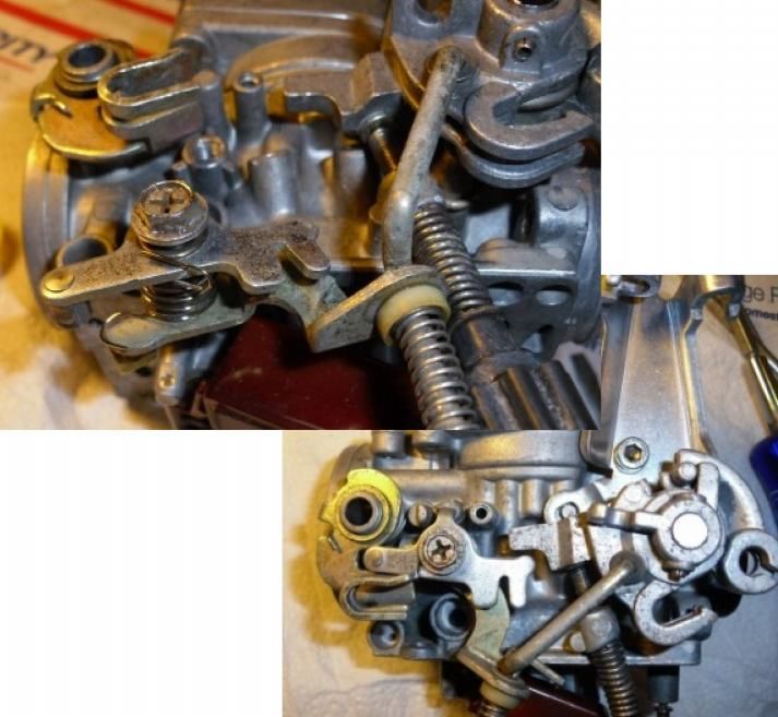
© 2010 & 2011 – MacGregor Carb Cleaning Service 25Special Carb 2 Assembly
Carb 2 assembly takes a bit more. After installing the top-cap,
you need to install the mechanisms on the side. Place the choke
idler spring on the idler (skinny long hook on the bottom of the
idler – round hook towards the back of the idler). Slip the screw-
bolt through the hole and the spring. Install the entire assembly
onto the face of the throttle idler with the screw-bolt going
through the hole in the throttle idler.
Install the flat washer and split washer in that
order onto the screw-bolt. Lift the choke
actuator arm to gain room and carefully install
the throttle/choke idler & washer assembly onto
the carb body (this takes some careful finger
manipulations and patience).
Split Washer
Flat Washer
26 © 2010 & 2013 – MacGregor Carb Cleaning ServiceStart the screw-bolt into the hole on
the body (the idler’s round end
should be towards the back of the
carb, and the forked tines should be
towards the front. Before tightening
down, make sure the round part rides
under the choke actuator arm, and
the tines fit under the
throttle actuator arm,
and the round hook of
the spring should fit over
the solid stud just
forward of the choke
actuator arm.
The whole thing
should end up
looking like this:
Now install the throttle cable mount with the 5mm
screw (the hole on the left goes onto the small stud just
below and back of the screw hole).
While the picture shows it installed, it’s best to hold off
installing the high-idle knob/spring/washer until you’ve
got the bowl installed.
Accel Pump and Bowl Install
Before you install the float bowl on carb #2, you should
install and test the accel pump. Slide the diaphragm shaft
through the hole in the center of the accel pump housing on
the bowl and align the holes on the side of the diaphragm
with the holes in the housing. While maintaining that hole
alignment, install the spring
and screw down the cover with
three 4mm short screws.
Make sure the spring fits over
the check-valve “lump” in the
bottom of the cover. Snug the screws down evenly,
and then tighten them up. Take the whole assembly
out in the garage, and over a large catch pan fill the
bowl about half full with fuel and test the pump
operation. Obviously do this is a safe environment (garage door open, eye
© 2010 & 2011 – MacGregor Carb Cleaning Service 27protection on, gloves on, plenty of shop rags around, no open flames). You should
get a 6-18” fountain of gas squirt out the square brass diffuser when you press
down on the diaphragm shaft (it may take a
couple of priming shots). If you don’t, you need
to troubleshoot – it’s usually a reused diaphragm
that’s shot, or a check-valve that’s not clear.
I recommend using gas, as water can end up
being left in the pump chamber - since it’s the
lowest point on the carbs – it’ll corrode your
newly cleaned accel pump. Gas won’t do that.
Once tested and drained/cleaned up, install a
bowl gasket and the 901-sized O-ring over the bowl diffuser depression. Install the
dust-protector bellows up through the carb body (thicker/wider end of the rubber at
the bottom). Hold the bowl and carb in their upright position
and install the bowl onto the carb, carefully holding the bellows
in place as you guide the shaft through it and make sure the
gasket and O-ring stay in place as you mate the bowl to the
body. Hold the bowl firmly to the body and install the three
4mm long screws – again snug them up evenly, then
tighten down.
Now you can install the high idle knob/screw/spring/washer – the washer should go
between the knob and the spring. Screw it in until it touches
the throttle actuator arm, and then give it another full turn.
Air Cuts
Take the air cutoff cover,
place the conical tip of the
straw into the hole in the
corner and spray – you should get a jet out the
side hole just beside it. If you got new diaphragm
kits, install the diaphragm (make sure the brass tip
easily slides into the hole, and the diaphragm lip
fits securely in the groove). Place the rubber O-
ring in the hole in the lower left corner of the air cutoff hole in the body of the carb.
The flat side should go against the body. Install the
spring (small end towards you), and install the cover.
Make sure the small “tit” on the cover fits into the
small end of the spring. Secure with two 4mm short
screws. Make sure nothing has moved out of place
(diaphragm still in its groove, O-ring still in its spot,
spring still in the diaphragm) and tighten down the screws.
28 © 2010 & 2013 – MacGregor Carb Cleaning ServiceStep 5 - Building up the Carb Bank
Whoo Hoo! Two-thirds there. Let’s review the parts you have on the table, so we
can rectify it before we go any farther:
4 complete carbs with tops, bowls and air-cuts installed
2 choke shafts with spring
2 throttle springs
3 sync screws with spring, washers and locknuts
1 brass fuel “T” (Maybe 2 “T’s” if these are 1000 or 1100 carbs)
2 short and 1 long accel pump tubes
1 short and 1 long fuel tube (or none if 1000 or 1100 carbs)
4 choke plates
1 Fuel “T” clip
1 Vent “T” and rubber joiners
2 rubber vent tubes
Front rail and rear rail with choke cable clip
8 each 5mm and 6mm screws
If you have ANY other parts than these, go back
through the step 4 and see where you left anything out.
Go ahead now and replace the oldie-moldy O-rings on the fuel and accel pump rail
tubes and fuel “T(s)”. A touch of petroleum jelly or WD-40 makes these go on easily
as well as lube them for easy installation into the carb bodies themselves.
© 2010 & 2011 – MacGregor Carb Cleaning Service 29You can also read