Specification for Road Safety Hardware Systems - APPENDIX C: TEMPORARY ROAD SAFETY BARRIER SYSTEMS - Tauren Barriers
←
→
Page content transcription
If your browser does not render page correctly, please read the page content below
Specification for Road Safety
Hardware Systems
APPENDIX C: TEMPORARY ROAD SAFETY BARRIER SYSTEMS

                                                       October 2017

                                       Prepared for NZTA by Parallaxx Ltd
NZTA M23C 2017
INTRODUCTION AND REFERENCES
This hardware summary manual has been prepared to assist
organisations and individuals who interact with Temporary
Road Safety Barrier Systems. The technical details within If you have further queries, call our contact
centre on 0800 699 000 or write to us:
this manual have been extracted from the respective
NZ Transport Agency
product, installation and technical manuals of each device. Private Bag 6995
Wellington 6141
For more detailed information, refer to the individual manuals
This publication is also available on
for each product or contact the System Owner/Supplier. NZ Transport Agency’s website at
www.nzta.govt.nz
The information, commentary and details provided in this manual
are collected from a variety of reliable sources however the
System Owner/Supplier formally issued and endorsed material
must still be used as reference material for products. Do not
utilise a device listed in this manual without first consulting the
System Owner/Supplier and obtaining the correct and most
recent documentation for the product.
This manual is prepared with the intention of providing basic
outline detail on all approved temporary road safety barrier
systems for use by NZTA.
DOCUMENT REFERENCES
CoPTTM (Section B12, Temporary road safety barriers)
CoPTTM (Section C, road safety barrier systems)
NZTA M23
NZTA M23 Interim acceptance notices
AUSTROADS Part 6: Roadside Design, Safety & Barriers
AUSTROADS Part 3: Geometric Design
NZTA State Highway Geometric Design Manual (SHGDM)
The NZTA is part of, and contributes to, the Safer Journeys programme.
Safer Journeys is the government’s strategy to guide improvements in road safety over the period 2010–2020. The strategy’s vision is a safe
road system increasingly free of death and serious injury. It is a co-ordinated effort across partner agencies to improve each aspect of road
safety – better behaviors, a safer road environment, safer speeds and higher vehicle standards.
For more information visit www.transport.govt.nz/saferjourneys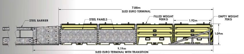
NZTA M23C 2017

Contents

1
GLOSSARY
                    3
                    ABSORB 350 CRASH
                                        5
                                        ACZ-350
                                                            7
                                                            ARMORZONE TL2
                    CUSHION             TEMPORARY CRASH     PLASTIC BARRIER +
                                        CUSHION             ARMORZONE END
                                                            TREATMENT

9
BARRIERGUARD
                    11
                    SLED CRASH
                                        13
                                        SLED CRASH
                                                            15
                                                            J-J HOOKS®
800 STEEL BARRIER   CUSHION             CUSHION (SLED-US)   CONCRETE BARRIER
SYSTEM              (EURO-TERMINAL)                         SYSTEM

17
QUADGUARD II
                    19
                    RICOCHET TL2
                                        21
                                        SCI-100 SMART
                                                            23
                                                            SENTRY WATER-
BARRIER SYSTEM      PLASTIC BARRIER     CUSHION             CABLE BARRIER
                    SYSTEM + RICOCHET                       SYSTEM
                    TL2 END TREATMENT

25
TAU- II CRASH
                    27
                    TRACC CRASH
                                        29
                                        WATER-WALL TL1
                                                            31
                                                            X-TENUATOR CRASH
CUSHION SYSTEM      ATTENUATION         PLASTIC BARRIER +   CUSHION
                    CUSHION             SLED TL1 PLASTIC
                                        END TERMINAL

33
ZONEGUARD STEEL
BARRIER SYSTEM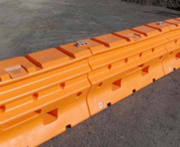
NZTA M23C 2017   |    1

GLOSSARY

Anchorage                    A barrier system may be anchored to the ground to limit deflection.

Bi-directional application   Two-way traffic. E.g. Barrier hardware that can be hit by both adjacent and opposing traffic.

Chevron                      Retro-reflective chevron signs attached to the barrier units to guide drivers along a temporary barrier
                             system (refer CoPTTM B12).

Clear Zone                   A clear zone is the area adjacent to the traffic lane that should be kept free from hazards that could be
                             impacted by errant vehicles.

CoPTTM                       NZTA Code of Practice for Temporary Traffic Management.

Crashworthy                  A feature that has been proven acceptable for use under specified conditions either through crash testing
                             or in-service performance.

Crossfall                    The transverse sloping of the road surface toward the shoulder or gutter.

Deflection                   The horizontal displacement of the barrier when impacted.

End Terminal                 A crashworthy end treatment must be provided when the end of a barrier is exposed to head-on impacts.

Energy Absorbing Unit        The individual units in a crash cushion that absorb impact energy.

FHWA                         USA Federal Highways Administration.

Flare Rate                   The curvature applied near the end of a road safety barrier installation. Expressed as the ratio of the
                             longitudinal distance to the transverse offset, by which a road safety barrier flares away from the road.

Flexible Barrier             Barrier systems which dissipate crash impact energy largely by deflection of the barrier system. Lower
                             impact forces are imposed on the vehicle and occupants.

F-Shape Barrier              Concrete barrier of the current accepted F-shape cross-section.

Gating                       A road safety barrier terminal designed to allow an impacting vehicle to pass through the device, when
                             impacted at an angle, upstream from the point of redirection.

Impact angle                 For a longitudinal barrier, it is the angle between the face of the barrier and the vehicle’s impact direction.

Length of need               The required length of barrier system that is re-directive, to shield the hazard.

MASH                         Manual for Assessing Safety Hardware (MASH) is a Manual for Assessing Highway Safety Features.

NCHRP-350                    National Co-operative Highway Research Program (report) 350.

New Jersey Barrier           Generally a concrete barrier of the New Jersey Barrier profile. Superseded by the F-shape.

Pinning                      Either connecting adjacent transportable barrier sections, or fastening barrier sections to the pavement
                             of ground.

Point of Redirection         That point on a barrier system downstream of which will be redirective. Previously referred to as “point of need”

Proprietary                  A road safety barrier system that is the subject of patent or other intellectual property rights.

Redirective                  The ability of a barrier system to re-direct an impacting vehicle without barrier pocketing or rupture.

Ribbon Strength              The longitudinal strength of a barrier system to provide crash energy containment and redirection.

Rigid Barrier                Barrier system that has no deflection under impact. Higher impact energy transmitted to vehicle
                             and occupants.

Semi-Rigid Barrier           Barrier system deflects during re-direction. Impact energy to vehicle and occupants is less than for a rigid
                             system but greater than a flexible system.

Shy Line                     The distance from the edge of the travelled way outside of which the start of a roadside object (e.g.
                             barrier) will not cause a driver to change their vehicles lateral placement or speed.

Sight/ Anti-Gawk Screens     Screens to shield visual distractions from passing drivers.

Slope                        The relative steepness of the terrain expressed as a ratio or percentage.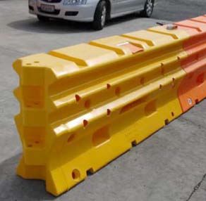
NZTA M23C 2017   |   2

Test Level (TL)               A set of prescribed test conditions, defined in terms of vehicular mass, impact speed and angle that
                              defines the crash energy.

Uni-directional application   One-way traffic. E.g. Barrier hardware that cannot be hit by opposing traffic.

Vaulting                      Abrupt upward movement of an impacting vehicle.

Wear and tear                 Damage that naturally and inevitably occurs as a result of normal use or aging.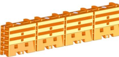
NZTA M23C 2017 | 3
ABSORB 350 CRASH CUSHION
SUMMARY
SUPPLIER: CSP Pacific (http://www.csppacific.co.nz/)
TEST LEVEL / CONDITIONS: TL2 and TL3. NCHRP-350 TL-2 and TL-3
PRODUCT MANUAL click for product manual download
FOR USE WITH Attaches to permanent and temporary steel and concrete barrier
The ABSORB 350 Crash Cushion is approved to NCHRP350 TL-2 & TL-3.
This barrier system is a water-filled, non-redirective, gating crash cushion for narrow hazard protection. Non-redirective systems should be applied
to locations where there is no need for redirection of impacting vehicles, and where there is an adequate clear zone adjacent to the system.
The ABSORB 350 Crash Cushion system consists of individual sections that are linked and pinned together to form a continuous freestanding
installation. There are two types of Energy Absorbing Elements that are identified by the number of vertical indentations along each side in
relation to the front and rear hinges. The system does not require anchoring to the foundation surface.
The system should always be installed on a firm surface that prevents it from becoming embedded in the surface over long periods of time.
TECHNICAL INFORMATION
DIMENSIONS 1m length unit
610mm width , 820mm height
WEIGHT 39kg (empty), 317kg (filled)
MINIMUM LENGTH TL-2 system (70km/h) contains five energy absorbing elements - 5.7m
TL-3 system (100km/h) contains nine energy absorbing elements - 9.7m
GRADE OR PLACEMENT A maximum approach and cross slope of 1V:10H is preferable. On slopes greater than this, approval is
RESTRICTIONS required from the road controlling authority.
CLEAR ZONE 6m x 22.5m clear zone to enable the system to gate if hit downstream from the head
OTHER RESTRICTIONS / The system cannot be installed in front, on top or behind the curb
CONSIDERATIONS Site specific grading may be necessary to ensure that there are no “humps” or “hollows” that may
significantly alter the impacting vehicles stability.
The installation should be completed prior to filling the energy absorbing elements with water.
The element that attaches to the nosepiece must NOT be filled with water as that would cause the
system to perform improperly.
The two types of elements are always assembled in an alternating fashion.
The system can be unloaded, positioned and stacked by hand by two personnel.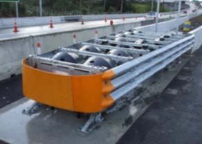
NZTA M23C 2017   |   4

OTHER CONSIDERATIONS

• Performance of the crash cushion may not be as intended if the water freezes. If conditions are below zero degrees, acceptable additives
  can be used to stop the water freezing.
• Appropriate machinery and safety equipment must be used to move ABSORB 350 elements when full.
• Drive-by system inspections are recommended at least monthly, and hands-on inspections are recommended at least yearly.
• All plastic crash cushions used to shield rigid or semi-rigid barriers can pose a significant hazard when struck at a steep angle near
  the transition. Under some impact conditions vehicles may penetrate and strike the barrier end or intrude a significant distance (over
  30m) into the shielded area. For this reason plastic crash cushions/terminals must not be installed on curves, or wide roads where steep
  angles of impact are more likely.
• The temporary crash cushion must not be installed on curves or wide roads where steep angles of impact are more likely.
• When installed on concrete barrier, the temporary crash cushion must only be attached using the approved proprietary
  transition attachment.
• When installed on steel barrier, the temporary crash cushion must only be attached using the approved proprietary transition
  attachment for the steel barrier system and the final lengths of steel barrier must be pinned or fixed to the road surface in accordance
  with the System Supplier’s specifications.

NOTES :
NZTA M23C 2017 | 5
ACZ-350 TEMPORARY CRASH CUSHION
SUMMARY
SUPPLIER: Ingal Civil (NZ) (http://www.ingalcivil.co.nz/default.html)
TEST LEVEL / CONDITIONS: TL2 and TL3. NCHRP-350 TL-2 and TL-3
PRODUCT MANUAL click for product manual download
FOR USE WITH Temporary concrete barrier installations. This system is NOT allowed to be used with temporary
steel barrier systems.
The ACZ-350 is a portable crash cushion accepted for use in construction zones where the chance of high speed, high angle impacts has
been assessed to be low. This system has been tested using the NCHRP 350 crash test protocol.
The ACZ-350 System is designed to perform as a narrow, non-redirecting crash cushion to shield the blunt ends of temporary
concrete barrier.
Impacting vehicles are brought to a safe and controlled stop when the System is struck on the nose within design limits. The ACZ-350
System absorbs impact energy and cushions vehicular impacts while significantly reducing the risk to occupants of the impacting vehicle.
The system consists of a sheet metal nose, four water-filled plastic shell segments, and a steel transition pinned together to act as an
end treatment.
The system provides several advantages including being lightweight, Economical, having a narrow profile and quick and easy deployment.
TECHNICAL INFORMATION
DIMENSIONS 9.6m length unit
600mm width, 800mm height
WEIGHT 612kg (empty)
2794kg (full)
TOTAL LENGTH 9.6m for TL-3
GRADE OR PLACEMENT Not to be placed on crossfalls greater than 5% or longitudinal slopes greater than 5%.
RESTRICTIONS
Clear Zone 6m x 22.5m clear zone to enable the system to gate if hit downstream from the head
OTHER RESTRICTIONS There must be sufficient free space for recovery behind the terminal should the vehicle strike the terminal
/ CONSIDERATIONS laterally and pass through.
The terminal is only to be installed where it is likely to be struck head on.
The terminal must not be installed on curves or wide roads where steep angles of impact are more likely.
The terminal must only be attached using the approved proprietary transition attachment.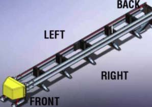
NZTA M23C 2017   |   6

OTHER CONSIDERATIONS

• The terminal must contain the correct number of segments required for the test level appropriate for the situation.
• The ACZ-350 System is capable of handling impacts from vehicles up to 2000 kg at speeds up to 100 km/h at angles up to 20°.
• All plastic crash cushions used to shield rigid or semi-rigid barriers can pose a significant hazard when struck at a steep angle near
  the transition. Under some impact conditions vehicles may penetrate and strike the barrier end or intrude a significant distance (over
  30m) into the shielded area. For this reason plastic crash cushions/terminals must not be installed on curves, or wide roads where steep
  angles of impact are more likely.
• The existence of cross slopes greater than 5%, longitudinal slope greater than 5%, or curbs may create a vaulting effect on the
  impacting vehicle.
• The ACZ-350 System will only perform properly if the water ballast is NOT allowed to freeze. Depending on anticipated climate
  conditions, an appropriate antifreeze agent may need to be selected and added in appropriate quantities to each water-filled segment to
  prevent freezing.
• Visual drive-by inspections are often all that is required. Special inspection considerations include the amount of water in the sections,
  how properly aligned the segments are and checks for any water leakage in the surrounding area.
• If the drive-by inspection indicates maintenance is required, then a walk-up inspection is necessary.
• Post impact review includes the inspection for defects in each barrier, the nose, the attaching concrete barrier, the transition and all steel
  straps, pins and stiffeners.

NOTES :
NZTA M23C 2017 | 7
ARMORZONE TL2 PLASTIC BARRIER + AMORZONE END TREATMENT
SUMMARY
SUPPLIER: CSP Pacific (http://www.csppacific.co.nz/)
TEST LEVEL / CONDITIONS: TL2. NCHRP-350 TL-2
PRODUCT MANUAL click for product manual download
ArmorZone TL-2 Plastic Barrier a 100% polyethylene water filled barrier (no steel reinforcement) to have been judged to have satisfied the
evaluation criteria of NCHRP 350 Test Level 2 (TL-2). The polyethylene composition, profile design and steel pin connector allow the barrier
to be installed straight or curved.
ArmorZone TL-2 Plastic Barrier made up of plastic units that are joined together using a steel pin connector and filled with water.
This provides a positive work zone barrier protection to temporary construction sites and other miscellaneous roadside activities.
The ArmorZone End Treatment is a free standing ‘special’ end unit that can be fitted to the barrier in a tangent position if required. If this end
treatment is not used the barrier will need to be flared.
In-service impact deflection in excess of the test values indicated below must be allowed for in any temporary traffic management plan
utilising the ArmorZone TL-2 Plastic Barrier System. All relevant minimum requirements of CoPTTM in regard to working spaces and safety
zones must be met irrespective of the variant in use, in particular the test level of the system must meet or exceed the test level required for
the operating speed of the adjacent traffic (refer CoPTTM B12.1).
TECHNICAL INFORMATION
DIMENSIONS 2m length unit
450mm width (base)
WEIGHT 50kg (empty), 550kg (filled)
MINIMUM LENGTH 50m
(2 End Treatments and 23 units)
LENGTH OF NEED 16m (8 units)
MINIMUM RADIUS 28m
CLEAR ZONE 2.1m behind the barrier
6m x 22.5m clear zone for the end treatment to enable the system to gate if hit downstream from the head
GRADE OR PLACEMENT A maximum approach and cross slope of 1V:10H is preferable. On slopes greater than this approval
RESTRICTIONS is required from the road controlling authority.
Do not install in front, behind or on a curb. Approval is required from the road controlling
authority otherwise.NZTA M23C 2017 | 8
DEFLECTION 2.1m from rear edge of barrier (70km/h, 2000kg vehicle, 25° angle)
WATER FILL HOLE DIAMETER 125mm
WATER FILL CAPACITY 520L
OTHER RESTRICTIONS / All units must be connected with the appropriate steel connecting pin and filled with water when
CONSIDERATIONS in use.
The adjacent road operating speed must be limited to 70km/h and the installation should
endeavour to minimise the impact angles to 25° (1 lateral: 2.14 forward).
The ArmorZone TL2 End Treatment forms an integral part of this system and MUST be installed
and maintained in accordance with the product installation/maintenance manual and relevant NZ
Transport Agency specifications.
Should the end treatment component of this system NOT be fitted, the barrier system will be
considered non-conformant with the Interim Acceptance notice.
Site specific grading may be necessary to ensure that there are no “humps” or “hollows” that may
significantly alter the impacting vehicles stability or substantially alter the barrier height in relation
to the ground.
OTHER CONSIDERATIONS
• ArmorZone is a stand-alone barrier and does not require at any stage during installation that the surrounding soil be dug or drilled
in anyway.
• ArmorZone barrier can be used in both “roadside’ and ‘median’ applications.
• It is recommended ArmorZone systems be installed on a compacted surface.
• There are no tools required to install the components of ArmorZone. The units can be manually lifted and positioned by two personnel
• Ensure that sufficient width and traffic control is available before installing ArmorZone.
• Depending on location, delineation may be required as per the Road Controlling Authority Guidelines.
NOTES :NZTA M23C 2017 | 9
BARRIERGUARD 800 STEEL BARRIER SYSTEM
SUMMARY
SUPPLIER: Highway Care (http://www.highwaycare.co.uk)
TEST LEVEL / CONDITIONS: TL-2, Tl-3 & TL-4 NCHRP 350. TL-3 MASH.
PRODUCT MANUAL click for product manual download
The BarrierGuard 800 Steel Barrier System is a temporary steel barrier system comprising 6m or 12m sections fabricated from galvanised steel
panels joined using a proprietary connection system, terminating with ground anchored end sections protected by the use of a crash cushion.
BarrierGuard 800 is a deformable vehicle restraint system acting as a continuous beam, anchored to the ground at the end of each run through
specially designed terminal sections.
The barrier system is used as a temporary barrier for road construction sites where it can be used for nearside or offside applications to protect
construction sites and construction workforce as a positive form of protection. It can also be used as a positive separation for opposing traffic
flows in a contra-flow situation.
With the versatile shorter barrier sections and radius sections most vertical and horizontal curve alignments can be accommodated so
BarrierGuard 800 is just as useful for the local roads as well as on the State Highway network.
In-service impact deflection in excess of the test values indicated below must be allowed for in any temporary traffic management plan
utilising the BarrierGuard 800 Steel Barrier System (non-MDS variants). All relevant minimum requirements of CoPTTM in regard to
working spaces and safety zones must be met irrespective of the variant in use, in particular the test level of the system must meet or exceed
the test level required for the operating speed of the adjacent traffic (refer CoPTTM B12.1).
TECHNICAL INFORMATION
DIMENSIONS 6m or 12m length per unit
540mm width (base), 235mm (top)
800mm height
WEIGHT 1080kg (12m unit)
MINIMUM LENGTH 18m with no approved crash cushion connected to the end terminal
60m including end terminals
GRADE OR PLACEMENT Not to be installed on ground of cross slope greater than 8% (1V:8H). On slopes greater than this,
RESTRICTIONS approval is required from the road controlling authority.NZTA M23C 2017 | 10
DEFLECTION STANDARD SYSTEM (60M BETWEEN ANCHORS)
1.36m at 70Km/h (NCHRP 350 - 2000P at 25°)
1.60m at 100Km/h (NCHRP 350 - 2000P at 25°)
1.74m at 80Km/h (NCHRP 350 - 8000T at 15°)
1.70m at 100Km/h (MASH 2270P at 25°)
LDS SYSTEM (12M BETWEEN ANCHORS)
0.89m at 100Km/h (NCHRP 350 - 2000P at 25°)
0.42m at 80Km/h (NCHRP 350 - 8000t at 15°)
MDS SYSTEM (6M BETWEEN ANCHORS)
0.076m at toe of barrier 100Km/h (NCHRP 350 - 2000P at 25°)
OTHER RESTRICTIONS / A selection of 0.61m long radius sections are available (typically 5° & 10°). These enable installations
CONSIDERATIONS around tight radii.
If the installation of the BarrierGuard 800 is not able to be flared as per the manual then there must
be an approved NCHRP 350 TL-3 crash cushion connected to the barrier with a clear zone area of
6 x 22.5m adjacent to the crash cushion and behind the barrier that is flat and without hazards. In
addition workers, equipment and materials should be a minimum of 6m behind the barrier.
Depending on location, delineation may be required as per the Road Controlling Authority Guidelines.
BarrierGuard 800 can be installed to a surface which is raised by a curb of no more than 100mm
high. If the barrier is installed next to the curb you must ensure that the curb is out of the clear zone
and does not prevent the barrier deflecting as intended.
OTHER CONSIDERATIONS
• The BarrierGuard 800 system has been designed to attach to concrete or asphalt foundations, or anchored into soil.
• BarrierGuard 800 is available in three configurations: Standard System, Limited Deflection System (LDS) and Minimum Deflection
System (MDS). The MDS requires the addition of steel ‘T-Top’ sections on top of the barrier and must have site specific sign off by the
Lead Advisor Safety (Roads & Roadsides)..
• Site specific grading may be necessary to ensure that there are no “humps” or “hollows”.
• It is recommended that the system is installed on a compacted surface.
• The final section at both ends of any BarrierGuard 800 Steel Barrier System installation must be anchored to the pavement in
accordance with the System Supplier’s instructions.
• The maximum spacing between anchor points is 60m to replicate crash test deflections (this may be waived in special circumstances
subject to acceptance in writing to the Lead Advisor Safety (Roads & Roadsides).
• Debris and foreign objects should not be in the clear zone.
• Where a BarrierGuard 800 “Gate” unit is to be installed (max gate length =30m), intermediate anchorage of the up and downstream
sections of standard BarrierGuard must be installed.
• BarrierGuard 800 Steel Barrier System must have one of the following accepted crash cushion installed for protection at both ends:
ABSORB 350
SLED-Euro
Quadguard CZ
SCI-100 Smart Cushion
Tau-II
NOTES :NZTA M23C 2017 | 11
SLED CRASH CUSHION (EURO-TERMINAL)
SUMMARY
SUPPLIER: RTL (http://www.rtl.co.nz/)
TEST LEVEL / CONDITIONS: TL2 and TL3. NCHRP-350 TL-2 and TL-3
PRODUCT MANUAL click for product manual download
FOR USE WITH Concrete or steel barriers
The SLED-EURO temporary crash cushion is a narrow, water-filled, non-redirective, gating crash cushion. It is designed to shield the end of
permanent and portable barriers made of concrete or steel. The SLED-EURO End Treatment System is designed for uni– and bi-directional
traffic flow applications. The SLED EURO-TERMINAL variant utilises the same cartridge system as the SLED-US however employs steel
lateral panels and inter-cartridge steel frames to increase lateral integrity and thus improve side impact redirection over the SLED-US variant.
As shown in the figure above, the TL-3 SLED-EURO End Treatment System consists of three water-filled and one empty plastic module to
decelerate an impacting vehicle to meet TL-3 crashworthy requirements of Report NCHRP 350. Attached to the front empty module is the
patented Containment Impact Sled (CIS) which collects the ruptured debris in front of the impacting vehicle. TL-3 SLED End Treatment
System consists of three water filled plastic modules, and a CIS attached to the front of an empty module.
TECHNICAL INFORMATION
DIMENSIONS Module: 1924mm length unit, 571mm width, 1084mm height
CIS: 2247mm length, 681mm width, 1166mm height
WEIGHT Module: 72.6kg (empty), 907kg (full)
CIS: 89.36kg
LENGTH 7.92m
WATER FILL CAPACITY 832L per module
WATER FILL HOLE DIAMETER 203.2mm
CLEAR ZONE 6m x 22.5m clear zone to enable the system to gate if hit downstream from the head
GRADE OR PLACEMENT The maximum cross slope or approach slope the End Treatment may be used on is 1 in 10. On slopes
RESTRICTIONS greater than this approval is required from the road controlling authority.
OTHER RESTRICTIONS / The terminal is only to be installed where it is likely to be struck head on.
CONSIDERATIONS The Yellow CIS module is NOT filled with water.
The SLED-EURO End Treatment must not be attached or anchored to the ground.NZTA M23C 2017 | 12 OTHER CONSIDERATIONS • The minimum acceptable configuration for use on >70km/h State highway sites is the 4 module TL3 configuration. • Modules can be stacked only when empty and are not designed to be stacked on each other when filled. • If the temperature at the SLED site is expected to be at or below the freezing point of water 0°C, it is recommended that an additive be used to lower the freezing point (salt additive). • There must be sufficient free space for recovery behind the terminal should the vehicle strike the terminal laterally and pass through. • All plastic crash cushions used to shield rigid or semi-rigid barriers can pose a significant hazard when struck at a steep angle near the transition. Under some impact conditions vehicles may penetrate and strike the barrier end or intrude a significant distance (over 30m) into the shielded area. For this reason plastic crash cushions/terminals must not be installed on curves, or wide roads where steep angles of impact are more likely. • When installed, the terminal must only be attached using the approved transition attachment. • When installed as an end treatment, the terminal must be attached using the approved T-pin and T-pin clip. NOTES :
NZTA M23C 2017 | 13
SLED CRASH CUSHION (SLED-US)
SUMMARY
SUPPLIER: RTL (http://www.rtl.co.nz/)
TEST LEVEL / CONDITIONS: TL2 and TL3. NCHRP-350 TL-2 and TL-3
PRODUCT MANUAL click for product manual download
FOR USE WITH The Sentry Water Cable Barrier System ONLY (Page 26)
The SLED temporary crash cushion is a narrow, water-filled, non-redirective, gating crash cushion. It is designed to shield the end of plastic
water filled barrier systems - specifically the Sentry Water cable Barrier System. The SLED End Treatment System is designed for uni– and bi-
directional traffic flow applications. The SLED-US End Treatment system differs from the SLED-EURO in that it does not employ steel lateral
panels to the rear two cartridges.
As shown in the figure above, the TL-3 SLED End Treatment System consists of three water-filled and one empty plastic module to decelerate
an impacting vehicle to meet TL-3 crashworthy requirements of Report NCHRP 350. Attached to the front empty module is the patented
Containment Impact Sled (CIS) which collects the ruptured debris in front of the impacting vehicle. TL-3 SLED End Treatment System
consists of three water filled plastic modules, and a CIS attached to the front of an empty module.
TECHNICAL INFORMATION
DIMENSIONS Module: 1924mm length unit, 571mm width, 1084mm height
CIS: 2247mm length, 681mm width, 1166mm height
WEIGHT Module: 72.6kg (empty), 907kg (full)
CIS: 89.36kg
LENGTH 7.92m
WATER FILL CAPACITY 832L per module
WATER FILL HOLE DIAMETER 203.2mm
CLEAR ZONE 6m x 22.5m clear zone to enable the system to gate if hit downstream from the head
GRADE OR PLACEMENT The maximum cross slope or approach slope the End Treatment may be used on is 1 in 10. On slopes
RESTRICTIONS greater than this approval is required from the road controlling authority.
OTHER RESTRICTIONS / The terminal is only to be installed where it is likely to be struck head on.
CONSIDERATIONS The Yellow CIS module is NOT filled with water.
The SLED End Treatment must not be attached or anchored to the ground.NZTA M23C 2017 | 14 OTHER CONSIDERATIONS • The minimum acceptable configuration for use on >70km/h State highway sites is the 4 module TL3 configuration. • Modules can be stacked only when empty and are not designed to be stacked on each other when filled. • If the temperature at the SLED site is expected to be at or below the freezing point of water 0°C, it is recommended that an additive be used to lower the freezing point (salt additive). • There must be sufficient free space for recovery behind the terminal should the vehicle strike the terminal laterally and pass through. • All plastic crash cushions used to shield semi-rigid barriers can pose a significant hazard when struck at a steep angle near the transition. Under some impact conditions vehicles may penetrate and strike the barrier end or intrude a significant distance (over 30m) into the shielded area. For this reason plastic crash cushions/terminals must not be installed on curves, or wide roads where steep angles of impact are more likely. • When installed, the terminal must only be attached using the approved transition attachment. • When installed as an end treatment, the terminal must be attached using the approved T-pin and T-pin clip. NOTES :
NZTA M23C 2017 | 15
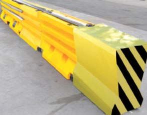
J-J HOOKS® CONCRETE BARRIER SYSTEM
SUMMARY
SUPPLIER: Tauren Barriers Ltd. (www.taurenbarriers.co.nz)
TEST LEVEL / CONDITIONS: TL3. NCHRP-350 TL-3 (March 1999)
PRODUCT MANUAL click for product manual download
*current as at 24 Dec 2013. Tauren Barriers. Contact supplier for up-to-date manual
FOR USE WITH TL-3 F-shape barrier profile only (not new jersey shape). Compliant end treatment and/or suitable
barrier flare in accordance with CoPTTM
The J-J Hooks® concrete barrier joint system has FHWA approval and has been used in New Zealand as connection system for temporary concrete
barrier units for temporary traffic management barrier systems for over 17 years.
This barrier system, like most temporary systems, relies on ribbon strength (connection of continuous strings of barriers) to generate absorbsion
and redirection capability. The J-J Hook connections between barriers are key to this ribbon strength and they must be in good condition and
robustly linked. Full contact with the road surface is also key as the friction of the barrier on the road is important for the function of the system.
This system does not require pinning or anchoring to the road surface.
In-service impact deflection in excess of the test values indicated below must be allowed for in any temporary traffic management plan
utilising the JJ-Hooks Barrier System. All relevant minimum requirements of CoPTTM in regard to working spaces and safety zones must be
met irrespective of the variant in use, in particular the test level of the system must meet or exceed the test level required for the operating
speed of the adjacent traffic (refer CoPTTM B12.1).
TECHNICAL INFORMATION
DIMENSIONS 3.6m length unit OR 6m length unit.
606mm width (base), 810mm height
NOTE: 3.6m and 6m units can be used together interchangeably without any restrictions
WEIGHT 2400kg (3.6m unit), 4300kg (6m unit)
MINIMUM LENGTH 43.2m minimum total length continuous string
(12 x 3.6m units or 8 x 6m units)
MINIMUM RADIUS 3.6m units – 30m horizontal radius, 30m vertical radius (sag curve), 53m vertical radius (crest curve)
GRADE OR PLACEMENT Not to be placed oncrossfall of 6% or greater.
RESTRICTIONS
Not to be placed on unstable (mud, un-compacted sand) ground or a surface where the full underside
surface of the barrier is not in contact with the road surface).
Barrier rotation – 7° lateral per section, 4° vertical per section.
DEFLECTION 1.2m from rear edge of barrier (100km/h, 2000kg vehicle, 25° angle)
FLARE RATE 10V:1H maximum (for the system).
NOTE: CoPTTM may require much shallower flare rates based on conditions or situation)NZTA M23C 2017 | 16
OTHER RESTRICTIONS / Not to be placed on, directly in front, or directly behind a kerb. (if in front - deflection zone must be
CONSIDERATIONS present behind. Behind kerb – minimum 3m rearward offset).
Ensure safe and correct lifting and manoeuvring of barriers is undertaken. Barrier size and weight
means heavy machinery/plant is required. Ensure product manual and expert advice is sought for
installation/removal.
Can be fitted with sight screens (on the non-traffic side). Refer to product manual.
OTHER CONSIDERATIONS
• J-J Hook® connections can be damaged during installation and removal and bent. Pre-inspection of these is important and concerns
over J-J Hook® condition should result in that barrier not being used. Removal of the J-J Hook® and re-welding or retro-fitting
is prohibited.
• Any exposed blunt end of the barrier system must be protected if it can be struck. Either an end terminal is required or the blunt end must
be flared away from the approach direction of traffic beyond the clear zone.
NOTE: Flaring the blunt end beyond the clear zone this does not necessarily protect the end from being struck. Site specific analysis and consideration
is required.
• If an end terminal is fitted, it must be connected to the end of the barrier with an approved proprietary connection that is designed for use
with the f-shape barrier and with the utilised end terminal.
• If the barrier system is utilised in conjunction or association with another barrier system (either semi-rigid, rigid or flexible) then site-
specific design and consideration is required (i.e. connection of temporary systems to permanent guardrail installations).
• Delineation is required with this system in the form of retro-reflective orange/black chevrons placed at 10m spacing on the top of the
barriers. This includes the end terminal (if fitted).
• Barriers must be natural concrete or galvanised in colour. The barrier units may be painted orange to increase conspicuity if desired.
• Some transitions will provide a JJ transition component - if supplied it must be used.
NOTES :NZTA M23C 2017 | 17
QUADGUARD II BARRIER SYSTEM
SUMMARY
SUPPLIER: Ingal Civil (http://www.ingalcivil.co.nz/default.html)
TEST LEVEL / CONDITIONS: TL1, TL2 and TL3. NCHRP-350 TL-1 & TL-2 & TL3
PRODUCT MANUAL click for product manual download
The QuadGuard II is a potentially reusable, redirective, non-gating crash cushion for hazards ranging in width from 610 mm to 3200 mm.
It consists of energy-absorbing cartridges surrounded by a framework of Quad-Beam Panels.
The 5 bay QuadGuard II System has successfully passed the NCHRP 350, Test Level 3 tests with both the light car and pickup truck at speeds up
to 100 km/h (62 mph) at angles up to 20 degrees.
During head-on impacts, the QuadGuard II System telescopes rearward and crushes to absorb the energy of impact. When impacted from the
side, it safely redirects the vehicle back toward its original travel path and away from the hazard.
A bay describes a section of the QuadGuard System consisting of an energy absorbing cartridge, a diaphragm, two fender panels and fasteners.
The QuadGuard System is capable of redirecting 820 to 2000 kg vehicles which impact the sides of the system at speeds up to 100 km/h at
angles of 20° for both right-way and wrong-way impacts. For head-on impacts into the nose, a QuadGuard is capable of meeting the occupant
risk criteria as recommended in NCHRP 350.
TECHNICAL INFORMATION
DIMENSIONS Available in seven widths:
610 mm, 760 mm, 915 mm, 1219 mm, 1755 mm, 2285 mm , 3200 mm
GRADE OR PLACEMENT Should be assembled only on an existing or freshly placed and cured concrete base
RESTRICTIONS (28 MPa minimum).
May be assembled on a non-reinforced concrete roadway (minimum 200 mm thick).
Cross-slope shall not exceed 8% and should not twist more than 2% over the length of the system.
The foundation surface shall have a light broom finish.
OTHER RESTRICTIONS / The system must be anchored.
CONSIDERATIONS As a general rule, selection of the narrowest width that adequately shields the hazard
is recommended.
System length is specified by the number of bays the system includes. The number of bays required is
a function of the design speed of the roadway, as specified in the product manual.
When there is an existing guardrail or median barrier at the site, the backup of the QuadGuard
System should tie into it when possible.NZTA M23C 2017 | 18 OTHER CONSIDERATIONS • Visual Drive-By Inspections are recommended at least once a month. Walk-Up Inspections are recommended at least once a year for QuadGuard II systems on asphalt. • Impacts in excess of TL-3 impact severity, or the existence (at the site of the installation) of curbs or cross slopes in excess of 8%, may yield crash performance which does not meet NCHRP 350 evaluation criteria. • The system can be pre-assembled away from the job site. When the need arises, the QuadGuard can be positioned at the impact site with the aid of a 2 ton lifting device. • QuadGuard II System is suitable for unfinished median barriers, bridge piers, temporary or permanent safety walls, light posts, or numerous other types of hazards. • The system must be inspected after each impact and must be pulled out to its original length. Depending on the impact, components may get damaged and need replacement. NOTES :
NZTA M23C 2017 | 19
RICOCHET TL2 PLASTIC BARRIER SYSTEM + RICOCHET TL2 END TREATMENT
SUMMARY
SUPPLIER: Advantage Plastics (http://www.advantageplastics.co.nz/)
TEST LEVEL / CONDITIONS: TL2
PRODUCT MANUAL click for product manual download
The Ricochet TL2 Safety Barrier and Terminal End is a rotational molded product manufactured from LHDPE (Linear High Density
Polyethylene) polymer.
These Barriers can be connected together by using the Ricochet galvanized pin to form a longitudinal straight or curved line for protection
and traffic flow direction for all road and construction sites and situations. Barriers are designed to be filled with water in accordance with the
TL2 MASH standard they are certified for.
The Ricochet Terminal End and Terminal End Cap are designed to connect directly to the Ricochet Safety Barrier to form ‘Terminal Ends’ at
each installed length of barrier which results in the certified ‘system’.
In-service impact deflection in excess of the test values indicated below must be allowed for in any temporary traffic management plan
utilising the Ricochet TL2 Safety Barrier System. All relevant minimum requirements of CoPTTM in regard to working spaces and safety
zones must be met irrespective of the variant in use, in particular the test level of the system must meet or exceed the test level required for
the operating speed of the adjacent traffic (refer CoPTTM B12.1).
TECHNICAL INFORMATION
DIMENSIONS 2000mm length (pin to pin length is 1700mm when inter-connected)
580mm width, 1020mm height
WEIGHT Barrier: 62kg (empty), 620kg (full)
Terminal end: 42kg
MINIMUM LENGTH 61m
(2 x end treatments (each 2 yellow sections + end cap) and 32 x orange barrier sections)
CLEAR ZONE 6m x 22.5m clear zone to enable the system to gate if hit downstream from the head
GRADE OR PLACEMENT Ground conditions must be of satisfactory compactness and levelness does not exceed 10%
RESTRICTIONS (1 vertical, 10 horizontal) for both longitudinal and cross slope.
Must not be installed on top of or in front of any curbs or channels
WATER FILL CAPACITY 600L for each barrier
DEFLECTION 3.5m (70km/h, 1100kg small car and 2270kb pick-up, 25° angle)NZTA M23C 2017 | 20
OTHER RESTRICTIONS / Terminal End units and Terminal End Barrier Caps (Yellow) must not contain water as they are
CONSIDERATIONS certified not to.
When assembling the Barrier System always have a clear working Zone of at least 2 metres on
either sides of the barrier
Lifting Barriers must be by mechanical methods and use the lifting provision slots as provided.
OTHER CONSIDERATIONS
• Should the end treatment component of this system not be fitted, the barrier system will be considered non-conformant.
• Apply antifreeze additives in the water when using in sub-zero conditions. Use antifreeze ratios as per System Supplier’s specifications.
• When filling barriers with water it is advisable to fill from the construction site side of the barrier.
• Once barriers are filled then position the chevrons into their appropriate positions. One chevron to be installed every fifth barrier.
• The contractor must ensure the ground is compacted and there are no humps or hollows.
• Every alternative working day the system must be checked for alignment, barrier continuity, damage and cracks.
• Repairs and adjustments must be made to alignment faults greater than 30mm within one hour of occurrence, or within one hour of
inspection, whichever allows the earliest remedial repairs to be undertaken.
• The Ricochet Barrier Cage Packs should be used when transporting the Ricochet Barrier System. These are a safe and efficient cage method of
transporting the product; they are also very useful for storage.
• The Ricochet Road Barrier System is covered by a 3 year warranty which covers the general wear & tear and performance of the product. Any
damage of the product must be reported to the seller within 3 days of occurrence.
NOTES :NZTA M23C 2017 | 21
SCI-100 SMART CUSHION
SUMMARY
SUPPLIER: Tauren Barriers Ltd. (http://www.taurenbarriers.co.nz)
TEST LEVEL / CONDITIONS: TL3
PRODUCT MANUAL click for product manual download
FOR USE WITH Permanent or temporary concrete barriers
The Smart Cushion Innovations (SCI) crash attenuator is a speed-dependent product that varies stopping resistance during an impact. The
Smart Cushion Innovations (SCI) crash attenuator allows lighter and slower-moving vehicles to have longer ride-down distances. This system is
fully redirective, non-gating and bi-directional.
SCI-100GM SMART CUSHION crash cushion ion was successfully tested as a concrete barrier end terminal system under the NCHRP 350
protocol for Test Level 3 (100 km/h).
TECHNICAL INFORMATION
DIMENSIONS TL2: 4m long, 609.6mm wide, 863.6mm high
TL3: 6.55m long, 609.6mm wide, 863.6mm high
WEIGHT TL2: 1120.4kg (for attenuators only)
TL3: 1564.9kg (for attenuators only)
GRADE OR PLACEMENT Foundations must be a flat surface with longitudinal and cross slopes of 10V:1H or less.
RESTRICTIONS Smart Cushion impact units should not be located over drainage basins or expansion joints.
Asphaltic concrete foundation pads are appropriate for work zone installations.
OTHER RESTRICTIONS / Smart Cushion system should not be placed directly behind raised curbs.
CONSIDERATIONS Smart Cushion system should be connected to barriers that are as high as or higher than the
cushion to provide proper support and attachment.
Smart Cushion allows for connection to many barrier shapes. A rectangular concrete block provides
the most economical and simplest shape to connect to.
Foundation concrete should reach full cure strength before use (28MPa minimum).
The SCI can be bolted onto a concrete pad and inserted into a rebated seal area and work
independent of a barrier string. The SCI is also approved to be pinned to the seal. Refer to manual
for specifications.NZTA M23C 2017 | 22 OTHER CONSIDERATIONS • SCI attenuators come fully assembled for a pick-and-set install. The units require no backstops for permanent or temporary construction applications. • The system provides very low impact forces on the vehicle’s occupants and a reduced risk of injury occurrence and severity. • Check to make sure there are no drains; expansion joints; or buried cables and utility lines in the footprint space where the units will be placed. Remove any curbs or obstacles in front of or beside where the units will be installed for a minimum distance of 12ft from any edge of the unit. • Be sure to set up proper traffic control before beginning any installation or repair work at the site. • Prior to installing the crash cushion on an existing foundation, the concrete must be thoroughly inspected for slope, signs of cracking, surface wear, shifting from original position or any other sign of deterioration. If any of these signs are evident, the foundation must be removed and a new one must be installed. • The crash cushion is shipped in one piece, fully assembled. • Installation of the front delineation plate will be determined by the location of the attenuator and road authority regulations. NOTES :
NZTA M23C 2017   |   23

SENTRY WATER-CABLE BARRIER SYSTEM

 SUMMARY

 SUPPLIER:                             RTL       (http://www.rtl.co.nz)

 TEST LEVEL / CONDITIONS:              TL2 and TL3. NCHRP-350 TL-2 and TL-3

 PRODUCT MANUAL                        click for product manual download

 FOR USE WITH                          The SLED-US (page16) water-filled, non-redirective, gating crash cushion is the ONLY crash cushion
                                       currently accepted as an end protection

The Sentry Water-Cable Barrier is a plastic, water-filled portable longitudinal barrier used to provide positive protection in the work zone.
The Sentry Water-Cable Barrier utilizes water dispersion upon impact in combination with internal molded-in steel cables. Upon impact,
the plastic container ruptures and disperses the contained water. Simultaneously, the internal cables provide the strength to safely catch the
misguided vehicle like a net, preventing vehicle intrusion into the work zone.
The Sentry is designed to form a series of individual sections linked together to function as a portable longitudinal barrier to keep vehicles
from penetrating the linked barrier sections. The Sentry provides positive separation from the vehicles on the roadway and workers in the
roadside work zone.
When an impacting vehicle contacts the Sentry Water-Cable Barrier, the water and internal molded in steel cables act together to re-direct
or bring the impacting vehicle to a controlled stop.
All Sentry Water-Cable Barrier sections should be orange in colour and contain internal molded-in steel cables. Any other colour, or product
without internal molded in cables, will not qualify as a Sentry Water-Cable Barrier product.

In-service impact deflection in excess of the test values indicated below must be allowed for in any temporary traffic management plan
utilising the Sentry Water-Cable Barrier System. All relevant minimum requirements of CoPTTM in regard to working spaces and safety
zones must be met irrespective of the variant in use, in particular the test level of the system must meet or exceed the test level required for
the operating speed of the adjacent traffic (refer CoPTTM B12.1).

 TECHNICAL INFORMATION

 DIMENSIONS                        1924mm length (pin to pin)
                                   571mm width , 1084mm height

 WEIGHT                            72.6kg (empty)
                                   907kg (full)

  MINIMUM LENGTH                   25 units (approximately 48m)

 MINIMUM RADIUS                    5.5m

 WATER FILL CAPACITY               832L

 WATER FILL HOLE SIZE              203mm

 GRADE OR PLACEMENT                The foundation is required to support the weight of the fully loaded
NZTA M23C 2017 | 24 RESTRICTIONS sections e.g. Concrete, asphalt, dirt and gravel. DEFLECTION 2.74m (62.5km/h, 2000kg vehicle, 25° angle) CLEAR ZONE 6m x 22.5m clear zone to enable the system to gate if hit downstream from the head OTHER RESTRICTIONS / There should be periodic checking of the water level to ensure that it is filled to the proper level. CONSIDERATIONS All units MUST be connected with the appropriate steel connecting pin and filled with water when in use. OTHER CONSIDERATIONS • Repairing a crack or hole does not return the plastic to its original strength, although most repairs are sufficient to insure a water tight section (the System Supplier’s product guidelines provide instructions on the viability of minor repairs). • In freezing weather conditions, allowing the water to freeze to a solid mass of ice should not be allowed. If the temperature at the site is expected to be at or below the freezing point of water, it is recommended that an additive be used. • Maximum dynamic deflection at point of impact shall not exceed 3.7 m when impacted at the design speed of TL-3 100 km/h utilizing the 2000 kg vehicle. • Both systems, Sentry and SLED, MUST be installed and maintained in accordance with their relevant product installation/maintenance manuals and relevant NZ Transport Agency specifications (including CoPTTM). • Should the SLED end treatment component NOT be fitted, the barrier system will be considered non-conformant. NOTES :
NZTA M23C 2017 | 25
TAU- II CRASH CUSHION SYSTEM
SUMMARY
SUPPLIER: CSP Pacific (http://www.csppacific.co.nz/)
TEST LEVEL / CONDITIONS: TL2 and TL3. NCHRP-350 TL-2 and TL-3
PRODUCT MANUAL click for product manual download
The TAU-II system has been tested to meet the requirements of NCHRP Report 350, Test Levels 2 and 3. The system is provided in lengths
and capacities for both low speed and high speed applications.
The TAU-II system is fully redirective and non-gating, and is ideally suited for narrow hazards such as the ends of rigid barriers, tollbooths,
utility poles and more. Ease of installation, numerous transition options, low maintenance requirements, and reusability of system
components make the TAU-II system ideal for treating many roadside hazards.
The TAU-II system is designed to shield the ends of median barriers and other narrow fixed objects likely to be struck head-on, by absorbing
and dissipating the energy of impacting vehicles. TAU-II utilises disposable Energy Absorbing Cartridges (EACs) to absorb the energy of the
impacting vehicle. As the vehicle compresses the cushion, it exerts a force on the first bay containing an EAC.
The TAU-II crash cushion can be installed with either a freestanding “Compact Backstop” or a “P.C.B. Backstop” that can be attached to
properly reinforced concrete barrier.
TECHNICAL INFORMATION
DIMENSIONS TL2: length: 4 bays. 3.78m (P.C.B Backstop) or 4.28m (Compact Backstop)
TL3: length: 8 bays. 7.25m (P.C.B Backstop) or 7.75m (Compact Backstop)
762mm width, 829mm height
GRADE OR PLACEMENT Cross slopes of up to 8% (5 degrees) can be accommodated with the standard hardware and with the
RESTRICTIONS instructions provided with the system. If there are cross slopes in excess of 8%, contact CSP Pacific to
obtain engineering advice and assistance.
OTHER RESTRICTIONS / The approved anchoring foundation configurations for the TAU-II system utilises a solid concrete
CONSIDERATIONS pad over the length of the system.
The concrete foundation must be a minimum of 150mm thick, reinforced 28 MPa Portland Cement
Concrete (PCC) or 200mm non-reinforced 28MPa PCC.
The foundation should be free of major cracks and other structures
All curbs, islands and elevated objects greater than 100mm high that would be beneath, beside or
less than 15m in front of a TAU-II crash cushion should be removed prior to installation.NZTA M23C 2017 | 26 OTHER CONSIDERATIONS • The frequency of Drive-By inspections is dependent on the traffic volume and the impact history of the system. Drive-By inspections are recommended at least monthly. • Hands-On inspections are recommended at least yearly. NOTES :
NZTA M23C 2017   |   27

TRACC CRASH ATTENUATION CUSHION

 SUMMARY

 SUPPLIER:                                Ingal Civil       (http://www.ingalcivil.co.nz)

 PRODUCT MANUAL                           click for product manual download

Crash cushions, also called impact attenuators, prevent errant vehicles from impacting a barrier or fixed object hazard either by gradually
decelerating the vehicle, or by redirecting the vehicle away from the hazard. They are ideally suited for terminating concrete barriers or for
use where longitudinal barriers would not be effective to shield objects.
The TRACC cushions are fully redirective, non-gating, bi-directional energy- absorbing, designed to protect motorists from impacting the end
of concrete barriers, toll plazas, bridge piers and other hazards in both temporary and permanent work zone locations.
Installation of the TRACC system and its transitions depends on the traffic pattern and the backup structure at the particular location.
Unidirectional traffic (one side or both) requires no transition provided the unit is installed beyond the clear zone of opposing traffic.
The WideTRACC offers various options in protecting wide hazards and gores. The WideTRACC can be flared down its right side only (R), its
left side only (L) or down both sides simultaneously (B).

 Configuration Options:

 System                               Test Level                          Width                                Length

 TRACC                                3                                   610mm                                6.5m

 ShorTRACC                            2                                   610mm                                4.3m

 FasTRACC                             3+*                                 610mm                                7.9m

 WideTRACC- B                         3                                   1470mm**                             6.5m**

 WideTRACC - L                        3                                   1040mm***                            6.5m***

 WideTRACC - R                        3                                   1040mm***                            6.5m***

* Test Level 3+ indicates that the FasTRACC has been crash tested at 110km/h which exceeds the normal Test Level 3 impact of 100km/h.
 ** The width of the WideTRACC – B can be further increased by adding wing extensions on both sides. The extensions will add 710mm of
length and 175mm of system width per extension added.
*** The width of the WideTRACC – L and – R can be further increased by adding wing extensions on one side. The extensions will add
710mm of length and 87mm of system width per extension added.
NZTA M23C 2017 | 28
TECHNICAL INFORMATION
GRADE OR PLACEMENT It is recommended that the TRACC system should not be placed directly behind a raised kerb. The
RESTRICTIONS approach area in front of the system should slope at a rate no greater than 10V:1H in the direction of traffic
flow. The cross slope should be no more than 12V:1H
OTHER RESTRICTIONS / The TRACC can be anchored to a combination of asphalt, concrete and compacted sub base.
CONSIDERATIONS TRACC units are supplied with four pieces of delineation tape that can be customised to create any of
three delineation designs .
A plastic nose cone that is supplied with the system should be attached to the front of the TRACC
TRACC units are delivered pre-assembled to site to facilitate rapid installation and minimise disruption
to traffic flow.
TRACC systems can be lifted as complete units.
Holes should be drilled 40mm less than the overall length of the anchor studs to ensure proper
embedment to the foundation.
OTHER CONSIDERATIONS
• Since TRACC systems are delivered fully assembled, the damaged system is replaced entirely with all repairs performed accurately in
the safety of the supplier’s workshop.
• Field repair is to be limited to minor end-on impacts that stroke the system less than 1350mm.
NOTES :NZTA M23C 2017 | 29
WATER-WALL TL1 PLASTIC BARRIER + MINI-SLED TL1 PLASTIC END TERMINAL
SUMMARY
SUPPLIER: CSP Pacific (http://www.csppacific.co.nz/)
TEST LEVEL / CONDITIONS: TL1. NCHRP-350 TL-1
PRODUCT MANUAL click for product manual download
The Water-Wall TL1 barrier system is a plastic, water-filled portable barrier used to provide positive protection in the work zone. It is
designed to form a series of individual sections linked together to function as a portable longitudinal barrier to keep vehicles from breaching
the linked barrier sections. When an impacting vehicle contacts the TL-1Water-Wall, it is brought to a controlled stop or redirected.
TL1 Water Wall has been tested in accordance with NCHRP Report 350 and complied with the required evaluation criteria for Test Level 1
(TL1). The FHWA issued a letter of acceptance B-130 (December 2004) for the use of the Water-Wall TL1 temporary barrier system.
The Mini-SLED temporary crash cushion system has been tested in accordance with MASH criteria and complied with the required
evaluation criteria for Test Level 1 (TL1).
Used together, in the configuration shown below, the Water-Wall temporary barrier and Mini-SLED end treatment comprise an NCHRP350
TL1 temporary barrier system.
In-service impact deflection in excess of the test values indicated below must be allowed for in any temporary traffic management plan
utilising the Water-Wall TL1 barrier system. All relevant minimum requirements of CoPTTM in regard to working spaces and safety zones
must be met irrespective of the variant in use, in particular the test level of the system must meet or exceed the test level required for the
operating speed of the adjacent traffic (refer CoPTTM B12.1).
TECHNICAL INFORMATION
DIMENSIONS 1960m length
460mm width, 822mm height
1854mm effective length
WEIGHT 35kg (empty)
500kg (full)
MINIMUM LENGTH 52.4m minimum total length
(2 x yellow Mini-SLED end treatments and 26 x orange Water-Wall barrier sections)
WATER FILL CAPACITY 465L per section
CLEAR ZONE 6m x 22.5m clear zone to enable the system to gate if hit downstream from the head
GRADE OR PLACEMENT End Treatment not to be placed on cross or approach slopes greater than 10°
RESTRICTIONS
MINIMUM DEFLECTION 2.44m from rear edge of barrier (50km/h, 2000kg vehicle, 25° angle)
LENGTH OF NEED Mini-SLED plus 7 Water-Wall barrier unitsYou can also read