GM-FA-10J Gate Monitoring Safety Module - 24V ac/dc operation, 1- or 2-Channel Input Original Instructions
←
→
Page content transcription
If your browser does not render page correctly, please read the page content below
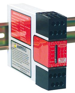
GM-FA-10J Gate Monitoring Safety Module
24V ac/dc operation, 1- or 2-Channel Input
Original Instructions

                                                             • Monitors one or two safety switches for a contact failure or wiring fault
                                                             • Two output switching channels for connection to control-reliable power in-
                                                               terrupt circuits
                                                             • Auto reset or monitored manual reset
                                                             • Design complies with standards UL991, ISO 14119, and ISO 13849-1
                                                               (EN954-1) (Safety Category 2, 3 or 4)
                                                             • For use in functional stop category 0 applications per NFPA 79 and IEC
                                                               60204-1
                                                             • 6 amp safety output contacts
                                                             • Plug-in terminal blocks
                                                             • If terminal blocks are swapped, Module remains functional with no loss of
                                                               safety function

Overview
The GM-FA-10J Gate Monitor Safety Module (the “Safety Module”) is used to verify the proper operation of coded magnetic safety
switches and positive-opening safety switches by monitoring a normally open (N.O.) and a normally closed (N.C.) contact from each
switch. It can also be used to monitor and verify the correct state of two redundant current-sourcing PNP signals. (One PNP source must
be Normally OFF and the other Normally Conducting for each input channel.) In a typical application, two safety switches (individually
mounted) indicate the open or closed status of a gate, moveable guard, or barrier (all called “guards” throughout this document).
Two functions of the Safety Module are:
    1. To monitor the contacts and wiring of safety switches for certain failures and to prevent the machine from restarting if the switch or
       the Module fails, and
    2. To provide a reset routine after closing the guard and returning the inputs to their “closed” condition. This reset function may be
       required by machine safety standards.
The Safety Module monitors each switch for complementary switching; each channel must have one open (OFF) input and one closed
(conducting) input at all times. These inputs must always be in opposite states and must switch state within 1 second of each other.
Channel 1 has a “guard closed” condition when S11/S13 is closed and S11/S12 is open. Similarly, Channel 2 has a “guard closed” condi-
tion when S21/S23 is closed and S21/S22 is open (see Figure 2. Wiring to two 4-wire coded magnetic safety switches on page 7 and
Figure 3. Wiring to two positive-opening safety interlock switches on page 7). The Safety Module also will detect and properly respond
to a short circuit between the channels and a short circuit to other sources of power. The Safety Module will open the safety outputs
within 35 milliseconds of the switching of either channel when the guard opens.
When the guard closes, debounce logic in the Safety Module’s inputs increases the reliability and repeatability of successfully resetting
the Safety Module and reduces the necessity of re-cycling the guard. This feature can result in increased efficiency of the machine, even
if the guard is misaligned or vibration is present.
Important: Read This First!
The user is responsible for satisfying all local, state, and national laws, rules, codes, and regulations relating to the use of this
product and its application. Banner Engineering Corp. has made every effort to provide complete application, installation, operation, and
maintenance instructions. Please direct any questions regarding the use or installation of this product to the factory applications depart-
ment at the telephone numbers or address found at http://www.bannerengineering.com.
The user is responsible for making sure that all machine operators, maintenance personnel, electricians, and supervisors are thorough-
ly familiar with and understand all instructions regarding the installation, maintenance, and use of this product, and with the machinery it
controls. The user and any personnel involved with the installation and use of this product must be thoroughly familiar with all applicable
standards, some of which are listed within the specifications. Banner Engineering Corp. makes no claim regarding a specific recommen-
dation of any organization, the accuracy or effectiveness of any information provided, or the appropriateness of the provided information
for a specific application.

P/N 060998 Rev. F                                                  2/8/2013

                                                                                                                              0 060998    2
GM-FA-10J Gate Monitoring Safety Module Applicable U.S. Standards ANSI B11 Standards for Machine Tools Safety Contact: Safety Director, AMT – The Association for Manufacturing Technology, 7901 Westpark Drive, McLean, VA 22102, Tel.: 703-893-2900 ANSI NFPA 79 Electrical Standard for Industrial Machinery Contact: National Fire Protection Association, 1 Batterymarch Park, P.O. Box 9101, Quincy, MA 02269-9101, Tel.: 800-344-3555 ANSI/RIA R15.06 Safety Requirements for Industrial Robots and Robot Systems Contact: Robotic Industries Association, 900 Victors Way, P.O. Box 3724, Ann Arbor, MI 48106, Tel.: 734-994-6088 Applicable International Standards ISO 12100-1 & -2 (EN 292-1 & -2) Safety of Machinery – Basic Concepts, General Principles for Design IEC 60204-1 Electrical Equipment of Machines Part 1: General Requirements ISO 13849-1 (EN 954-1) Safety-Related Parts of Control Systems ISO 13855 (EN 999) The Positioning of Protective Equipment in Respect to Approach Speeds of Parts of the Human Body ISO 14119 (EN 1088) Interlocking Devices Associated with Guards – Principles for Design and Selection Also, request a type “C” standard for your specific machinery. Contact: Global Engineering Documents, 15 Inverness Way East, Englewood, CO 80112-5704, Tel.: 800-854- 7179 Certificate of Adequacy This Safety Module datasheet (p/n 60998) satisfies the requirements of Machinery Directive 2006/42/EC, Section 1.7.4 — instructions. Safety Circuit Integrity and ISO 13849-1 (EN954-1) Safety Circuit Principles Safety circuits involve the safety-related functions of a machine that minimize the level of risk of harm. These safety-related functions can prevent initiation, or they can stop or remove a hazard. The failure of a safety-related function or its associated safety circuit may result in an increased risk of harm. The integrity of a safety circuit depends on several factors, including fault tolerance, risk reduction, reliable and well-tried components, well-tried safety principles, and other design considerations. Depending on the level of risk associated with the machine or its operation, an appropriate level of safety circuit performance must be incorporated into its design. Standards that detail safety performance levels include ANSI/RIA R15.06 Industrial Robots, ANSI B11 Ma- chine Tools, OSHA 29CFR1910.217 Mechanical Power Presses, and ISO 13849-1 (EN954-1) Safety-Related Parts of a Control System. Safety Circuit Integrity Levels Safety circuits in International and European standards have been segmented into categories, depending on their ability to maintain their integrity in the event of a failure. The most recognized standard that details safety circuit integrity levels is ISO 13849-1 (EN954-1), which establishes five levels: Categories B, 1, 2, 3, and the most stringent, Category 4. In the United States, the typical level of safety circuit integrity has been called ”control reliability.” Control reliability typically incorporates redundant control and self-checking circuitry and has been loosely equated to ISO 13849-1 Categories 3 and 4 (see CSA Z432 and ANSI B11.TR4). If the requirements described by ISO 13849-1 (EN954-1) are to be implemented, a risk assessment must first be performed to determine the appropriate category, in order to ensure that the expected risk reduction is achieved. This risk assessment must also take into ac- count national regulations, such as U.S. control reliability or European “C” level standards, to ensure that the minimum level of perform- ance that has been mandated is complied with. Fault Exclusion An important concept within the category requirements of ISO 13849-1 is the probability of the occurrence of the failure, which can be decreased using the "fault exclusion" method. This method assumes that the possibility of certain well-defined failure(s) can be reduced to a point where the resulting fault(s) can be disregarded. Fault exclusion is a tool a designer can use during the development of the safety-related part of the control system and the risk assess- ment process. It allows the designer to eliminate the possibility of various failures and justify it through the risk assessment process to meet the requirements of Categories 2, 3 or 4. See ISO 13849-1/-2 for further information. 2 www.bannerengineering.com - tel: 763-544-3164 P/N 060998 Rev. F
GM-FA-10J Gate Monitoring Safety Module

Configuration
                                              The Safety Module may be configured via DIP switches for two-channel (redundant
                               S12 S11 S13
                                              switches on a single guard), or one-channel operation (individual switches on two
                                              guards). In two-channel operation, each channel must switch within 3-second si-
                             A1 13 23 Y1      multaneity of the other when the guard closes. If not, the guard must be re-opened
                                              and closed until the timing requirement is met. When the guard opens, the two
              Power ON       S21      S11
                                              channels
                                               S13
                                                         operate concurrently (both channels must switch, but without the timing
                                              requirement).
                                    13    23     Y1
                 (green)    A1
                           Power
              Fault (red)
                  Input 1
                            Fault
                                              In one-channel operation, each channel operates individually, except to reset the
                                                  K1

          Active (green)     In 1                 K2

                             In 2
                                              device (in which case both guards must be closed). If only one switch is being
                                          14 24

                  Input 2
                                              monitored,  the closed input of the unused channel must be jumpered (S11/S13 or
                                          Machine
                           Output          Safety
          Active (green)                 GM-FA-10J

                                              S21/S23).
                            Y2      14    24     A2
                 Outputs     S23      S21      S22
          Active (green)
                                              The reset function has two options, selected by DIP switch: Automatic reset or
                             Y2 14 24 A2
                                              Monitored Manual reset. See Figure 7. Wiring to the guarded machine on page
                                              9 for configuration information.
                               S23 S21 S22
                                              The reset input also can be used for an External Device Monitoring (EDM) circuit.
                                              The EDM circuit consists of a normally closed, force-guided contact from each de-
                                              vice being controlled by the Safety Module, all wired in series with the Reset button
Figure 1. GM-FA-10J Features and Terminal Lo-
                                              (if used) and terminated at terminals Y1 and Y2. See Figure 6. Alternate wiring for
                          cations
                                              two-channel monitoring of multiple guards on page 8 for further information.
                                              The output of the Safety Module consists of two redundant output switching chan-
                                              nels, each of which is the series connection of two forced-guided relay contacts
                                              (K1 and K2 in Figure 6. Alternate wiring for two-channel monitoring of multiple
                                              guards on page 8). Each of the switching outputs is rated for up to 250V ac at
                                              up to 6 amps.

                     WARNING: Hazard Point
                     It must not be possible for personnel to reach any hazard point through an opened guard (or any
                     opening) before hazardous machine motion has completely stopped.
                     Please reference OSHA CFR 1910.217 and ANSI B11 standards for information on determining safety
                     distances and safe opening sizes for your guarding devices.

                     WARNING: Safety Categories
                     The level of safety circuit integrity can be greatly impacted by the design and installation of the safety
                     devices and the means of interfacing of those devices. A risk assessment must be performed to deter-
                     mine the appropriate safety circuit integrity level or safety category as described by ISO 13849-1
                     (EN 954-1) to ensure that the expected risk reduction is achieved and that all relevant regulations
                     and standards are complied with.

Safety Interlock Switch Requirements
The following general requirements and considerations apply to the installation of interlocked guards and gates for the purpose of safe-
guarding. In addition, the user must refer to the relevant regulations to be sure to comply with all necessary requirements.
Hazards guarded by the interlocked guard must be prevented from operating until the guard is closed; a stop command must be issued to
the guarded machine if the guard opens while the hazard is present. Closing the guard must not, by itself, initiate hazardous motion; a
separate procedure must be required to initiate the motion. The safety switches must not be used as a mechanical or end-of-travel stop.
The guard must be located an adequate distance from the danger zone (so that the hazard has time to stop before the guard is opened
sufficiently to provide access to the hazard), and it must open either laterally or away from the hazard, not into the safeguarded area. The
guard also should not be able to close by itself and activate the interlocking circuitry. In addition, the installation must prevent personnel
from reaching over, under, around or through the guard to the hazard. Any openings in the guard must not allow access to the hazard

P/N 060998 Rev. F                                      www.bannerengineering.com - tel: 763-544-3164                                        3
GM-FA-10J Gate Monitoring Safety Module
(see OSHA 29CFR1910.217 Table O-10, ANSI B11.19, ISO 13857, ISO14120/EN953 or the appropriate standard). The guard must be
strong enough to contain hazards within the guarded area, which may be ejected, dropped or emitted by the machine.
The safety interlocking switches, actuators, sensors, and magnets must be designed and installed so that they cannot be easily defeated.
They must be mounted securely, so that their physical position cannot shift, using reliable fasteners that require a tool to remove them.
Mounting slots in the housings are for initial adjustment only; final mounting holes must be used for permanent location.
WARNING: Perimeter Guarding Applications
If the application could result in a pass-through hazard (for example, perimeter guarding), either the safe-
guarding device or the guarded machine's MSCs/MPCEs must cause a Latched response following a Stop
command (for example, interruption of the sensing field of a light curtain, or opening of an interlocked gate/
guard). The reset of this Latched condition may only be achieved by actuating a reset switch that is sepa-
rate from the normal means of machine cycle initiation. The switch must be positioned as described in this
document.
Lockout/Tagout procedures per ANSI Z244.1 may be required, or additional safeguarding, as described by
ANSI B11 safety requirements or other appropriate standards, must be used if a passthrough hazard can-
not be eliminated or reduced to an acceptable level of risk. Failure to observe this warning could result
in serious bodily injury or death.
Coded Magnetic Safety Switches
Similar to positive-opening safety switches, coded magnetic switches used with the Safety Module must provide one normally closed
contact and one normally open contact (typically a four-wire switch). The sensor and its magnet must be mounted a minimum distance of
15 mm (0.6 inches) from any magnetized or ferrous materials for proper operation. If either the sensor or magnet is mounted on a materi-
al that can be magnetized (a ferrous metal, such as iron), the switching distance will be affected. Although the sensor and magnet are
coded to minimize the possibility of false actuation, they should not be used within known fields of high-level electromagnetic radiation.
Depending on the model of sensor and magnet used, the installation must be designed to provide the correct direction of approach. The
speed of approach must be fast enough to meet the simultaneity-monitoring period of 1.0 second, approximately equal to or greater than
0.1 m (4 inches) per second. If the simultaneity requirement is not met, the Safety Module can not be reset and will not close its safety
output contacts.
Positive-Opening Interlocking Switches
Safety interlock switches used with the Safety Module must satisfy several requirements. Each switch must provide electrically isolated
contacts: at minimum, one normally closed (N.C.) contact or normally conducting source and one normally open (N.O.) contact or normal-
ly OFF source to interface with the Module.
The contacts must be of “positive-opening” design, with one or more normally closed contacts rated for safety. Positive-opening operation
causes the switch to be forced open, without the use of springs, when the switch actuator is disengaged or moved from its home position
(see the Banner Catalog for examples). In addition, the switches must be mounted in a “positive mode,” to move/disengage the actuator
from its home position and open the normally closed contact, when the guard opens.
Switch Hookups, Typical Applications
Requirements vary widely for the level of control reliability or safety category (per ISO 13849) in the application of interlocked guards.
Although Banner Engineering always recommends the highest level of safety in any application, it is the responsibility of the user to
safely install, operate, and maintain each safety system and comply with all relevant laws and regulations. The applications shown in
Figure 2. Wiring to two 4-wire coded magnetic safety switches on page 7 through Figure 4. Wiring to two complementary current-
sourcing PNP devices on page 7 meet or exceed the requirements for control reliability and Safety Category 3 or 4, per ISO 13849
(EN954-1).
Mechanical Installation
The Safety Module must be installed inside an enclosure.
It is not designed for exposed wiring. It is the user’s responsibility to house the Safety Module in an enclosure with NEMA 3 (IEC IP54)
rating, or better. The Safety Module mounts directly to standard 35 mm DIN rail.
Heat Dissipation Considerations. For reliable operation, ensure that the operating specifications are not exceeded. The enclosure must
provide adequate heat dissipation, so that the air closely surrounding the Module does not exceed the maximum operating temperature
stated in the Specifications. Methods to reduce heat build-up include venting, forced airflow (e.g., exhaust fans), adequate enclosure
exterior surface area, and spacing between modules and other sources of heat.
4 www.bannerengineering.com - tel: 763-544-3164 P/N 060998 Rev. FGM-FA-10J Gate Monitoring Safety Module
Electrical Installation
Each Safety Module is powered by 24V ac/dc (at less than 150 mA). The Safety Module, in turn, supplies power to each switch.
It is not possible to give exact wiring instructions for a Safety Module that interfaces to a multitude of machine control configurations. The
following guidelines are general in nature.
The Safety Module has no delay function. Its output relay contacts open within 35 milliseconds after a safety input opens. This classifies
the Safety Module as a functional stop "Category 0" control, as defined by ANSI NFPA 79 and IEC/EN 60204-1.
WARNING: Shock Hazard and Hazardous Energy
Always disconnect power from the safety system (for example, device, module, interfacing, etc.)
and the machine being controlled before making any connections or replacing any component.
Electrical installation and wiring must be made by Qualified Personnel and must comply with the relevant
electrical standards and wiring codes, such as the NEC (National Electrical Code), ANSI NFPA79, or IEC
60204-1, and all applicable local standards and codes.
Lockout/tagout procedures may be required. Refer to OSHA 29CFR1910.147, ANSI Z244-1, ISO
14118, or the appropriate standard for controlling hazardous energy.
Connection of Power to the Safety Module
The Safety Module requires a 24V ac/dc supply voltage (see Specifications). Use extreme caution whenever installing ac power. Use a
minimum of 16 to 18 AWG wire for power and output connections. Use a minimum of 20 AWG wire for all other terminal connections. A
hand-operated supply disconnect and over-current protection (e.g., a circuit breaker) must be provided per ANSI NFPA79 and IEC/
EN60204-1.
See Figure 2. Wiring to two 4-wire coded magnetic safety switches on page 7 through Figure 6. Alternate wiring for two-channel
monitoring of multiple guards on page 8 for connection of safety switches.
Monitoring Series-Connected Safety Switches
When monitoring two individually mounted safety switches (as shown in Figure 2. Wiring to two 4-wire coded magnetic safety switches on
page 7 through Figure 4. Wiring to two complementary current-sourcing PNP devices on page 7), a faulty switch will be detected if
it fails to switch as the guard opens. In this case, the Gate Monitor Module will de-energize its output relays and disable its reset function
until the input requirements are met (i.e., the faulty switch is replaced). However, when a series of interlocking safety switches is moni-
tored by a single Safety Module, the failure of one switch in the system may be masked or not detected at all (refer to Figure 5. Alternate
wiring for one-channel monitoring of multiple guards on page 8 and Figure 6. Alternate wiring for two-channel monitoring of multiple
guards on page 8).
Series-connected interlock switch circuits do not meet ISO 13849 (EN954-1) Safety Category 4 and may not meet Control Reliability
requirements because of the potential for an inappropriate Gate Monitor reset or a potential loss of the safety stop signal. A multiple
connection of this type should not be used in applications where loss of the safety stop signal or an inappropriate reset can lead potential-
ly to serious injury or death. The following two scenarios assume two positive-opening safety switches on each guard:
1. Masking of a failure. If a guard is opened but a switch fails to open, the redundant safety switch will open and cause the Safety
Module to de-energize its outputs. If the faulty guard is then closed, both Safety Module input channels also close, but because one
channel did not open, the Safety Module will not reset. However, if the faulty switch is not replaced and a second “good” guard is
cycled (opening and then closing both of the Module’s input channels), the Module considers the failure to be corrected. With the
input requirements apparently satisfied, the Module allows a reset. This system is no longer redundant and, if the second switch
fails, may result in an unsafe condition (i.e., the accumulation of faults results in the loss of the safety function).
2. Non-detection of a failure. If a good guard is opened, the Safety Module de-energizes its outputs (a normal response). But if a
faulty guard is then opened and closed before the good guard is re-closed, the failure on the faulty guard is not detected. This
system is no longer redundant and may result in a loss of safety if the second safety switch fails to switch when needed.
The systems in either scenario do not inherently comply with the safety standard requirements of detecting single faults and preventing
the next cycle. In multiple-guard systems using series-connected safety switches, it is important to periodically check the functional integ-
rity of each interlocked guard individually. Operators, maintenance personnel, and others associated with the operation of the machine
must be trained to recognize such failures and be instructed to correct them immediately.
Open and close each guard separately while verifying that the Gate Monitor outputs operate correctly throughout the check procedure.
Follow each gate closure with a manual reset, if needed. If a contact set fails, the Safety Module will not enable its reset function. If the
Safety Module does not reset, a switch may have failed; that switch must be immediately replaced.
P/N 060998 Rev. F www.bannerengineering.com - tel: 763-544-3164 5GM-FA-10J Gate Monitoring Safety Module
This check must be performed and all faults must be cleared, at a minimum, during periodic checkouts. If the application can not exclude
these types of failures and such a failure could result in serious injury or death, then the series connection of safety switches must not be
used.
WARNING: Multiple Switching Devices
Whenever two or more devices are connected to the same safety module (controller):
• Contacts of the corresponding pole of each switch must be connected together in series. Never
connect the contacts of multiple switches in parallel. Such a parallel connection defeats the switch
contact monitoring ability of the Module and creates an unsafe condition which could result in serious
injury or death.
• Each device must be individually actuated (engaged), then released (or re-armed) and the safe-
ty module reset. This allows the module to check each switch and its wiring to detect faults.
This check must be performed during the prescribed checkouts. Failure to test each device individually
in this manner could result in undetected faults and create an unsafe condition which could result
in serious injury or death.
Connection to the Guarded Machine
The machine interface hookup diagram (Figure 7) shows a generic connection of the Module’s two redundant output circuits to machine
primary control elements MPCE1 and MPCE2. A machine primary control element is an electrically powered device, external to the Mod-
ule, which stops the guarded machinery by immediately removing electrical power to the machine and (when necessary) by applying
braking to dangerous motion. The stop is accomplished by removing power to the actuator coil of either MPCE.
To satisfy the Safety Category 4 requirements of ISO 13849 (EN 954-1), each MPCE must offer a normally closed, forced-guided monitor
contact. One normally closed monitor contact from each MPCE is wired in series to the Y1-Y2 feedback/reset input (see Figure 7. Wiring
to the guarded machine on page 9). In operation, if one of the switching contacts of either MPCE fails in the shorted condition, the
associated monitor contact will remain open, preventing the reset of the Module.
External Device Monitoring
To satisfy the requirements of Control Reliability (OSHA and ANSI) and Category 3 and 4 of ISO 13849-1 (EN 954-1), the machine
primary control elements (MPCEs) must each offer a normally closed, forced-guided (mechanically linked) monitor contact. Connect one
normally closed monitor contact from each master stop control element in series to Y1 and Y2 (see hookup drawings).
In operation, if one of the switching contacts of either MPCE fails in the energized condition, the associated monitor contact will remain
open. Therefore, it will not be possible to reset the Safety Module. If no MPCE-monitor contacts are monitored, a jumper must be instal-
led between terminals Y1 and Y2 (dotted line), as shown in the hookup drawings. It is the user’s responsibility to ensure that any single
failure will not result in a hazardous condition and will prevent a successive machine cycle.
One-Channel Monitoring Two-Channel Monitoring
Configured for one-channel monitoring of either one or two guards. Configured for two-channel monitoring of one guard. This applica-
This application is considered to meet or exceed requirements for tion is considered to meet or exceed requirements for Control Reli-
Control Reliability and Safety Categories 3 and 4 per ISO 13849-1 ability and Safety Categories 3 and 4 per ISO 13849-1 (EN954-1).
(EN954-1).
6 www.bannerengineering.com - tel: 763-544-3164 P/N 060998 Rev. FGM-FA-10J Gate Monitoring Safety Module
One-Channel Monitoring Two-Channel Monitoring
Mechanical stop
Guard #1
open
Mechanical
Blue S12 S11 S13 stop
Guard #1
Gray
Black
Brown
S12 S11 S13
SI-MAG..SM SI-MAG..MM
S23 S21 S22
Mechanical
NOTE: If only one magnetic safety switch stop Guard
open
is used, select 1-channel input and
jumper S23 to S21.
NOTE: Guard shown in closed position.
Guard #2
S23 S21 S22 open Figure 3. Wiring to two positive-opening safety interlock
Blue switches
Gray
Black
Brown
SI-MAG..SM SI-MAG..MM
Mechanical stop
Figure 2. Wiring to two 4-wire coded magnetic safety switches
+24V dc
N.O.
+24V dc N.C.
S12 S13 0V
A1
NOTE: If PNP current-sourcing signals
are used, the GM-FA-10J and the
current-sourcing devices must be
powered from the same DC supply
and Common (Com).
A2
S23 S22 +24V dc
0V
N.O.
N.C.
0V
Figure 4. Wiring to two complementary current-sourcing PNP
devices
P/N 060998 Rev. F www.bannerengineering.com - tel: 763-544-3164 7GM-FA-10J Gate Monitoring Safety Module
One-Channel Monitoring
Configured for one-channel monitoring of multiple guards with sin- Guard #1 Guard #2 Guard #n
gle switches at each guard (see Warning). Up to 10 Banner mag- SI-MAG..MM SI-MAG..MM SI-MAG..MM
netic switches may be connected to each channel in this series/ SI-MAG..SM SI-MAG..SM SI-MAG..SM
parallel method.
Gray
Gray
Gray
Blue
Blue
Blue
Black
Black
Black
Brown
Brown
Brown
Mechanical
WARNING: stop
Not a Safety Category 4 Appli-
cation.
S12 S11 S13 NOTE: Switch/magnet pairs
When monitoring multiple guards shown in closed position.
with a series connection of multi-
ple safety interlock switches, a
single failure may be masked or
not detected at all. S23 S21 S22
When such a configuration is
used, procedures must be per-
formed regularly to verify proper
Brown
Brown
Brown
Black
Black
Black
Gray
Gray
Gray
Blue
Blue
Blue
operation of each switch. See Mechanical
“Monitoring Series- Connected stop
SI-MAG..SM SI-MAG..SM SI-MAG..SM
Safety Switches” for more infor- SI-MAG..MM SI-MAG..MM SI-MAG..MM
mation. Guard #3 Guard #4 Guard #n+1
Figure 5. Alternate wiring for one-channel monitoring of multi-
(If other than Banner magnetic switches are used, a total resist- ple guards
ance of 270 Ohms between S11/S13, S11/S12, S21/S22 and
S21/S23 must not be exceeded.)
Two-Channel Monitoring
Configured for two-channel monitoring of multiple guards with two Guard #1 Guard #2 Guard #3 Guard #4 Guard #n
safety switches mounted individually on each guard (see Warning).
The number of mechanical switches is limited by the max. resist-
ance of 270 ohm between S11/S13, S11/S12, S21/S22 and S21/
S23. The total resistance is calculated by adding the resistance of
all guard switch contacts and the resistance of the cables that con-
nect the switches and the switches to the module. S12 S11 S13
NOTE: Guards shown in closed position.
S23 S21 S22
Figure 6. Alternate wiring for two-channel monitoring of multi-
ple guards
WARNING:
Not a Safety Category 4 Application.
When monitoring multiple guards with a series connection of multiple safety interlock switches, a single
failure may be masked or not detected at all.
When such a configuration is used, procedures must be performed regularly to verify proper operation of
each switch. See “Monitoring Series- Connected Safety Switches” for more information.
8 www.bannerengineering.com - tel: 763-544-3164 P/N 060998 Rev. FGM-FA-10J Gate Monitoring Safety Module
WARNING:
Interfacing MPCEs.
NEVER wire an intermediate device(s) (e.g., PLC, PES, PC), between the Safety Module outputs and the
machine primary control element (MPCE) it switches, in such a manner that in the event of a failure there
is the loss of the safety stop command, OR in such a manner that the safety function can be suspended,
overridden, or dereated, unless accomplished with the same or greater degree of safety. Whenever
forced-guided, mechanically linked relays are added as intermediate switching devices, a normally closed
forced-guided monitor contact from each relay must be added to the series feedback loop between Safety
Module terminals Y1 and Y2.
WARNING: Wiring of Arc Suppres-
MACHINE
sors CONTROL
If arc suppressors are used, they 24V ac/dc
MUST be installed as shown across RESET
the actuator coil of the stop control el-
ements (MSCs or MPCEs). NEVER S12 S11 S13
install suppressors directly across A1 13 23 Y1
the output contacts of the Safety For Automatic Reset,
Device or Module. It is possible for connect directly and
configure DIP switches
suppressors to fail as a short circuit. If K1
installed directly across the output
contacts, a short-circuited suppres- K2
sor will create an unsafe condition
which could result in serious injury Y2 14 24 A2
or death. S23 S21 S22
0V ac/dc
MPCE2 * MPCE2
Monitoring Contacts
or Jumper
* MPCE1 MPCE1
* Arc Suppressor, see Warning
Figure 7. Wiring to the guarded machine
Overvoltage Category II and III Installations (EN 50178 and IEC 60664-1)
The Safety Module is rated for Overvoltage Category III when voltages of 1V to 150V ac/dc are applied to the output relay contacts. It is
rated for Overvoltage Category II when voltages of 151V to 250V ac/dc are applied to the output relay contacts and no additional precau-
tions are taken to attenuate possible overvoltage situations in the supply voltage. The Module can be used in an Overvoltage Category III
environment (with voltages of 151V to 250V ac/dc) if care is taken either to reduce the level of electrical disturbances seen by the Module
to Overvoltage Category II levels by installing surge suppressor devices (e.g., arc suppressors), or to install extra external insulation in
order to isolate both the Safety Module and the user from the higher voltage levels of a Category III environment.
For Overvoltage Category III installations with applied voltages from 151V to 250V ac/dc applied to the output contact(s): the
Safety Module may be used under the conditions of a higher overvoltage category where appropriate overvoltage reduction is provided.
Appropriate methods include:
• An overvoltage protective device
• A transformer with isolated windings
• A distribution system with multiple branch circuits (capable of diverting energy of surges)
• A capacitance capable of absorbing energy of surges
P/N 060998 Rev. F www.bannerengineering.com - tel: 763-544-3164 9GM-FA-10J Gate Monitoring Safety Module
• A resistance or similar damping device capable of dissipating the energy of surges
When switching inductive ac loads, it is good practice to protect the Safety Module outputs by installing appropriately-sized arc suppres-
sors. However, if arc suppressors are used, they must be installed across the load being switched (e. g., across the coils of external
safety relays), and never across the Safety Module’s output contacts (see WARNING, Arc Suppressors).
Configuration
WARNING: Reset Routine Required
U.S. and international standards require that a reset routine be performed after clearing the cause of a
stop condition (for example, arming an E-stop button, closing an interlocked guard, etc.). Allowing the
machine to restart without actuating the normal start command/device can create an unsafe condi-
tion which could result in serious injury or death.
WARNING: Reset Switch Location
All reset switches must be accessible only from outside, and in full view of, the hazardous area.
Reset switches must also be out of reach from within the safeguarded space, and must be protec-
ted against unauthorized or inadvertent operation (for example, through the use of rings or guards). If
any areas are not visible from the reset switch(es), additional means of safeguarding must be provided.
Failure to do so could result in serious bodily injury or death.
Manual Reset and Reset Switch Connection
The reset switch must be capable of reliably switching 15 to 30V dc at 5 to 50 mA. As
shown in Figure 7. Wiring to the guarded machine on page 9, the reset switch connects DIP ON OFF
Switch
between terminals Y1 and Y2 of the Module. The reset switch must be located outside of – Bank "A"
S1.1
and not accessible from – the area of dangerous motion, and it must be positioned so the S1.2
switch operator can see all areas of dangerous motion during the reset procedure (see S21 S11 S13
Warning). A1
Power
13 23 Y1
Shown
with
To configure the Module for Manual Reset, set switches S1.2 and S2.2 in banks A and B to
Fault K1
In 1 K2 terminal
blocks
OFF. The reset switch may be any mechanical normally open switch, but should be a mo- In 2
14 24
Machine
Safety
removed
mentary switch or a two-position keyed switch. To reset the Module, both guards must be
Output
GM-FA-10J
Y2 14 24 A2
S23 S21 S22
closed, at which time the output LED will flash (signaling that the reset switch must be cy- DIP
Switch
cled). This action is a monitored manual reset (open-closed-open), where the “closed” Bank "B"
S2.1
phase is approximately 0.25 to 2 seconds long. S2.2
S1.1/S2.1 OFF* – 2-Channel
ON – 1-Channel
S1.2/S2.2 OFF* – Manual Reset
ON – Auto Reset
* Factory Default
NOTE: Corresponding DIP switches
in Banks A and B must be set identically.
Figure 8. DIP switch configuration set-
tings for reset mode and 1- or 2-chan-
nel operation
Automatic Reset Mode
To configure the Module for Automatic Reset, set switches S1.2 and S2.2 in Banks A and B to ON. If no MPCE contacts are monitored,
install a jumper between terminals Y1 and Y2 (see Figure 7. Wiring to the guarded machine on page 9). The Safety Module will reset
(and its outputs will energize) as soon as the guards return to their closed position.
Automatic Reset is useful for some automated processes. However, if Automatic Reset is used, an alternate means must be provided to
prevent resumption of hazardous machine motion until an alternate reset procedure is performed. The alternate means must include a
10 www.bannerengineering.com - tel: 763-544-3164 P/N 060998 Rev. FGM-FA-10J Gate Monitoring Safety Module
Reset switch, located outside the area of dangerous motion, and positioned so that the switch operator can see all areas of dangerous
motion during the reset procedure.
1-Channel or 2-Channel Input
The Safety Module may be configured for 1-channel (“single channel”) or 2-channel (“dual channel”) operation by setting DIP switches
S1.1 and S2.1 in Banks A and B. In 1-channel operation (S1.1 and S2.1 – ON), the input channels function independently. The two
guards can be monitored individually, but both channels must be in the closed position for the Safety Module to be reset.
In 2-channel operation ( S1.1 and S2.1 – OFF) the input channels must function together. Both channels must switch within a 3-second
simultaneity of the other when the guard closes. If not, the guard must be re-opened and closed until the timing requirement is met. When
the guard opens, the channels function concurrently (both must open, but without the timing requirement).
In either configuration, the “closed” inputs of each channel must be closed before the Safety Module can be reset (continuity S11 to S13
and S21 to S23). If in 1-channel mode and monitoring only one switch, a jumper must be installed at the unused input (e.g., S21 to S23;
see Figure 2. Wiring to two 4-wire coded magnetic safety switches on page 7).
Initial Checkout Procedure
CAUTION: Disconnect Power Prior to Checkout
Before performing the initial checkout procedure, make certain all power is disconnected from the
machine to be controlled.
Dangerous voltages may be present along the Safety Module wiring barriers whenever power to the ma-
chine control elements is ON. Exercise extreme caution whenever machine control power is or may
be present. Always disconnect power to the machine control elements before opening the enclo-
sure housing of the Safety Module.
WARNING: Multiple Safety Devices
When two or more safety devices are used, each device must be individually actuated, causing a
STOP or open-contact condition, then reset/rearmed and the Safety Module reset (if using manual
reset mode). This allows the monitoring circuits to check each device and its wiring to detect faults. Fail-
ure to test each device individually in this manner could result in undetected faults and create an
unsafe condition which could result in serious injury or death.
To remove a terminal block, insert a small screwdriver into the slot as shown, and
pry to loosen.
When reinserting the block, take care to slide the dovetail on the terminal block into
the slot on the frame.
Figure 9. Removal of terminal blocks
1. Remove power from the machine primary control elements (MPCEs).
2. Close all monitored guards. If the Module is wired to 1-channel input, the second input (S21/S23 or S11/S13) must be jumpered if
unused.
3. Apply input power (only) to the Gate Monitor Module at terminals A1 and A2 (see Figure 7. Wiring to the guarded machine on page
9). The following LEDs should come ON: Power, Input 1, Input 2
If the Power LED comes ON, but either or both Input LEDs are not ON, disconnect input power and check the wiring of the connected
switch(es) and/or the jumper. Check if the jumper is installed correctly on the unused input. Return to step 2 after the cause of the
problem has been corrected.
P/N 060998 Rev. F www.bannerengineering.com - tel: 763-544-3164 11GM-FA-10J Gate Monitoring Safety Module
4. Step 4 varies, depending on how the module is configured.
Option Description
If the Module is set to 1- After the Power, Input 1, and Input 2 LEDs all are ON, open and close all connected guards one at a
channel operation time. When each individual guard opens, the corresponding Input LED must turn OFF, and when the
guard closes its LED must come ON again.
If the Module is set to 2- After the Power, Input 1, and Input 2 LEDs all are ON, open the guard; both switches must open
channel operation within 3 seconds, and both Input LEDs must turn OFF. If the red Fault LED comes ON, simultaneity
between the switches or within one switch (between its NO and NC contacts) was not met. Check all
wiring and the switches.
If the Module is set to Auto (Y1/Y2 closed and DIP switches set to Auto Reset), the output LED will come ON as soon as both
Reset Input LEDs are ON (output contacts 13/14 and 23/24 close).
If the Module is set to Man- The Output LED should come ON only if Input 1 and 2 LEDs are ON and the Reset button connec-
ual Monitored Reset ted to Y1 and Y2 went from open to closed and back to open position.
5. Repeat step 4 individually for each guard that is being monitored.
6. Close the guard. Apply power to the machine control elements and perform the Periodic Checks on page 12.
NOTE: Make sure that both Input 1 and 2 LEDs are ON only when ALL connected guards are closed. If the guards are closed and
the Input LEDs are OFF, the guard switches may be wired incorrectly, which could reset the Module inappropriately (safety output
contacts close as soon as one of the connected guards opens).
Do not continue operation until all checks are completed and all problems are corrected. See Do Not Use Machine Until System is Work-
ing Properly warning, and Repairs on page 19 and Troubleshooting on page 19 for further information.
Periodic Checks
WARNING: Do Not Use Machine Until System Is Working Properly
If all of these checks cannot be verified, do not attempt to use the safety system that includes the
Banner device and the guarded machine until the defect or problem has been corrected (see Trouble-
shooting). Attempts to use the guarded machine under such conditions could result in serious bod-
ily injury or death.
At each shift change or machine setup, a Designated Person* should perform the following checks on all safety switches:
1. Verify the switch, sensor, actuator, or magnet are not broken or damaged.
2. Check for good alignment between the switch and actuator or sensor and magnet.
3. Confirm the switches are not being used as an end-of-travel stop.
4. Correct any loosened mounting hardware.
5. Verify it is not possible to reach any hazard point through an opened guard (or any opening) before hazardous machine motion stops
completely.
6. Open and close each guard separately while verifying that the Gate Monitor outputs operate correctly throughout the check proce-
dure. Follow each gate closure with a manual reset, if needed. If a contact set fails, the Safety Module will not enable its reset func-
tion. If the Safety Module does not reset, a switch may have failed; that switch must be immediately replaced.
7. In addition, a Qualified Person* should perform the following on a periodic schedule (determined by the user, based upon the severity
of the environment and the frequency of switch actuations):
a) Inspect the electrical wiring for continuity and damage.
b) Confirm that the wiring conforms to the instructions given in this installation manual.
Do not continue operation until all checks are completed and all problems are corrected. See Repairs on page 19 and Troubleshooting
on page 19 for further information.
* A Designated Person is identified in writing by the employer as being appropriately trained to perform a specified checkout procedure. A
Qualified Person possesses a recognized degree or certificate or has extensive knowledge, training, and experience to be able to solve
problems relating to safety switch installation.
12 www.bannerengineering.com - tel: 763-544-3164 P/N 060998 Rev. FGM-FA-10J Gate Monitoring Safety Module
Specifications
Power General
Supply Voltage and Current Pollution Degree
24V dc ±15% @ 150 mA (SELV-rated supply accord- 2
ing to EN IEC 60950, NEC Class 2) Status Indicators
24V ac ±15% @ 150 mA, 50-60 Hz +/- 5% (NEC Class 1 red LED: Fault (see Troubleshooting on page 19)
2-rated transformer) 4 green LEDs: Power – power is supplied to Safety
Power consumption: approx. 3 VA / 3 W Module; Channel 1 – inputs satisfied (guard closed);
To comply with UL and CSA standards, the isolated Channel 2 – inputs satisfied (guard closed); Output –
secondary power supply circuit in the installation must K1 and K2 energized, safety outputs closed
incorporate a method to limit the overvoltage to 0.8 kV. Construction
Supply Protection Circuitry Polycarbonate housing. Rated IEC IP20
Protected against transient voltages and reverse polari- Mounting
ty Mounts to standard 35 mm DIN rail track. Safety Mod-
Overvoltage Category ule must be installed inside an enclosure rated NEMA
Output relay contact voltage of 1V to 150V ac/dc: Cate- 3 (IEC IP54), or better.
gory III
Output relay contact voltage of 151V to 250V ac/dc:
Category II (Category III, if appropriate overvoltage re-
duction is provided, as described on Overvoltage Cat II
and III)
Outputs
Each normally open output channel is a series connection of con- Mechanical life
tacts from two forced-guided (mechanically linked) relays, K1-K2. ≥ 50,000,000 operations
Output Configuration Electrical life (switching cycles of the output contacts,
Contacts: AgNi, 5 μm gold-plated resistive load)
Low Current Rating: The 5 μm gold-plated contacts al- 150,000 cycles @ 900 VA
low the switching of low current/low voltage. In these 1,000,000 cycles @ 250 VA
low-power applications, multiple contacts can also be 2,000,000 cycles @ 150 VA
switched in series (e.g., “dry switching”). 5,000,000 cycles @ 100 VA
To preserve the gold plating on the contacts, do not ex- NOTE: Transient suppression is recommended when switching in-
ceed the following max. values at any time: ductive loads. Install suppressors across load. Never install sup-
Min. voltage: 1V ac/dc; Max. voltage: 60V pressors across output contacts (see Warning in Overvoltage Cat
Min. current: 5 mA ac/dc; Max. current: 300 mA II and III).
Min. power: 5 mW (5 mVA); Max. power: 7 W (7 VA) Output Response Time
High Current Rating 35 ms max.
If higher loads must be switched through one or more
of the contacts, the minimum and maximum values of
the contact(s) changes to:
UL Listed: Min voltage: 15V ac/dc; Min current: 30 mA
ac/dc; Min power: 0.45 W (0.45 VA); Max: 250V ac /
24V dc, 6 A resistive - B300, R300 per UL508
CE: Min voltage: 15V ac/dc; Min current: 30 mA ac/dc;
Min power: 0.45 W (0.45 VA); Max: 250V ac / 24V dc,
6 A resistive - IEC 60947-5-1: AC15: 230V ac, 3 A;
DC-13: 24V dc, 2 A
Inputs
Input Requirements Simultaneity Monitoring
2-Channel operation: 3 seconds
P/N 060998 Rev. F www.bannerengineering.com - tel: 763-544-3164 13GM-FA-10J Gate Monitoring Safety Module
Inputs
Each switch or sensor must have a normally closed 1-Channel operation: infinite
contact and a normally open contact capable of switch-
ing 20 to 50 mA @ 15 to 30V dc.
Reset switch: 20 mA @ 12V dc, hard contact only
Max. external resistance between terminals S11/S12,
S11/S13, S21/S22 and S21/S23: 270 ohms each.Max.
external resistance between terminals S11/S12, S11/
S13, S21/S22 and S21/S23: 270 ohms each.
Environmental Certifications
Vibration Resistance Design Standards
10 to 55 Hz @ 0.35 mm displacement per IEC CE: Cat. 4 PL e, per EN ISO 13849-1; SIL 3 per IEC
60068-2-6 61508 and IEC 62061
Operating Conditions
Temperature: 0° to +50°C (+32° to 122°F)
Maximum Relative Humidity: 90% @ +50°C (non-con-
densing)
Dimensions
22.5 mm
(0.89")
118.0 mm
(4.65")
S12 S11 S13
A1 13 23 Y1
Power
Fault K1 84.0 mm
K2
(3.31")
In 1
In 2
14 24
Machine
Output Safety
GM-FA-10I
Y2 14 24 A2
S23 S21 S22
Figure 10. Dimensions
Figure 11. Label
Magnetic Switch Models
14 www.bannerengineering.com - tel: 763-544-3164 P/N 060998 Rev. FGM-FA-10J Gate Monitoring Safety Module
Switching Distance
Magnet/Sensor Pair Magnet Sensor* Coded Magnet Sensor Cable
Min. ON Max. OFF
SI-MAG1MM 3 mm (0.12 in- 14 mm (0.55
SI-MAG1MM90†† ches) inches)
SI-MAG1SM
SI-MAG1SMCO† 8 mm (0.31 in- 16 mm (0.63
SI-MAG1MMHF
ches) inches)
3 m (10 ft) 4 mm (0.16 in- 8 mm (0.32 in-
SI-MAG2SM SI-MAG2MM
ches) ches)
3 mm (0.12 in- 7 mm (0.28 in-
SI-MAG3SM SI-MAG3MM
ches) ches)
* 9 m (30 ft) cables are available for magnet sensors by adding suffix “w/30” to the model number (e.g., SI-MAG1SM w/30).
† Cable opposite see Figure 13. SI-MAG1SMCO Sensor on page 16)
†† 90° orientation (see Direction of Approach for SI-MAG1xx Sensor/Magnet Pairs on page 17)
Magnetic Switch Specifications
Switching Elements Connections
Three pole-stable reed switches Integral PVC-jacketed 3 m (10 ft) 4-wire cable.
Repeat Switching Accuracy Cable O.D. is 5 mm (0.2 inches).
±0.1 mm (±0.004 inches) Wires are 24 AWG (0.25 mm²).
Construction Hardware
Epoxy-encapsulated circuit in polyamide housing All mounting hardware is supplied by user. Use of per-
Environmental Rating manent fasteners or locking hardware is recommended
NEMA 4X, IEC IP67 to prevent loosening or displacement of the actuator
Switching Capacity and switch body. Mounting holes in the magnet and
30V dc max @ 0.25W (27 Ω fuse resistor in-line, each sensor accept M4 (#6) hardware (see Magnetic Switch
channel) Dimensions on page 16).
Operating Temperature Application Note
–5° to +70°C (+23° to +158°F) The sensor/magnet pair must be mounted a minimum
distance of 15 mm (0.6 inches) from any magnetized or
ferrous materials. Multiple SFA-IMB1 (used with SI-
MAG1xx) and SFA-IMB2 (used with SI-MAG2xx) can
be used as spacers.
P/N 060998 Rev. F www.bannerengineering.com - tel: 763-544-3164 15GM-FA-10J Gate Monitoring Safety Module
Magnetic Switch Dimensions
25 mm
(0.98")
10.7 mm
(0.42") 25 mm
6.5 mm
(0.98")
(0.26") 7.2 mm 13 mm 10.7 mm
(0.28") (0.51") (0.42")
4.5 mm 6.5 mm
(0.18") (3) 2.5 mm 3.0 mm (0.26") 7.2 mm 13 mm
(0.10") (0.12") 78 mm (0.28") (0.51")
(3.07") Sensing 4.5 mm
Surface (0.18") (3) 2.5 mm 3.0 mm
88 mm (0.10") (0.12")
78 mm 68 mm
(3.07") Sensing (3.46")
(2.68")
Surface
88 mm 78 mm
68 mm (3.07") Magnet
(3.46")
(2.68") Surface
2.5 mm 3.0 mm 88 mm
4.5 mm 68 mm
(0.10") (0.12") (3.46")
(0.18") (3) (2.68")
7.2 mm 13 mm
6.5 mm (0.28") (0.51")
(0.26") 10.7 mm
(0.42")
25 mm
(0.98")
Figure 14. SI-MAG1MM/MM90/MMHF
Figure 12. SI-MAG1SM Sensor Figure 13. SI-MAG1SMCO Sensor Magnet
Sensing
Magnet Surface
Surface
ø 8.3 mm ø 8.3 mm
7 mm 7 mm (0.33") (2)
(0.33") (2) (0.28")
(0.28")
26 mm 26 mm
(1.02") (1.02")
ø 4.3 mm ø 4.3 mm
(0.17") (2) (0.17") (2)
22 mm 4.5 mm 22 mm 4.5 mm
(0.87") (0.18") (0.87") (0.18")
29 mm 29 mm
13 mm 13 mm
(1.14") (1.14")
(0.51") (0.51")
43 mm 43 mm
(1.69") (1.69")
Figure 15. SI-MAG2SM Sensor Figure 16. SI-MAG2MM Magnet
Sensing 35 mm
Surface (1.38") 10.5 mm
(0.41")
Magnet
34 mm
(1.34") Surface 4.5 mm
(0.18")
2 mm
(0.08")
ø 35 mm
M30 x 1.5 mm (1.38")
27.5 mm
(1.06")
9 mm
(0.35") 25 mm
SW36 15 mm (0.98")
(0.59")
5.2 mm 35 mm
(0.2") (1.38")
Figure 17. SI-MAG3SM Sensor Figure 18. SI-MAG3MM Magnet
Direction of Approach Options for Sensor/Magnet Pairs
For all magnet style switches, approach speed must be greater than 0.1 m/s to allow for proper switching. (See Coded Magnetic Safety
Switches on page 4.)
16 www.bannerengineering.com - tel: 763-544-3164 P/N 060998 Rev. FGM-FA-10J Gate Monitoring Safety Module
Direction of Approach for SI-MAG1xx Sensor/Magnet Pairs
Magnet Sensing face
Sensor
Coded
Direction of Magnet
Movement
Direction of
Movement
Normal Direction of Approach: movement is perpendicular to the Incorrect Direction of Approach: Label to label approach of sensor
plane of the sensing face and magnet is not possible
Magnet
Sensor
Coded
Magnet
Direction of Direction of
Movement Movement
Alternate Direction of Approach: movement is parallel to the plane Incorrect Direction of Approach: 90º approach of sensor and mag-
of the sensing face net is not possible
P/N 060998 Rev. F www.bannerengineering.com - tel: 763-544-3164 17GM-FA-10J Gate Monitoring Safety Module
Direction of Approach for SI-MAG2xx Sensor/Magnet Pairs
Coded
Magnet
Direction of
Magnet Movement
Sensor
Direction of
Movement
Normal Direction of Approach: movement is perpendicular to the Incorrect Direction of Approach: Label to label approach of sensor
plane of the sensing face and magnet is not possible
Direction of
Movement
Direction of
Movement
Alternate Direction of Approach: movement is parallel to the plane Incorrect Direction of Approach: 90º approach of sensor and mag-
of the sensing face net is not possible
Direction of Approach for SI-MAG3xx Sensor/Magnet Pairs
Coded
Magnet Magnet Magnet
Sensor Sensor
Coded
Magnet
Direction of
Movement
Direction of
Movement
Normal Direction of Approach: movement is perpendicular to the Incorrect Magnet Orientation
plane of the sensing face.
18 www.bannerengineering.com - tel: 763-544-3164 P/N 060998 Rev. FGM-FA-10J Gate Monitoring Safety Module
Important! The magnet mounting holes must be oriented as
shown, relative to the sensor cable position.
Magnet
Coded
Sensor
Magnet
Direction of
Movement
Alternate Direction of Approach: movement is parallel to the plane
of the sensing face.
Important! The magnet mounting holes must be oriented as
shown, relative to the sensor cable position.
Repairs
Do not attempt any repairs to the Module. It contains no field-replaceable components. Return it to the factory for warranty repair
or replacement by contacting Banner Factory Application Engineering. They will attempt to troubleshoot the system from your description
of the problem. If they conclude a component is defective, they will issue a return merchandise authorization (RMA) number for your
paperwork and give you the proper shipping address.
Pack the Module carefully. Damage that occurs in return shipping is not covered by warranty.
CAUTION: Abuse of Module After Failure
If an internal fault has occurred and the Module will not reset, do not tap, strike, or otherwise attempt to
correct the fault by a physical impact to the housing. An internal relay may have failed in such a man-
ner that its replacement is required.
If the Module is not immediately replaced or repaired, multiple simultaneous failures may accumu-
late such that the safety function can not be guaranteed.
Troubleshooting
Model GM-FA-10J Gate Monitoring Safety Module provides five LED indicators.
LED Condition Meaning
Power ON Power is connected to terminals A1-A2.
(green)
OFF No power or low power to terminals A1-A2, or internal power supply failure.
Fault (red) ON External fault or configuration fault. The corresponding function LED will flash to indi-
cate the area where the fault has been detected. See Clearing Faults on page 20
for probable cause.
Flashing Internal Fault. See Repairs on page 19.
Flashing (along with the Power DIP Switch configuration fault. Check that switch positions are the same for both
LED flashing) Banks A and B.
P/N 060998 Rev. F www.bannerengineering.com - tel: 763-544-3164 19GM-FA-10J Gate Monitoring Safety Module
LED Condition Meaning
Input 1 ON Guard 1 is closed and the inputs of Channel 1 are satisfied.
(green)
OFF Guard 1 is open or the inputs of Channel 1 are not satisfied.
Flashing (along with the Fault See Clearing Faults on page 20 for probable cause.
LED ON)
Input 2 ON Guard 2 is closed and the inputs of Channel 2 are satisfied.
(green)
OFF Guard 2 is open or the inputs of Channel 2 are not satisfied.
Flashing (along with the Fault See Clearing Faults on page 20 for probable cause.
LED ON)
Output ON Both internal relays K1 and K2 are energized (13/14 and 23/24 are closed).
(green)
OFF Both internal relays K1 and K2 are de-energized (13/14 and 23/24 are opened).
Flashing Reset requested. Cycle the Reset input (button) (open, closed, open) to enter RUN
mode.
Flashing (along with the Fault See Clearing Faults on page 20 for probable cause.
LED ON)
Clearing Faults
To clear a fault condition, first correct the problem and then cycle the input channels to the module (open and close the guards). When
the Fault LED lights, the corresponding Function LED will flash to indicate the problem. If the Fault LED is flashing, refer to Repairs on
page 19.
Input 1: S12/S13
Input 2: S22/S23
LED Fault, Probably Cause, and Procedures
Power ON INPUT CHANNEL 1 FAULT (S11/S12/S13)
Fault ON a. S13 Open (guard closed)
Input 1 FLASHING b. S12 Open (guard open)
Input 2 ON or OFF c. S11 Open (guard is open or closed)
Output OFF d. Short between S11 and S12
Power ON INPUT CHANNEL 2 FAULT (S21/S22/S23)
Fault ON a. S23 Open (guard closed)
Input 1 ON or OFF b. S22 Open (guard open)
Input 2 FLASHING c. S21 Open (guard is open or closed)
Output OFF d. Short between S21 and S22
Power ON SHORT BETWEEN INPUT CHANNELS
Fault ON a. Short between S11 and S21
Input 1 FLASHING
Input 2 FLASHING
Output OFF
Power ON SIMULTANEITY FAULT
20 www.bannerengineering.com - tel: 763-544-3164 P/N 060998 Rev. FYou can also read