Improved 7 Tesla transmit field homogeneity with reduced electromagnetic power deposition using coupled Tic Tac Toe antennas - Nature
←
→
Page content transcription
If your browser does not render page correctly, please read the page content below
www.nature.com/scientificreports
OPEN Improved 7 Tesla transmit field
homogeneity with reduced
electromagnetic power deposition
using coupled Tic Tac Toe antennas
Tales Santini1, Sossena Wood1, Narayanan Krishnamurthy1, Tiago Martins1,
Howard J. Aizenstein1,2 & Tamer S. Ibrahim1,2,3*
Recently cleared by the FDA, 7 Tesla (7 T) MRI is a rapidly growing technology that can provide
higher resolution and enhanced contrast in human MRI images. However, the increased operational
frequency (~ 297 MHz) hinders its full potential since it causes inhomogeneities in the images and
increases the power deposition in the tissues. This work describes the optimization of an innovative
radiofrequency (RF) head coil coupled design, named Tic Tac Toe, currently used in large scale
human MRI scanning at 7 T; to date, this device was used in more than 1,300 neuro 7 T MRI scans.
Electromagnetic simulations of the coil were performed using the finite-difference time-domain
method. Numerical optimizations were used to combine the calculated electromagnetic fields
produced by these antennas, based on the superposition principle, resulting in homogeneous
magnetic field distributions at low levels of power deposition in the tissues. The simulations were
validated in-vivo using the Tic Tac Toe RF head coil system on a 7 T MRI scanner.
Magnetic Resonance Imaging (MRI) is excellent for soft tissue imaging and determination of its metabolites. This
technology provides high-resolution images with several different contrasts and it is widely utilized in clinical
settings. The MRI signal increases with higher static magnetic field strength (B0). Therefore, advancing from
standard clinical scanners—with B 0 of 1.5 Tesla (T) or 3 T—to the recent FDA cleared 7 T provides a major advan-
tage of increased signal-to-noise ratio (SNR)1. The enhanced SNR can be used either to increase the resolution
of the images or to decrease the scanning time (with the use of higher acceleration factors)1. Other advantages
of 7 T field strength are the higher sensitivity to blood-oxygen-level-dependent (BOLD) signal, better venous
vasculature conspicuity, enhanced angiography, and improved spectroscopy a cquisitions1.
The operational frequency for proton imaging at 7 T is ~ 297.2 MHz. When compared to lower field strength,
the shorter wavelengths associated with higher operational frequencies can cause spatial inhomogeneities in the
radiofrequency (RF) fields and reduced skin depths; both which can cause voids or regions of low contrast in the
images. The higher operational frequencies and RF inhomogeneities can also lead to a higher average and local
specific absorption rate (SAR), which can cause temperature rise and potential tissue d amage2.
Several MRI sequence acquisition methods have been developed to improve the RF excitation homogeneity
and insensitivity to inhomogeneities in the circularly polarized component of the RF magnetic field responsible
for excitation (B1+). Some of these methods are adiabatic pulses3,4, transmit SENSE5,6, spoke pulses7, and the
acquisition of two interleaved modes with T IAMO8,9. This work focuses instead on improving the homogeneity
of the B1+ fields through RF coil design and methodology of operation. Using multichannel transmit RF coil
(Tx) systems, the resultant electromagnetic fields can be manipulated with the superposition of the fields gener-
ated by each coil element10. This technique, known as RF shimming, is accomplished by modifying the phases
and amplitudes of the RF field produced by each transmit channel towards specific objectives, usually aiming at
increasing the global and/or local B1+ field homogeneity/intensity and reducing SAR.
Previous works have evaluated the Tic Tac Toe (TTT) RF head coil design for 7 T MRI. In reference11, it was
demonstrated that a 16-channel TTT multilevel coil can simultaneously drive up to 4 different eigenmodes; one
eigenmode from each of the 4 different physical levels of the coil. Reference12 provided a theoretical comparison
1
Department of Bioengineering, University of Pittsburgh, Pittsburgh, PA, USA. 2Department of Psychiatry,
University of Pittsburgh, Pittsburgh, PA, USA. 3Department of Radiology, University of Pittsburgh, Pittsburgh, PA,
USA. *email: tibrahim@pitt.edu
Scientific Reports | (2021) 11:3370 | https://doi.org/10.1038/s41598-020-79807-9 1
Vol.:(0123456789)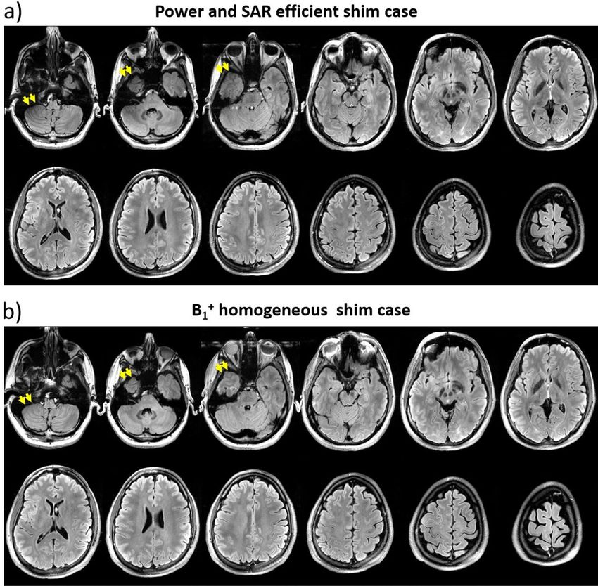
www.nature.com/scientificreports/
Figure 1. The 16-channel Tic Tac Toe (TTT) Tx head coil FDTD model and experimental implementation.
In (a), the coil geometry with the locations of the 16 channels of the transmit head coil, which are divided into
4 levels in Z-direction; In (b), the assembled 16-channel TTT Tx coil and its dimensions; In (c), the region of
interest (white dashed line) plotted over the relative permittivity map of the Duke model at ~ 297.2 MHz (7 T
proton frequency). In (d), the ports, matching rods, and tuning rods of a representative panel of the coil. In
(e), the RF power splitting configuration—exclusively using 2-way and 4-way Wilkinson power dividers—to
drive the 16-channel transmit coil using the system’s sTx or pTx modes. The Tx channels associated with the
coil’s levels 1, 2, 3, and 4 (shown in (a)) experience normalized voltage amplitudes equal to 1, 0.5, 0.5, and 1/√2,
respectively.
(based on electromagnetic simulations) of the TTT design with the transverse electromagnetic (TEM) resonator,
demonstrating an improved transmit field homogeneity and load insensitiveness of the TTT design.
In this work, we describe a methodology for optimizing and operating the TTT transmit coil design for
human imaging studies. Constrained numerical optimizations of the 16-channel TTT transmit coil were per-
formed based on finite-difference time-domain (FDTD) electromagnetic field simulations while considering
the RF power losses in the hardware. Two homogeneous (in terms of B 1+ field) RF shim cases for two different
input power and SAR efficiency levels were experimentally implemented on the single channel (sTx) mode of
a MAGNETOM 7 T MRI system using commercially available RF power splitters and phase shifters (coaxial
cables). In-vivo B1+ maps, as well as T2 SPACE (variable flip angle 3D turbo spin echo) and T2 FLAIR (Fluid
Attenuated Inversion Recovery) sequences were acquired for demonstration purposes. The results demonstrate
homogeneous 7 T neuro imaging. This RF coil system is currently being used in more than 20 patient/disease-
based studies funded by NIH (National Institutes of Health). To date, the current fully implemented version of
the RF coil system has helped acquire more than 1300 neuro in-vivo scans in ongoing 7T human MRI s tudies13,14.
Methods
16‑channel Tic Tac Toe RF coil design. The Tx coil is based on the TTT antennas, previously described
for foot/ankle15, breast16,17, and head imaging at 7T11,12. Briefly, one TTT panel is composed of eight square-
shape transmission lines elements, made using 3D printed polycarbonate and 8 µm-thick copper sheets, con-
nected to each other in a Tic Tac Toe fashion. Four of these elements are connected to excitation ports, and the
other four elements are used for frequency tuning. The antennas are matched and tuned by varying the length
of the copper rods inside the outer struts (Fig. 1d). No capacitors or inductors are necessary for the matching
and tuning of the ports. The Tx coil is composed of four TTT panels positioned around the head, resulting in
a 16-channel transmit coil (Fig. 1a,b). The RF shield is composed of double-sided 4 µm-thick copper sheets
(Polyflon, Germany). Cuts were added on each side of the copper sheet to reduce eddy currents, as described by
Zhao et al.18. For optimal imaging purposes, the RF coil system incorporates an in-house developed 32-channel
receive (Rx)-only insert19.
Scientific Reports | (2021) 11:3370 | https://doi.org/10.1038/s41598-020-79807-9 2
Vol:.(1234567890)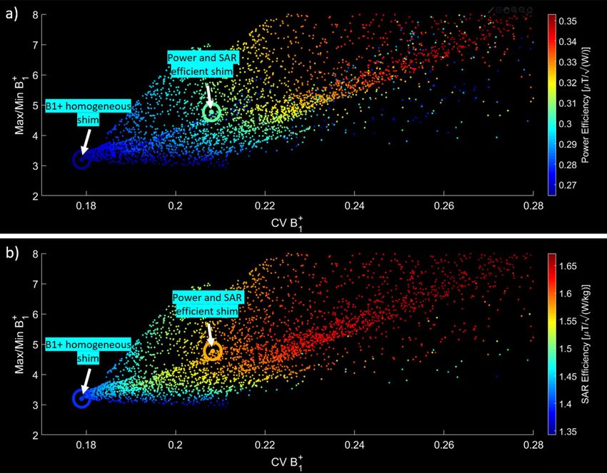
www.nature.com/scientificreports/
FDTD simulations of the Tic Tac Toe coil. The B1+ and electrical fields were simulated using an in-house
developed full-wave FDTD software with an embeded transmission line algorithm for modeling the RF excita-
tion and the c oupling15,17,20–22. The FDTD solver was developed in C language with multi-thread capability23. The
spatial resolution utilized for the combined RF coil and load was 1.59 mm isotropic, and the temporal resolu-
tion was ~ 3 ps (calculated based on FDTD Courant Condition). This represents a rather fine spatial resolution.
For reference, the 10-gm SAR requires averaging more than 2,000 Yee cells. Several works have indicated that
a ~ 5 mm isotropic grid would be sufficient for a reasonable accurate modeling24,25. The simulation time for one
channel to achieve steady state (100,000 time-steps for this model) is about 15 h, allocating 4 cores of an Intel
Xeon Gold 6126 processor and about 4 GB of memory. The coil geometry (Fig. 1a) was created using MATLAB
(MathWorks, USA), totaling 257 × 257 × 276 or ~ 18 million Yee cells. Perfect matching layers were implemented
to absorb the irradiating fields, being 8 layers added on the top of the model (towards the Z direction), 12 on the
sides, and 32 on the bottom26. Each port/channel was excited individually with a differentiated Gaussian pulse,
while all the other ports were terminated with a 50 Ω load using the transmission line numerical model. The
Virtual Family Duke model (version 1.0) was used as the load. The model includes the whole head, neck and the
top of the shoulders, totaling 23 different tissues. The region of interest (ROI) used includes the head regions
from the top of the head through the bottom of the cerebellum and excludes the nasal cavities and ears. The
lower ~ 1 cm of the cerebellum volume is excluded as it contains a minimal number of pixels with brain tissues
in the Duke model. The contour of the ROI mask applied over the permittivity map is shown in Fig. 1c.
The resolution of the FDTD calculated B 1+ fields was then reduced by a factor of 2 to speed up the RF shim-
ming numerical optimizations (described in the next sections), while the resolution of the electric fields was
not changed.
Strategy for RF shimming. Numerical optimizations designed to minimize specific cost functions were
used to manipulate the phases of the RF fields generated by the Tx coil channels. When the optimization goal is
to increase B1+ homogeneity, the coefficient of variation of the B1+ field (CVB+), defined as the standard devia-
1
tion over the mean of the B 1+ inside the ROI, is commonly used as the cost function; however, it may produce
local regions of high or low flip a ngles27. Moreover, even if the CVB+ is in its global minimum, SAR levels could
1
be elevated. To overcome these challenges, the cost functions utilized in this work were combinations of CVB+,
1
maximum B1+ (maxB+), minimum B1+ (minB+), and average SAR. The CVB+ function is continuous and inher-
1 1 1
ently smooth over the multi-dimensional s pace28. As a result, there is a reduced number of local minima pro-
duced by this function, which improves the probability of reaching the global minimum for gradient descend-
ing algorithms. For this reason, we firstly conducted optimizations using the CVB+ as the cost function and
1
using random phases as the initial conditions (the amplitude values were fixed, following the strategy defined
in Fig. 1e). The results from the CVB+ optimizations were then used as the initial conditions for the subsequent
1
optimization, utilizing other cost functions.
The cost functions were minimized using the MATLAB function fmincon including GPU acceleration. The
algorithm used for the CVB+ optimizations was the active-set, due to its high efficiency and high convergence
1
rate from random initial c onditions29. This optimization takes about 10 s per run on a NVIDIA Titan RTX GPU
in a dual Intel Xeon Gold 6230 system. For the optimizations using other cost functions, the interior-point
algorithm was used as it usually performs small steps around the initial conditions instead of larger steps which
could affect the results.
There is an inverse relationship between CVB+ and B1+ efficiency in most multichannel Tx coil designs and a
1
highly homogeneous B 1+ could be achieved at the expense of very low efficiency30. In this scenario, a high input
voltage is required to achieve the desired flip angle, potentially reaching or exceeding the SAR limits and hard-
ware capabilities. To ensure an adequate efficiency for the Tx coil, the optimizations in this work were performed
constraining the mean B+ 1 field to produce 180 degrees flip angle on average with 1 ms square pulse and using
8 kW RF power amplifier. This constraint also considers the measured losses between the RF power amplifier
and the RF coil plug (2.72 dB) as well as the losses associated with the coil struts, shields and ports (1.19 dB),
coil plug (0.30 dB), phase cables (0.53 dB), and power splitters (0.76 dB).
RF shimming for the Tic Tac Toe coil. Step 1: RF power splitting. The TTT RF coil system was designed
to work in either the sTx or parallel-transmit (pTx) modes with the use of Wilkinson power splitters (Fig. 1e).
Based on the eigenmodes of the Tx coil d esign11, the 16-channel Tx coil is composed of 4 excitation levels spa-
tially positioned in the Z direction (Fig. 1a); each level is composed of 4 Tx coil channels. In this work, Level 1
was chosen to be excited with half of the total supplied RF power because of the higher power efficiency associ-
ated with this level and its capacity to produce center bright, as previously demonstrated in reference11. Levels
2 and 3 play an essential role in exciting the lower brain regions, including the cerebellum and the temporal
lobes11. One-eighth of the total supplied RF power was used to excite each of these two levels. Level 4, which pro-
duces a similar B1+ pattern of Level 1 11, received one-quarter of the total supplied RF power. In order to compare
this arrangement with other possible configurations, RF shimming optimizations were performed by randomly
permutating the Tx coil channels amplitudes with the four possible values of amplitudes, as described in Fig. 1e,
and then performing phase-only optimizations using the cost function and steps shown in Fig. 3c.
Step 2: Optimization of the B
1+ field and SAR for a specific RF power splitting configuration. SAR calculation was
incorporated into the optimization software by sampling the electric fields (a voxel was randomly sampled every
Scientific Reports | (2021) 11:3370 | https://doi.org/10.1038/s41598-020-79807-9 3
Vol.:(0123456789)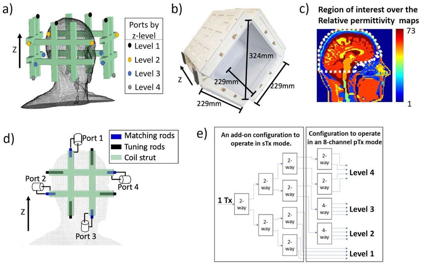
www.nature.com/scientificreports/
Figure 2. S-parameter comparison between simulations and experiments of the Tic Tac Toe 16-channel
Tx head coil. In (a), the FDTD simulated s-matrix using a transmission line model mechanism; in (b), the
experimentally measured s-matrix of the constructed head coil. The color scale limits were modified to
compensate for the electrical losses in the constructed coil (not included in FDTD model).
4 × 4 × 4 voxels) and calculating the average SAR in these samples. This method represents a good estimation
of the global average SAR and was used to speed up the optimizations. It is worth noting that this method was
only applied inside the iterations of the optimization software, the final SAR maps were calculated by averag-
ing the original—high resolution—electric fields (without sampling) for every 10 g of tissue, including partial
volume calculation as described in previous w ork31. The objective function in Eq. (1) was minimized in multiple
optimizations, aiming at achieving a compromise between B 1+ homogeneity and SAR reduction. Each optimiza-
tion—including the post hoc SAR calculation—takes approximately 3 min using the cost function described in
Eq. 1 with a NVIDIA Titan RTX GPU in a dual Intel Xeon Gold 6230 system.
CVB+ MaxB+ /MinB+ SAR
cost = 1
+x× 1 1
+y× (1)
0.17 3 1.5
where CVB+, MaxB+, MinB+ are, respectively, the coefficient of variation, the maximum, and the minimum of the
1 1 1
1 fields inside the region of interest; the constants 0.17, 3, and 1.5 are roughly the expected optimal values of
B+
the CVB+, MaxB+ /MinB+, and SAR, respectively. Dividing the CVB+, MaxB+ /MinB+, and SAR by the expected
1 1 1 1 1 1
values was used to normalize the data and avoid bias, since the resultant value is approximately equal to one for
each term of the cost function; the unit of SAR is W/Kg for an average B+1 of 2μT in the ROI; the values of x and
y randomly variate in every optimization in order to change the weights of MaxB+ /MinB+ and SAR, respectively,
1 1
inside the cost function.
Experimental implementation. Two RF shim cases were experimentally implemented using coaxial
cables as fixed phase shifters and Wilkinson power splitters (Fig. 1e). The imaging experiments - all done on
the sTx mode - were conducted in a whole body 7 T scanner (MAGNETOM, SIEMENS, Germany) with 8 kW
power amplifier capabilities. In-vivo images were acquired in healthy volunteers with informed consent as
part of an approved study by the University of Pittsburgh’s Institutional Review Board (identification number
PRO17030036). All procedures complied with relevant guidelines and regulations for investigational use of the
device in humans.
B 1+ maps were acquired using the Turbo-FLASH s equence 32 with the following parameters: TR/
TE = 2000/1.16 ms; flip angle from 0° to 90° in 18 degrees increments; acquisition time = 12 min, resolu-
tion 3.2 mm isotropic. The output was fitted to a cosine function to produce the flip angle maps. For dem-
onstration purposes, 2D FLAIR and 3D T2-SPACE sequences were used to acquire whole-brain images. The
respective sequences parameters were: (1) 2D FLAIR, TE/TI/TR = 103/2,900/13,500 ms, BW = 230 Hz/pixel,
resolution 0.7 × 0.7 × 2 mm3, acceleration factor 2, 4 interleaved acquisitions (64 transversal slices), total acqui-
sition time = 7:36 min; (2) 3D T2-SPACE sequence (WIP692), TE/TR = 369/3400 ms, BW 488 Hz/pixel, T1/
T2 = 1500/250 ms, acceleration factor 3, with 224 slices in transversal acquisition, acquisition time = 8:11 min,
and bias corrected using the SPM12 package33.
Scientific Reports | (2021) 11:3370 | https://doi.org/10.1038/s41598-020-79807-9 4
Vol:.(1234567890)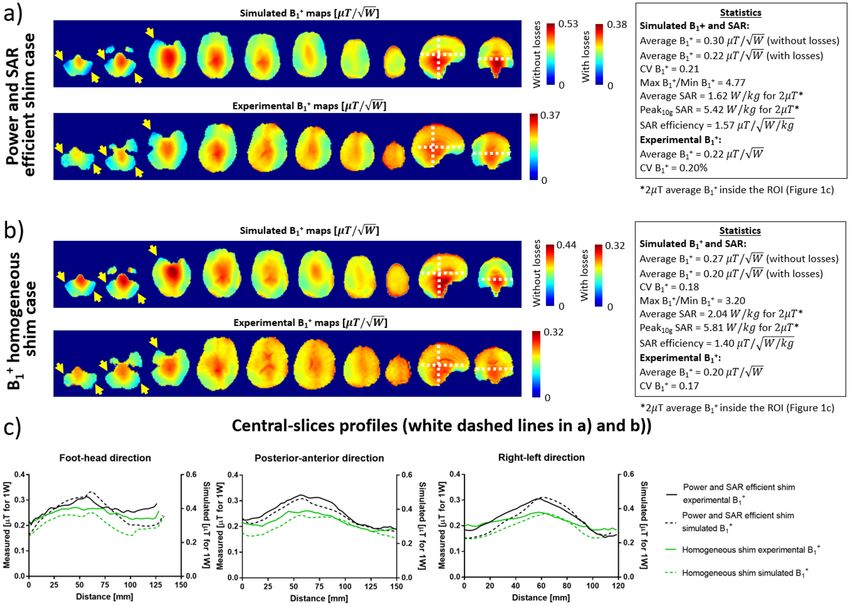
www.nature.com/scientificreports/
Figure 3. Phase-only B1+ RF shim cases for the 16-channel Tic Tac Toe RF coil. This analysis investigates the
performance of several configurations using 2-way and 4-way splitters for implementation on the sTx mode.
In (a, b), the phase-only RF shim cases, with the amplitude scheme derived from the eigenmodes of the RF
coil (described in Fig. 1b) and in reference11, were compared with RF shimming optimizations where the
amplitudes of the Tx channels were randomly permutated but can only take on normalized values = 1, 1/√2, or
0.5. Approximately 300,000 optimizations were performed, presented as the colored dots. The cost functions for
the RF shimming optimizations were the CVB+, CVB+ /minB+ , and max B+ /minB+, following the flowchart in
1 1 1 1 1
(c). The region of interest for the B1+ field stats is the entire head from cerebellum excluding the nasal cavities
and the ears (Fig. 1c). The black arrows point to the case selected as initial condition for the next optimizations,
which was chosen due to having a combination of low CVB+, low max B+ /minB+, and high minB+. The circles
1 1 1 1
represent the RF shim cases with the best CVB+ and the asterisks are the cases with the best max B+ /minB+ for
each cost function.
1 1 1
Results
Figure 2a and b compares the measured and simulated scattering parameters of the 16-channel TTT Tx coil. The
simulated and measured values have Pearson correlation coefficient of 0.935. The measured coupling between
the opposite ports of each TTT panel (highest coupling of the design) was − 4.26 dB on an average while the
simulated value was − 2.68 dB on average. This difference is attributed to electrical losses in the copper, elements,
and ports of the Tx coil, which are not included in the FDTD model. The measured maximum and average
coupling between any pair of panels were − 17.0 dB and − 24.4 dB, respectively.
Figure 3a and b shows the effect of permutating the values of the amplitudes associated with each individual
Tx channel on the overall B 1+ performance. The RF power splitting scheme shown in Fig. 1e is compared with
approximately 300,000 permutations of the amplitude values followed by phase-only RF shimming. The results—
utilizing the RF power splitting scheme from the eigenmodes of the RF coil (Fig. 1e)—demonstrate superior
performance in terms of CVB+, max B+/minB+ , and minB+ . The RF shim case indicated by the black arrow in
1 1 1 1
Fig. 3a and b was chosen as the starting point for the next step in the optimizations, utilizing the cost function
shown in Eq. (1).
Figure 4a and b shows the characteristics of the B 1+ field and SAR variating the weights of the cost func-
tion (Eq. 1) and variating constraints on the average B 1+ intensity. While higher levels of SAR efficiency (i.e.,
lower average SAR) and higher power efficiency can be achieved, it usually comes at the cost of lower levels of
B1+ field homogeneity (higher CVB+ and/or max B+/minB+). From the scattering plots, we chose two cases for
1 1 1
experimental implementation (arrows in Fig. 4a,b): “B1+ homogeneous shim” situated in the edge of the graph,
representing the maximum homogeneity in the lower limit of power efficiency, and “Power and SAR efficiency
Scientific Reports | (2021) 11:3370 | https://doi.org/10.1038/s41598-020-79807-9 5
Vol.:(0123456789)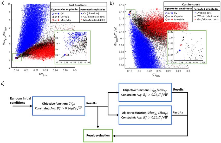
www.nature.com/scientificreports/
Figure 4. SAR and B1+ phase-only RF shimming of the 16-channel Tic Tac Toe RF coil. The B1+ homogeneity
parameters (CVB+ and max B+ /minB+ in X and Y axes of the plot, respectively) are compared with the power
1 1 1
efficiency (a) and SAR efficiency (b). Each point corresponds to an RF shim case using a cost function (Eq. 1)
that includes CVB+, max B+ /minB+, and average SAR. Average B 1+ constraints were also included. Two RF
1 1 1
1+
shim cases were chosen for experimental implementation: (1) power and SAR efficient shim and (2) B
homogeneous shim.
shim” which is situated in the middle of the graph and represents a compromise between B 1+ homogeneity, B
1+
efficiency, and SAR efficiency.
Fig. 5a–c shows a comparison of the two experimentally implemented, non-subject-specific RF shim cases.
Specifically, the comparison shows the experimental B1+ field maps and the corresponding simulated results on
the Duke model. In Fig. 5a, a power and SAR efficient √
RF shim case is shown. It achieves a SAR efficiency of
1.57 µT/ W/kg (simulated), average B 1+ of 0.22 µT/ W (experimental), CVB+ of 20% (experimental), and
1
max B+/minB+ of 4.77 (simulated). The B 1+ homogeneous RF shim case (Fig. 5b) has a SAR efficiency of 1.40
1 1
√
µT/ W/kg (simulated), average B 1+ of 0.20 µT/ W (experimental), CVB+ of 17% (experimental), and max B+
1 1
/minB+ of 3.20 (simulated). Figure 5c shows the profiles in the central slices of the experimental and simulated
1
1+ field for the two RF shim cases. The impact of having lower B1+ field intensities can be seen near the yellow
B
arrows displayed over the B1+ field maps in Fig. 5a and b. Figure 6 shows the effects of the RF shimming on the
FLAIR images, acquired on the same volunteer.
Figure 7 shows representative slices of the T2-weighted 3D SPACE images acquired in a volunteer with large
head size (approximately 205 mm in anterior–posterior direction from the forehead) using the B 1+ homogeneous
+
RF shim case shown in Fig. 5b. Using an MR sequence that requires high levels of B1 homogeneity, the images
show that the implemented RF shim case provides non-subject specific homogeneous field distribution and it
achieves full brain coverage – including the cerebellum and temporal lobes – in a relatively larger head.
Scientific Reports | (2021) 11:3370 | https://doi.org/10.1038/s41598-020-79807-9 6
Vol:.(1234567890)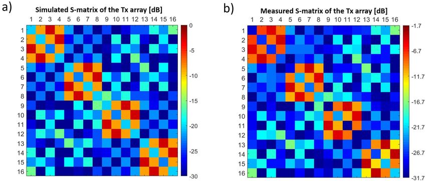
www.nature.com/scientificreports/
Figure 5. Simulated and experimental B1+ maps comparisons for 2 RF shim cases. In (a), simulated and in-vivo
B1+ maps and statistics of the power and SAR efficient RF shim case. In (b), simulated and in-vivo B1+ maps
for the B1+ homogeneous RF shim case. The statistics from the simulations were calculated over the region
of interest shown in Fig. 1c. The yellow arrows point to regions of low B1+ that were mitigated with the B1+
homogeneous RF shim case. In (c), the central slice profiles from the simulated and experimental B 1+ maps
[white dashed lines in (a) and (b)]. The differences observed in the mean B1+ are due to the electrical losses in
the coil structure/cables/plugs/ports/connections/splitters. With a linear system and superposition principle,
the overall loss is included as part of the simulation data (“With losses” colorbar). Since the overall electrical
loss does not affect B 1+ distribution (represents a fixed drop in the intensity), the calculated CV values for
the simulations and experiments are comparable for the two RF shim cases (20% vs. 21% and 17% vs. 18%).
After including the overall measured electrical loss (27.4% in voltage as described in “Methods” section), the
maximum √and average values for the simulations and experiments are also comparable,
√ 0.38 vs. 0.37 and 0.32 vs.
0.32 µT/ W for maximum B 1+ field, and 0.22 vs. 0.22 and 0.20 vs. 0.20 µT/ W for the average B1+ field.
Discussions
In this work, a 16-channel transmit coil based on the Tic Tac Toe design was optimized using non-subject spe-
cific phase-only RF shimming. The RF shimming approach combined with the coil’s 4 excitation levels in the Z
direction can significantly impact the Tx coil performance by introducing tradeoffs among RF power efficiency,
B1+ field homogeneity, and SAR. These parameters can be controlled, depending on the imaging application and
the RF amplifier capacity, by changing the lengths of the coaxial cables feeding the coil or by using pTx systems.
S‑matrix comparison. The RF TTT transmit coil was simulated with a transmission line algorithm for
modeling the excitation and coupling as part of the in-house developed FDTD p ackage23. Accurate electro-
magnetic modeling of the coil’s coupling is critical for implementing RF shimming fully based on B 1+ and elec-
tric fields calculated from electromagnetic simulations. The simulated and measured s-matrices are comparable
(Fig. 2a,b, respectively), with a Pearson correlation coefficient of 0.935. There is an offset in the values (− 1.7 dB
on average) that is related to the losses in the coil and connectors. We did not include the losses in the simula-
tions since we believe there is still a margin for improvement. For example, using less-porous CNC-machined
Teflon parts instead of 3D printed polycarbonate may reduce the losses in the coil.
Strategy for power splitting among the channels. Previous work11 has showed that the 16-channel
RF coil contains different levels of power efficiencies in accordance with the position of the ports in Z direction
Scientific Reports | (2021) 11:3370 | https://doi.org/10.1038/s41598-020-79807-9 7
Vol.:(0123456789)www.nature.com/scientificreports/
Figure 6. Axial slices of the FLAIR images acquired at resolution of 0.7 × 0.7 × 2 mm3. The images show
the differences between the power and SAR efficient (a) and B1+ homogeneous (b) shim cases. The yellow
arrows point to the regions where the dropout was mitigated by the B1+ homogeneous case. The parameters
of the acquisition were: TE/TI/TR = 103/2900/13,500 ms, acceleration factor 2, BW = 230 Hz/Px, transversal
acquisition of 64 slices, field of view 224 × 176.4 mm2 in axial plane, and acquisition time = 7:36 min.
(direction of the static magnetic field). The voltage amplitudes for the Tx channels were chosen so that the most
efficient coil levels are excited with a larger fraction of the supplied RF power. This approach produces improved
B1+ homogeneity (Fig. 3a) and high minimum B 1+ intensity inside the ROI (Fig. 3b) when compared with other
possible combinations using the same RF power splitter configuration. All cases presented can be easily imple-
mented using 2-way and 4-way RF power splitters and coaxial cables as phase shifters on the system’s sTx or pTx
modes.
B1+ and SAR RF shimming. Figure 4a and b shows the flexibility of the phase-only RF shimming scheme
in combination with the 16-channel TTT coil design, demonstrating the tradeoff among SAR efficiency, B1+
efficiency, and B1+ homogeneity. Based on the electromagnetic simulations, a homogeneity of 18% (CVB+) can
1
be achieved within the ROI, resulting in a SAR efficiency of 1.40 µT/ W/kg and an average B1+ of 0.27 µT.
+
Increasing the weight of the SAR
in the cost function (Eq. 1) and increasing the mean B1 constraint improved
the SAR efficiency to 1.57 µT/ W/kg while maintaining a CVB+ of 21% and an average B 1+ field of 0.30 µT.
1
These values of SAR efficiency and B1+ field homogeneity represent an improved performance for 7 T RF head
Scientific Reports | (2021) 11:3370 | https://doi.org/10.1038/s41598-020-79807-9 8
Vol:.(1234567890)www.nature.com/scientificreports/
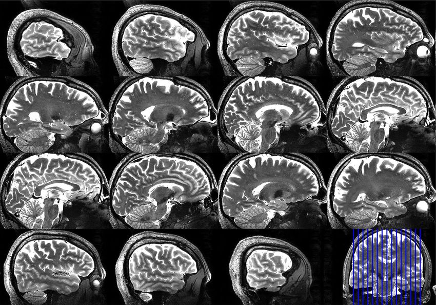
Figure 7. Sagittal slices of the 3D-SPACE acquired at 0.6 mm isotropic resolution, showing full brain and
cerebellum coverage in a volunteer with large head size (~ 205 mm in anterior–posterior direction measured
from the forehead). The images were obtained using the B 1+ homogeneous RF shim case on the sTx mode. The
parameters of the acquisition were: TE/TR = 369/3400 ms, acceleration factor 3, BW = 488 Hz/Px, transversal
acquisition of 224 slices, field of view 192 × 165.6 mm2 in axial plane, and acquisition time = 8:11 min.
coils when compared with traditional RF coils. As a comparison, Krishnamurthy et al.12 reported the values of
SAR efficiency of 1.27 µT/ W/kg and homogeneity of 27% for the TEM resonator, using the same simula-
tion environment utilized in this work. Other studies investigated the SAR performance for several other coil
designs34–37, however the simulations were performed in different software environments and often using differ-
ent head models, which makes the comparison with this work challenging.
In general, the cost function combining CVB+, max B+/minB+, and SAR with the average B+ 1 constraint pre-
1 1 1
sented a good performance for this particular RF coil design, as it allowed different operational points where it is
possible to minimize CVB+, max B+/minB+, or maximize SAR efficiency (Fig. 4a,b), depending on the application.
1 1 1
It is important to note that the optimal cost function may vary depending on the RF coil design, the constraints
included in the simulation, and the ROI used.
Experimental verification. Figure 5a and b shows the experimental implementation of the two RF shim
cases and the corresponding simulated B1+ maps. The first case is intended for higher SAR and RF power effi-
ciency; the second case is optimized for higher B1+ homogeneity. The images—using a high flip angle sequence
(FLAIR)—shown in Fig. 6 demonstrate the differences between the two RF shim cases in the cerebellum and
temporal lobe, which are very challenging regions at 7 T MRI38,39. Although the B1+ homogeneous RF shim case
presents lower RF power efficiency, the improved B1+ homogeneity justify its use, since the lower RF power
efficiency can be compensated by adjusting the input voltage amplitude or by increasing the pulse width of the
sequences.
Figure 5c shows a comparison between the simulated and experimental B1+ profiles. The differences in the
intensity can be explained by the losses in the splitters/cables/connectors (approximately 17% measured loss in
voltage) and losses in the coil. The differences in the field distribution can be attributed to the model approxima-
tions and differences between the head model size/position and the in-vivo. For instance, the brain in the model
used is about 14 cm long in foot-head direction, while the volunteer is about 12.5 cm.
The 3D T2-SPACE whole-brain and cerebellum images, shown in Fig. 7, were acquired at 7 T using the B 1+
homogeneous RF shim case implemented on the sTx mode (Fig. 5b). The results demonstrate that homogeneous
Scientific Reports | (2021) 11:3370 | https://doi.org/10.1038/s41598-020-79807-9 9
Vol.:(0123456789)www.nature.com/scientificreports/
whole-brain imaging in a volunteer with a large head size is achievable with a challenging T2-weighted sequence
at 7 T M RI40–42—often associated with significantly lower signal in the temporal lobe and cerebellum.
The RF coil design presented in this work has lower power efficiency, but better SAR efficiency, when com-
pared to more traditional 7 T RF head coil designs. The lower power efficiency is attributed to the strong coupling
between opposite elements of the TTT coil, which causes a significant portion of the transmitted power to be
dissipated in the RF power splitters and the scanner system’s√circulator. For instance, the two RF shim cases
presented in this work have a mean B 1+ of 0.27 and 0.30 µT/ W in the simulations (not considering losses in
the hardware). Using the same software environment, Krishnamurthy et al.12 demonstrated that the 4-channel,
16-element√ TEM resonator (with the same length as the 16-channel TTT coil) presents a power efficiency of
0.45 µT/ W . However, considering all the power losses in the system and in the coil, the 16-channel TTT coil
still provides enough mean B 1+ intensity to have inversion using 1 ms square pulse with 8 kW power amplifier
(standard in older 7 T scanners), which is sufficient for most imaging applications. The B1+ homogeneous RF
shim case (Fig. 5b) is currently being heavily used with the sTx mode on more than 20 NIH patient/disease
studies conducted in our facility13,14 due to its high B1+ homogeneity and extended coverage in challenging-to-
image regions in the head at 7 T.
Data availability
The data that support the findings of this study are available from the corresponding author upon request.
Received: 29 June 2020; Accepted: 26 November 2020
References
1. Moser, E., Stahlberg, F., Ladd, M. E. & Trattnig, S. 7-T MR–from research to clinical applications?. NMR Biomed. 25, 695–716.
https://doi.org/10.1002/nbm.1794 (2012).
2. Fiedler, T. M., Ladd, M. E. & Bitz, A. K. SAR simulations & safety. Neuroimage 168, 33–58. https://doi.org/10.1016/j.neuroimage
.2017.03.035 (2018).
3. Staewen, R. S. et al. 3-D FLASH imaging using a single surface coil and a new adiabatic pulse, BIR-4. Invest. Radiol. 25, 559–567
(1990).
4. Tannús, A. & Garwood, M. Adiabatic pulses. NMR Biomed. 10, 423–434 (1997).
5. Zhu, Y. Parallel excitation with an array of transmit coils. Magn. Reson. Med. 51, 775–784. https://doi.org/10.1002/mrm.20011
(2004).
6. Zhang, Z. et al. Reduction of transmitter B1 inhomogeneity with transmit SENSE slice-select pulses. Magn. Reson. Med. 57,
842–847. https://doi.org/10.1002/mrm.21221 (2007).
7. Wu, X. et al. Simultaneous multislice multiband parallel radiofrequency excitation with independent slice-specific transmit B1
homogenization. Magn. Reson. Med. 70, 630–638. https://doi.org/10.1002/mrm.24828 (2013).
8. Orzada, S. et al. Time-interleaved acquisition of modes: An analysis of SAR and image contrast implications. Magn. Reson. Med.
67, 1033–1041. https://doi.org/10.1002/mrm.23081 (2012).
9. Orzada, S. et al. RF excitation using time interleaved acquisition of modes (TIAMO) to address B1 inhomogeneity in high-field
MRI. Magn. Reson. Med. 64, 327–333. https://doi.org/10.1002/mrm.22527 (2010).
10. Ibrahim, T. S. et al. Effect of RF coil excitation on field inhomogeneity at ultra high fields: A field optimized TEM resonator. Magn.
Reson. Imaging 19, 1339–1347 (2001).
11. Santini, T. et al. In-vivo and numerical analysis of the eigenmodes produced by a multi-level Tic-Tac-Toe head transmit array for
7 Tesla MRI. PLoS ONE 13, e0206127. https://doi.org/10.1371/journal.pone.0206127 (2018).
12. Krishnamurthy, N. et al. Computational and experimental evaluation of the Tic-Tac-Toe RF coil for 7 Tesla MRI. PLoS ONE 14,
e0209663. https://doi.org/10.1371/journal.pone.0209663 (2019).
13. Smagula, S. F. et al. Association of hippocampal substructure resting-state functional connectivity with memory performance in
older adults. Am. J. Geriat. Psychiatry https://doi.org/10.1016/j.jagp.2018.03.003 (2018).
14. Farhat, N. S., Theiss, R., Santini, T., Ibrahim, T. S. & Aizenstein, H. J. Neuroimaging of Small Vessel Disease in Late-Life Depres-
sion. In Frontiers in Psychiatry 95–115 (Springer, New York, 2019).
15. Santini, T. et al. A new RF transmit coil for foot and ankle imaging at 7T MRI. Magn. Reson. Imaging 45, 1–6. https://doi.
org/10.1016/j.mri.2017.09.005 (2018).
16. Kim, J. et al. Development of a 7 T RF coil system for breast imaging. NMR Biomed. https://doi.org/10.1002/nbm.3664 (2016).
17. Kim, J. et al. Experimental and numerical analysis of B1+ field and SAR with a new transmit array design for 7T breast MRI. J.
Magn. Reson. 269, 55–64. https://doi.org/10.1016/j.jmr.2016.04.012 (2016).
18. Zhao, Y. et al. Dual optimization method of radiofrequency and quasistatic field simulations for reduction of eddy currents gener-
ated on 7T radiofrequency coil shielding. Magn. Reson. Med. https://doi.org/10.1002/mrm.25424 (2014).
19. Ibrahim, T. et al. 20-To-8 Channel Tx Array with 32-Channel Adjustable Receive-Only Insert for 7T Head Imaging. (International
Society of Magnetic Resonance in Medicine, Salt Lake City, Utah, 2013).
20. Raval, S. B. et al. Ultra-high field upper extremity peripheral nerve and non-contrast enhanced vascular imaging. PLoS ONE 12,
e0175629. https://doi.org/10.1371/journal.pone.0175629 (2017).
21. Raval, S. B. et al. Ultra-high-field RF coil development for evaluating upper extremity imaging applications. NMR Biomed. https
://doi.org/10.1002/nbm.3582 (2016).
22. Ibrahim, T. S., Mitchell, C., Abraham, R. & Schmalbrock, P. In-depth study of the electromagnetics of ultrahigh-field MRI. NMR
Biomed. 20, 58–68 (2007).
23. Ibrahim, T. S., Hue, Y. K. & Tang, L. Understanding and manipulating the RF fields at high field MRI. NMR Biomed. 22, 927–936.
https://doi.org/10.1002/nbm.1406 (2009).
24. Eichfelder, G. & Gebhardt, M. Local specific absorption rate control for parallel transmission by virtual observation points. Magn.
Reson. Med. 66, 1468–1476. https://doi.org/10.1002/mrm.22927 (2011).
25. Collins, C. M. & Smith, M. B. Spatial resolution of numerical models of man and calculated specific absorption rate using the
FDTD method: A study at 64 MHz in a magnetic resonance imaging coil. J. Magn. Reson. Imaging 18, 383–388 (2003).
26. Ibrahim, T. S. & Lee, R. Evaluation of MRI RF probes utilizing infrared sensors. IEEE Trans. Biomed. Eng. 53, 963–967. https://
doi.org/10.1109/TBME.2006.871892 (2006).
27. Ferrand, G. et al. Generalized double-acquisition imaging for radiofrequency inhomogeneity mitigation in high-field MRI: Experi-
mental proof and performance analysis. Magn. Reson. Med. 67, 175–182. https://doi.org/10.1002/mrm.23006 (2012).
Scientific Reports | (2021) 11:3370 | https://doi.org/10.1038/s41598-020-79807-9 10
Vol:.(1234567890)www.nature.com/scientificreports/
28. Nehrke, K., Sprinkart, A. M. & Bornert, P. An in vivo comparison of the DREAM sequence with current RF shim technology.
Magma 28, 185–194. https://doi.org/10.1007/s10334-014-0454-3 (2015).
29. Hoyos-Idrobo, A., Weiss, P., Massire, A., Amadon, A. & Boulant, N. On variant strategies to solve the magnitude least squares
optimization problem in parallel transmission pulse design and under strict SAR and power constraints. IEEE Trans. Med. Imaging
33, 739–748. https://doi.org/10.1109/TMI.2013.2295465 (2014).
30. Tang, L., Hue, Y. K. & Ibrahim, T. S. Studies of RF shimming techniques with minimization of RF power deposition and their
associated temperature changes. Concepts Magn. Reson. B 39, 11–25 (2011).
31. Caputa, K., Okoniewski, M. & Stuchly, M. A. An algorithm for computations of the power deposition in human tissue. IEEE
Antennas Propag. Mag. 41, 102–107 (1999).
32. Klose, U. J. M. Mapping of the radio frequency magnetic field with a MR snapshot FLASH technique. Neuroimage 19, 1099–1104
(1992).
33. Ashburner, J. & Friston, K. J. Unified segmentation. Neuroimage 26, 839–851 (2005).
34. Kozlov, M. & Turner, R. Analysis of RF transmit performance for a 7T dual row multichannel MRI loop array. Conf. Proc. 547–553,
2011. https://doi.org/10.1109/IEMBS.2011.6090101 (2011).
35. Kozlov, M. & Möller, H. E. Safety excitation efficiency of MRI 300MHz dualrow transmit arrays. IEEE Antennas and Propagation
& USNC/URSI National Radio Science Meeting (2015).
36. Collins, C. M., Li, S. & Smith, M. B. SAR and B1 field distributions in a heterogeneous human head model within a birdcage coil.
Magn. Reson. Med. 40, 847–856. https://doi.org/10.1002/mrm.1910400610 (1998).
37. Mao, W., Wang, Z., Smith, M. B. & Collins, C. M. Calculation of SAR for transmit coil arrays. Concepts Magn. Reson. 31B, 127–131.
https://doi.org/10.1002/cmr.b.20085 (2007).
38. Clement, J. D., Gruetter, R. & Ipek, O. A human cerebral and cerebellar 8-channel transceive RF dipole coil array at 7T. Magn.
Reson. Med. https://doi.org/10.1002/mrm.27476 (2018).
39. Zwanenburg, J. J., Hendrikse, J., Visser, F., Takahara, T. & Luijten, P. R. Fluid attenuated inversion recovery (FLAIR) MRI at 7.0
Tesla: comparison with 1.5 and 3.0 Tesla. Eur. Radiol. 20, 915–922 (2010).
40. Massire, A. et al. Parallel-transmission-enabled three-dimensional T2 -weighted imaging of the human brain at 7 Tesla. Magn.
Reson. Med. 73, 2195–2203. https://doi.org/10.1002/mrm.25353 (2015).
41. Gizewski, E. et al. High-resolution anatomy of the human brain stem using 7-T MRI: Improved detection of inner structures and
nerves?. Magn. Reson. Med. 56, 177–186. https://doi.org/10.1007/s00234-013-1312-0 (2014).
42. Eggenschwiler, F. et al. 3D T2-weighted imaging at 7T using dynamic kT-points on single-transmit MRI systems. Magn. Reson.
Med. 29, 347–358. https://doi.org/10.1007/s10334-016-0545-4 (2016).
Acknowledgements
This work was supported by NIH R01MH111265, R01AG063525, and R01EB009848. The author Tales Santini
was partially supported by the CAPES Foundation, Ministry of Education of Brazil, 13385/13-5. This research
was also supported in part by the University of Pittsburgh Center for Research Computing (CRC) through the
resources provided.
Author contributions
Conceptualization: T.S., H.J.A., T.S.I.; Simulation of the coil design: N.K., T.S.; Implementation of the optimiza-
tion methods: TS, SW; MRI image acquisition: T.S., T.M., T.S.I.; Initial manuscript draft: T.S., T.S.I.; Manuscript
revision: all authors.
Competing interests
The authors declare no competing interests.
Additional information
Correspondence and requests for materials should be addressed to T.S.I.
Reprints and permissions information is available at www.nature.com/reprints.
Publisher’s note Springer Nature remains neutral with regard to jurisdictional claims in published maps and
institutional affiliations.
Open Access This article is licensed under a Creative Commons Attribution 4.0 International
License, which permits use, sharing, adaptation, distribution and reproduction in any medium or
format, as long as you give appropriate credit to the original author(s) and the source, provide a link to the
Creative Commons licence, and indicate if changes were made. The images or other third party material in this
article are included in the article’s Creative Commons licence, unless indicated otherwise in a credit line to the
material. If material is not included in the article’s Creative Commons licence and your intended use is not
permitted by statutory regulation or exceeds the permitted use, you will need to obtain permission directly from
the copyright holder. To view a copy of this licence, visit http://creativecommons.org/licenses/by/4.0/.
© The Author(s) 2021
Scientific Reports | (2021) 11:3370 | https://doi.org/10.1038/s41598-020-79807-9 11
Vol.:(0123456789)You can also read