Tools for pressure core sub-coring and pore-scale micro-CT (computed tomography) scans - Scientific Drilling
←
→
Page content transcription
If your browser does not render page correctly, please read the page content below
Technical Developments
Sci. Dril., 29, 59–67, 2021
https://doi.org/10.5194/sd-29-59-2021
© Author(s) 2021. This work is distributed under
the Creative Commons Attribution 4.0 License.

              Tools for pressure core sub-coring and pore-scale
                  micro-CT (computed tomography) scans
            Yongkoo Seol1 , Liang Lei1,a , Karl Jarvis1,2 , Daniel Hill1,3 , Jeong-Hoon Choi1,2 , Taehyung Park1 ,
                            Xuerui Gai1 , Greg Wunderlich4 , Bill Grey4 , and Chris McArdle4
       1 National   Energy Technology Laboratory, U.S. Department of Energy, Morgantown, West Virginia 26507, USA
                            2 Leidos Research Support Team, Morgantown, West Virginia 26507, USA
                                      3 AMENTUN, Morgantown, West Virginia 26507, USA
                                    4 AMENTUM, Greenwood Village, Colorado 80111, USA
                    a now at: School of Engineering, Westlake University, Hangzhou, Zhejiang 310024, China

                                   Correspondence: Liang Lei (leiliang@westlake.edu.cn)

            Received: 15 August 2020 – Revised: 11 January 2021 – Accepted: 13 January 2021 – Published: 26 April 2021

       Abstract. The pore habits of gas hydrate in natural sediment matrices provide essential clues for understanding
       physical (mechanical, thermal, hydraulic, and electrical) properties of hydrate-bearing sediments, yet there are
       no tools that can directly visualize the pore habits of natural gas hydrate other than indirect interpretation based
       on core-scale or field-scale observations. A significant challenge is to obtain a mini-core from pressure cores
       retrieved from natural reservoirs for high-resolution micro-CT (computed tomography) scans while maintaining
       pressure and temperature conditions required for stability of gas hydrate during all operational steps including
       manipulation, cutting, transferring, sub-coring and CT scanning. We present a new set of tools for pore-scale
       micro-CT imaging of natural hydrate-bearing sediments while maintaining pressure and temperature control.
       The tests with laboratory-prepared cores and pressure cores successfully demonstrate the capability of this set of
       tools to subsample a mini-core from pressure cores, transfer the mini-core to an X-ray transparent core holder,
       and conduct micro-CT scans. Successfully obtained CT images prove the functionality of this set of tools.

1   Introduction                                                   cal properties such as permeability and mechanical strength
                                                                   are directly affected by the sediment fabric. Maintaining the
                                                                   original sediment fabric, therefore, is of critical importance
Physical properties of deep marine gas hydrate-bearing sed-        for the characterization of these sediments. Additionally, the
iments draw growing attention as they are a critical input         study of hydrate-bearing sediments requires the preservation
for predicting energy extraction efficiency, seafloor settle-      of hydrate and its pore habits in natural environments, which
ment and wellbore stability. Due to high pressure in typi-         is of special interest because gas hydrate as a solid is a part
cal energy-enriched environments, gas bubbles as well as the       of the sediment skeleton that affects both the mechanical
dissolved gas in the fluid can expand drastically when de-         and hydrological behaviors of the sediments (Boswell, 2009;
pressurized. Gas hydrate in solid crystalline form can release     Boswell and Collett, 2011).
gas with ∼ 164 times the hydrate volume under standard con-           A pressure-coring technique, which preserves the fluid
ditions (Boswell and Collett, 2011). High pressure and low         pressure of the sample during the coring process (Amann et
temperature are required to maintain the stability of gas hy-      al., 1997; Dickens et al., 2003; Kvenvolden et al., 1983; Pet-
drate (Makogon, 1997; Sloan and Koh, 2007). If the fluid           tigrew, 1992; Qin et al., 2005; Dai et al., 2012; Schultheiss
pressure is not maintained during the coring process, the gas      et al., 2009), is maturing rapidly with gas hydrate explo-
contained in the sediment pores, in the form of free gas, dis-     ration activities in Japan, South Korea, India, China, and re-
solved gas or solid gas hydrate, could expand drastically and      cently the US (Collett et al., 2019; Flemings et al., 2018; Ya-
potentially destroy the initial fabric of the sediments. Physi-

Published by Copernicus Publications on behalf of the IODP and the ICDP.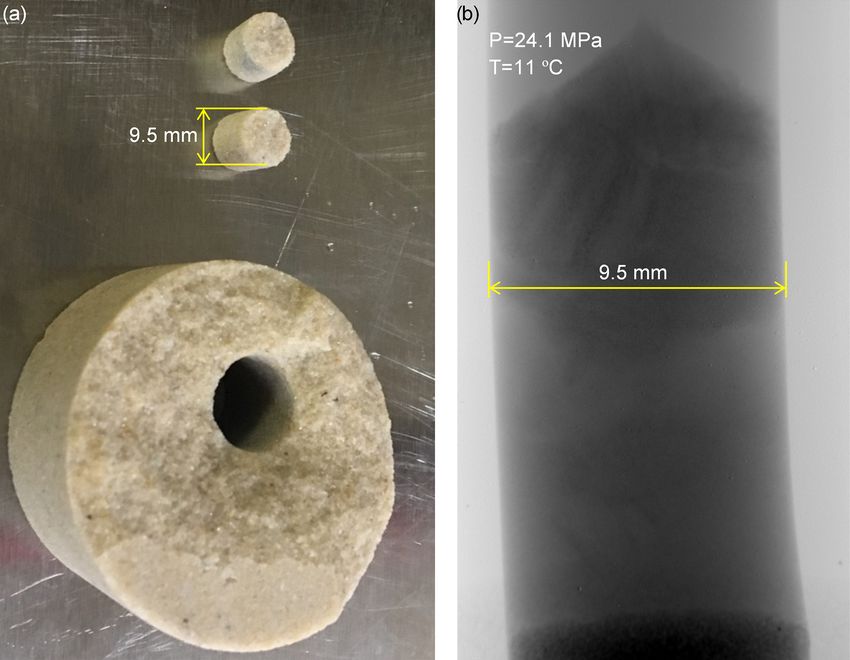
60 Y. Seol et al.: Tools for pressure core sub-coring and pore-scale micro-CT scans
mamoto, 2015; Yun et al., 2011; Zhang et al., 2014). The core together with its hosting micro-CT scanning assembly is
physical properties of pressure cores have been measured then covered in thermal insulation and relocated to the micro-
at core scale with specially developed tools (Fang et al., CT scanner for 3D pore-scale scanning. Figure 1 shows the
2020; Priest et al., 2019; Santamarina et al., 2015; Yoneda key components that enable this capability: (a, b) the manipu-
et al., 2018; Yoneda et al., 2019; Yun et al., 2011), cover- lator and cutter used for general pressure core manipulation,
ing mechanical, thermal, hydraulic and electric properties. temporary storage and cutting; (c, d) the sub-coring tool to
Interpretations of the results are largely based on idealized drill a mini-core; and (e, f) the sub-coring chamber where the
pore habits: grain coating, cementing and pore filling (Dai et mini-core drilling occurs and the attached micro-CT scan-
al., 2012; Waite et al., 2009; Yun et al., 2007). Defining the ning assembly to receive and scan the mini-core with X-ray
real distribution and morphology of hydrate within the sedi- CT. The functions of each component will be described in
ment matrix is critical for understanding the sediment phys- the following sections.
ical properties and resulting interpretations. However, there
are no tools that allow for direct visualization of pore-scale 2.1 General operations for pressure cores
behaviors of natural hydrate-bearing sediments to date.
A micro-CT (computed tomography) technique utilizing The pressure core is retrieved from the Gulf of Mexico dur-
phase contrast has been developed to obtain the pore-scale ing the University of Texas (UT) Hydrate Pressure Coring
structure of laboratory-synthesized methane hydrate-bearing Expedition 1 (UT-GOM2-1), at the well in Green Canyon
sediments (Lei et al., 2018), but the core size must be less Block 955 (GC 955). The core is from the hydrate reservoir
than 10 mm in order to achieve high-resolution scans. The di- between 425 and 428 m below the sea floor, and the reservoir
ameter of whole-round pressure core samples from currently is composed of fine sands interbedded with clays according
available pressure core drilling tools is > 50 mm (Schultheiss to the LWD log characterization (Fang et al., 2020; Boswell
et al., 2009). Therefore, a toolset is essential to enable the re- et al., 2012).
trieval of a mini-core from a larger pressure core while main- Pressure cores are initially held under pressure in specially
taining the pressure and temperature of the hydrate-bearing designed transport chambers. A series of operations are re-
sediments under in situ conditions during the whole process. quired to manipulate and cut the pressure core into proper
Sub-coring tools have been developed for this specific pur- lengths before they get transferred into various function mod-
pose (Jin et al., 2014; Schultheiss et al., 2009; Parkes et al., ules, such as a cutter or a CT scanning chamber, for special-
2009), but they have not been applied to pressure cores for ized characterization. There is literature available (Santama-
pore-scale micro-CT scanning. rina et al., 2012; Schultheiss et al., 2009) describing the gen-
This work presents a set of tools that can subsample a eral concept of pressure core manipulation. Figure 2 shows
mini-core from pressure cores and transfer it into an X-ray the cross-section view of a typical pressure core transfer pro-
transparent core holder under in situ conditions. The mini- cess: (a) pressurize the temporary storage chamber and the
core is then scanned with a micro-CT scanner with a resolu- space between two ball valves with deionized water to the
tion of 2 µm. Mini-core sub-coring and transferring processes same pressure as that in the transportation chamber; (b) open
are presented together with basic operations on full-size pres- the two ball valves and use the grabber to grab the core sleeve
sure cores including grabbing, manipulation, and cutting. in the function module (transportation chamber as an exam-
Details on CT scan configuration and the X-ray transpar- ple here); note that the friction between the pressure core and
ent core holder are covered in Lei et al. (2018) and Seol et the sleeve binds them together; (c) transfer the pressure core
al. (2019). to the temporary storage chamber by retrieving the grabber
and close the left ball valve. The key component of pressure
core handling is the manipulator module (Fig. 1a and b). It
2 Concept of design and operation procedure consists of a manipulator that pushes or pulls pressure cores
inside core sleeves with a sleeve grabber, a temporary storage
This section describes the concept design and operational se- chamber, and a ball valve (components A, B and C in Fig. 2).
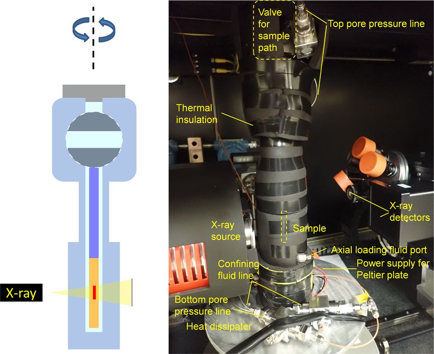
quence to achieve the desired functionality. The requirement Two viewports are installed on the temporary storage cham-
is to drill a mini-core (9.5 mm in diameter) out of the original ber to visually check the position and quality of the pressure
pressure core (50 mm in diameter) and transfer the mini-core core. The pressure core is retrieved from a function module
into the attached micro-CT scanning assembly. Temperature with the procedure displayed in Fig. 2. A similar approach is
is maintained inside an environmental chamber at 6 ± 0.5 ◦ C used to insert the pressure core into other function modules.
where drilling and transfer of the mini-core occur. The fluid Note that the function module could be a cutter (Fig. 1a),
pressure is maintained by ISCO high-pressure syringe pumps storage chamber, sub-coring chamber (Fig. 1e and f), or any
at 24.1 MPa (3500 psi). The pressure rating of this system is other stand-alone modules built for specific purposes.
34.5 MPa (5000 psi). Due to the pressures required for such
a process, this set of tools is designed to ASME B31.3 and
ASME BVPC Section VIII, Div 1, where required. The mini-
Sci. Dril., 29, 59–67, 2021 https://doi.org/10.5194/sd-29-59-2021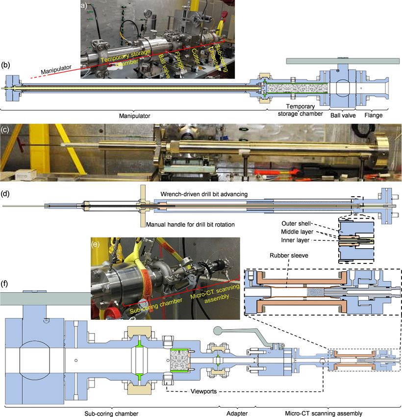
Y. Seol et al.: Tools for pressure core sub-coring and pore-scale micro-CT scans                                                         61

Figure 1. Pressure core Characterization and X-ray visualization Tool (PCXT) components. (a) Manipulator module and automated cutter,
(b) section view of the manipulator module, (c) sub-coring tool, (d) section view of the sub-coring tool, (e) sub-coring chamber and micro-
CT scanning assembly that includes a small ball valve, core holder adapter and beryllium core holder, and (f) section view of the sub-coring
chamber and micro-CT scanning assembly.

2.2   Pre-operations before sub-coring                                  the CT scan chamber into the manipulator. Then the pressure
                                                                        core is pushed into the automated cutter, placed at a prede-
Core-scale CT scans that provide the overview of the whole
                                                                        termined location, cut into appropriate lengths, and pushed
core could help verify the status and quality of the pressure
                                                                        further into the position for the sub-coring process (Fig. 3).
core before any further operation, since the pressure core de-
                                                                        The residual pressure core is pulled back to the temporary
grades during transportation and long-term storage, due to
                                                                        storage chamber for other purposes.
the lack of effective stress-caused core expansion and hy-
drate dissolution into surrounding water (Dai and Santama-
rina, 2014; Jang et al., 2019a). A pressure core initially stored       2.3    Sub-coring and mini-core transfer
in a transportation chamber is transferred into the CT scan-
ning chamber for the core-scale overview scan first. After              Once the sub-coring chamber is detached from the cutting as-
the core-scale CT scan, the pressure core is transferred from           sembly and attached to the sub-coring tool, the cut pressure

https://doi.org/10.5194/sd-29-59-2021                                                                        Sci. Dril., 29, 59–67, 2021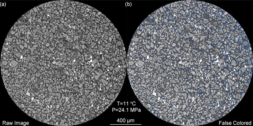
62                                             Y. Seol et al.: Tools for pressure core sub-coring and pore-scale micro-CT scans

Figure 2. General operations for pressure core manipulation (mod-
ified from Santamarina et al., 2012). The manipulator module in-
cludes manipulator, temporary storage chamber and ball valve.

                                                                       Figure 4. Sub-coring of cut pressure core and mini-core transfer
                                                                       into micro-CT scanning assembly that includes small ball valve,
                                                                       chamber adapter, and beryllium core holder. (a) Assemble the sub-
                                                                       coring components and attach them to the chamber that contains
                                                                       the cut pressure core; (b) open the ball valve and advance and drill
                                                                       through the pressure core; (c) advance the drill bit now containing
                                                                       the mini-core to pass the small ball valve and use the center rod
                                                                       in the inner layer to push the mini-core out of the drill bit towards
                                                                       the end of the beryllium core holder; (d) retract the drill back to
                                                                       its original position. Note the anti-slip pad and its location in the
Figure 3. Pressure cores being cut to appropriate lengths and trans-   sub-coring chamber (green frame in panel a).
ferred into the sub-coring chamber. (a) Equilibrate the pressure in
all the components; (b) push the pressure core to the predetermined
position and cut it; (c) push the pressure core to the sub-coring
chamber; (d) retrieve the remaining pressure core into the tempo-
rary storage chamber.                                                  rated up to 6170 psi with the diameter of window 14.0 mm
                                                                       (0.55 in). There is an anti-slip pad with teeth of sharpened
                                                                       screws in a radial pattern outside the center sampling area
core inside the sub-coring chamber is ready for sub-coring             penetrating the pressure core and resisting the rotation of
(Fig. 4a). The sub-coring tool consists of three main layers:          the core while drilling. To subsample the pressure core, the
the outer shell that holds the pressure, the middle layer and          rotating and pushing of the drill bit occur simultaneously
connected drill bit to drill a mini-core from the pressure core,       with different combinations according to the properties of the
and the inner layer that pushes the drilled mini-core into the         core. For a hard core such as sandstone, a higher rotation-to-
micro-CT scanning assembly. The standard drill bit is de-              advance ratio is recommended. For soft sediments, the drill
signed to cut hard cores and made of 316 stainless steel,              bit can be punched through the sediment without rotation.
with an ID of 9.35 mm (0.368 in), OD of 12.7 mm (0.5 in)               After the drill bit cuts through the core (Fig. 4b), the drill
and depth of 163.8 mm (6.45 in). The OD of the drill bit tip           bit continues to advance through the small ball valve with
(63.5 mm or 2.5 in, longer than the expected mini-core) can            the mini-core in it. Then the center rod pushes the axial con-
reduce to eliminate sample disturbance in softer cores, e.g.,          straint pad against the mini-core to send the mini-core to the
10.57 mm (0.416 in) when pushing through hydrate-bearing               beryllium core holder (Fig. 4c). The axial constraint pad is
pressure cores. Note that the advancing and rotating of the            left inside the micro-CT scanning assembly to provide ax-
drill bit are independent in this design, driven by specially          ial support for the mini-core during hydrological–mechanical
designed wrenches and manually operated handles (Fig. 1c               testing, and its length is pre-determined according to the
and d).                                                                length of the obtained mini-core. Both the center rod and the
   The drill bit is first pushed against the core without being        drill bit are retracted from the small ball valve so that the
rotated, which can also be observed from the viewport on the           small ball valve can be closed to secure the pressure inside
sides (Fig. 1f). The viewports (Encole LLC, NPT 3/4) are               the micro-CT scanning assembly (Fig. 4d). The pressure in

Sci. Dril., 29, 59–67, 2021                                                                   https://doi.org/10.5194/sd-29-59-2021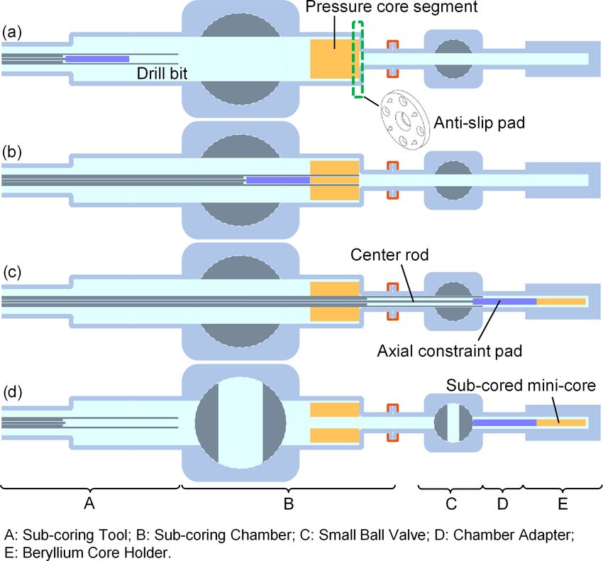
Y. Seol et al.: Tools for pressure core sub-coring and pore-scale micro-CT scans                                                      63

                                                                   Figure 6. Mini-cores drilled under pressure with this set of tools.
Figure 5. Micro-CT scan of a mini-core under pressure and tem-     (a) Two mini-cores at the top show the capability of this tool to drill
perature control.                                                  through hard sandstones. (b) Mini-core sampled by drilling through
                                                                   a segment of the pressure core.

the sub-coring chamber can be released to dissociate hydrate
in the residual pressure core after sub-coring.                    formation, dissociation and mechanical testing on hydrate-
   The micro-CT scanning assembly is designed to conduct           bearing sediments with laboratory-synthesized cores can be
triaxial testing; therefore, the axial support of the mini-core    found in Lei and Seol (2020) and Lei et al. (2019a, b).
against the pushing pad is critical. Note that the other end of
the pushing pad is against the ball of the small ball valve.
                                                                   3     Results
Therefore, the main body and tail of the pushing pad are
made of aluminum and a thin layer of Teflon (1/16 in or            3.1    Sub-coring under pressure
1.6 mm) to increase the stiffness of the pushing pad and pre-
vent scratching of the ball valve surface.                         Sub-coring was successful on both hard sandstone and soft
                                                                   hydrate-bearing sediments under targeted pressure and tem-
2.4   Micro-CT scan of mini-cores                                  perature conditions (Fig. 6), which demonstrates the capabil-
                                                                   ity of this set of tools. When drilling through a hard sandstone
The micro-CT scanning assembly containing the mini-core            core, the mini-core broke into two segments during drilling
is detached from the sub-coring tool (Fig. 5a) before it is        due to shear-induced cracks (Fig. 6a), but this would not af-
transferred and mounted on the rotary stage in the micro-          fect the micro-CT scanning as a piece of intact sample larger
CT scanner (Fig. 5b). Temperature and pressure controls are        than 3 mm3 is sufficient for a pore-scale micro-CT scan. As
required to maintain the stability of gas hydrate in the mini-     for natural hydrate-bearing sediments, the original pressure
core. A Peltier plate is used to control the temperature during    core degraded during the long-term (∼ 2 years) storage and
CT scanning by transferring heat from the micro-CT scan-           recent manipulations before the sub-coring. Therefore, the
ning chamber and dissipating the heat into the environment.        drill bit was pushed through the pressure core without any
The plate should be turned on at least 1 h before the mini-        rotation, and the obtained mini-core did not have a perfect
core transfer so that the rotary stage is pre-chilled to reduce    column shape (Fig. 6b), but there are intact blocks of hydrate-
temperature disturbance to the mini-core. One ISCO high-           bearing sediments in this mini-core, which is large enough to
pressure syringe pump is connected to both the top pore            capture the stratigraphic features in the radiographic image,
pressure line and confining fluid line to maintain the fluid       proving its sub-coring capability.
pressure. Such a configuration does not apply any effective
stress on the core. Micro-CT scans are conducted to obtain
                                                                   3.2    Pore-scale imaging of hydrate-bearing sediments
3D structures of the mini-core. Note that the pressure line
and power cables for the Peltier plate are all flexible to allow   Figure 7 shows 3D high-resolution micro-CT images of a
the rotation of the micro-CT scanning assembly during CT           mini-core from natural gas hydrate-bearing sediments. Three
scans.                                                             different phases including sediment particles, pore fluid and
   Detailed CT scan configuration and image processing are         natural gas hydrate can be identified at pore scale. The voxel
covered in Lei et al. (2018). Previous results of hydrate          size is 2.3 µm, and sediment particle sizes range from 20 to

https://doi.org/10.5194/sd-29-59-2021                                                                    Sci. Dril., 29, 59–67, 2021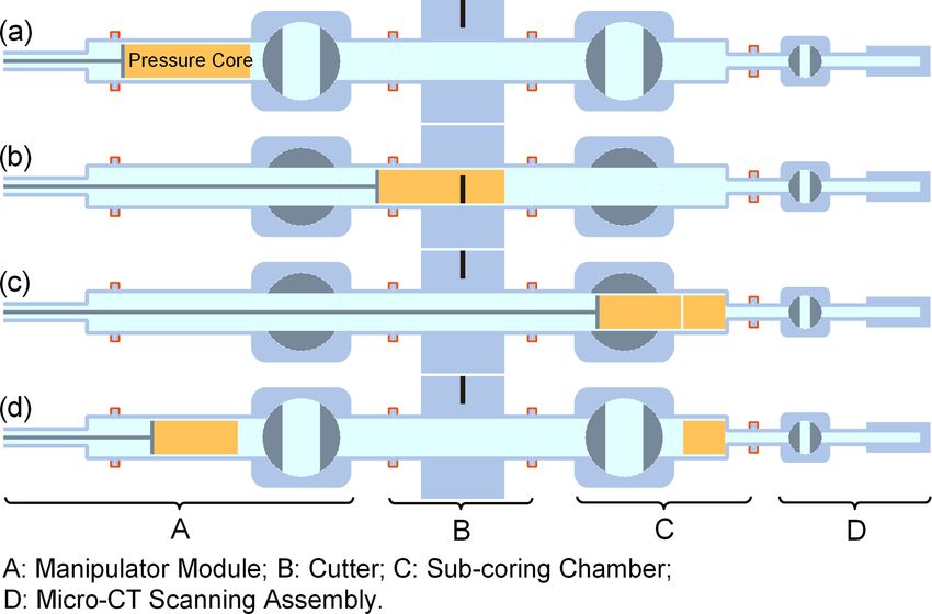
64                                             Y. Seol et al.: Tools for pressure core sub-coring and pore-scale micro-CT scans

                                                                        can easily penetrate the core but do not affect the mini-core
                                                                        quality. When the drill bit is punched through the pressure
                                                                        core, we risk both compression against the core and shear
                                                                        at the side of the mini-core, which is challenging to analyze.
                                                                        Sample disturbance is unavoidable during the coring process.
                                                                        However, for the purpose of visualization of pore-scale hy-
                                                                        drate distribution, a small piece of the well-preserved core
                                                                        as seen in both mini-cores in Fig. 6 is sufficient, proving the
                                                                        toolset successfully serves its designated purpose.

                                                                        4.2   Toolset features
Figure 7. One slice of the 3D image obtained from the micro-CT
scan of subsampled natural hydrate-bearing sediments: (a) raw im-       This set of tools has several features that facilitate the pore-
age and (b) false-colored image (hydrate in blue; note that the noise   scale micro-CT scanning.
in the raw image is preserved).
                                                                         1. Small mini-core diameter (9.5 mm). This core diameter
                                                                            enables high-resolution micro-CT scanning with a res-
50 µm. Note that the pore fluid contains some sodium iodide                 olution of 2 µm, therefore allowing for natural gas hy-
(NaI) salt. The fluid in the core space of the micro-CT scan-               drate identification in pore sizes of 20 µm.
ning chamber contained 7 wt % of KI initially before the core
                                                                         2. Applicable on a wide range of cores. As demonstrated,
holder received the mini-core, and this salt concentration is
                                                                            this tool can subsample mini-cores from both hard and
higher than the 5 wt % in our previous publication (Lei et al.,
                                                                            soft cores.
2018). This 7 wt % of salt concentration was selected consid-
ering fluid mixing with the original pore fluid in the sediment          3. Simple and robust core transfer mechanism. The drilling
and fluid exchange with the sub-coring chamber filled with                  and pushing of the mini-core with this set of tools are
deionized water so that the salt concentration of the pore fluid            along a straight line and only involve the drill bit ad-
decreases when the system reaches equilibrium. According                    vancing to deliver the mini-core to the micro-CT scan-
to the attenuation coefficient analysis based on the effective              ning assembly.
X-ray spectrum, the brightness of sediment particles, pore
fluid and gas hydrate decreases in that order; therefore, the            4. Manual handles in the drilling process. Manual con-
darkest spot in the raw CT image is gas hydrate.                            trols on drill rotation and advancement during the sub-
                                                                            coring process allow operators to get a direct sense of
                                                                            stress and resistance, thus reducing the likelihood of
4     Discussion                                                            damage/breakage of the mini-core and original pressure
                                                                            core.
4.1    Sample disturbance
                                                                         5. Anti-slip pad during sub-coring. The teeth sticking into
Sample disturbance is present in any sampling technique, as
                                                                            the pressure core during the drilling process can fix the
the sampling process is inherently associated with different
                                                                            position of the original pressure core while the drill bit
sources of disturbance, including change in effective stress
                                                                            rotates. This approach utilizes the compression between
and pore fluid pressure, sample transportation and storage,
                                                                            the drill bit and the core and therefore requires no addi-
sample manipulation before testing and so forth (Baligh et
                                                                            tional pressure core-grabbing mechanism.
al., 1987; Rochelle et al., 1981; Sheng and Carlos, 2014).
In the two sub-coring practices with this toolset, there is              6. No additional cutting on the mini-core is required af-
clear evidence of sample disturbance. When the hard sand-                   ter the drilling process when compared with the tools
stone is used, the drilled mini-core breaks into two segments,              reported in Parkes et al. (2009).
as shown in Fig. 6a. This is very likely due to the friction
between the drill bit and the mini-core, and the mini-core               7. Drilling through the center of the pressure core. An al-
breaks when the drilling torque exceeds the lateral shear                   ternative strategy is to drill through the side of the pres-
strength of the mini-core. Similar phenomena are often seen                 sure core, which involves drilling through the plastic
in pressure cores (Dai and Santamarina, 2014; Jang et al.,                  core sleeve outside the pressure core. There would be
2019b; Fang et al., 2020). Meanwhile, the four teeth on the                 a piece of plastic at the end of the mini-core, which pre-
anti-slip pad damage the surface of the sandstone, but the                  vents axial permeability measurements. Furthermore,
damage occurs on the outer residual portion of the sample                   to conduct a permeability test, the alternative strategy
and therefore does not affect the quality of the mini-core                  needs a mechanism to remove the plastic liner from the
taken from the center. As for the soft sediments, the four teeth            mini-core end.

Sci. Dril., 29, 59–67, 2021                                                                  https://doi.org/10.5194/sd-29-59-2021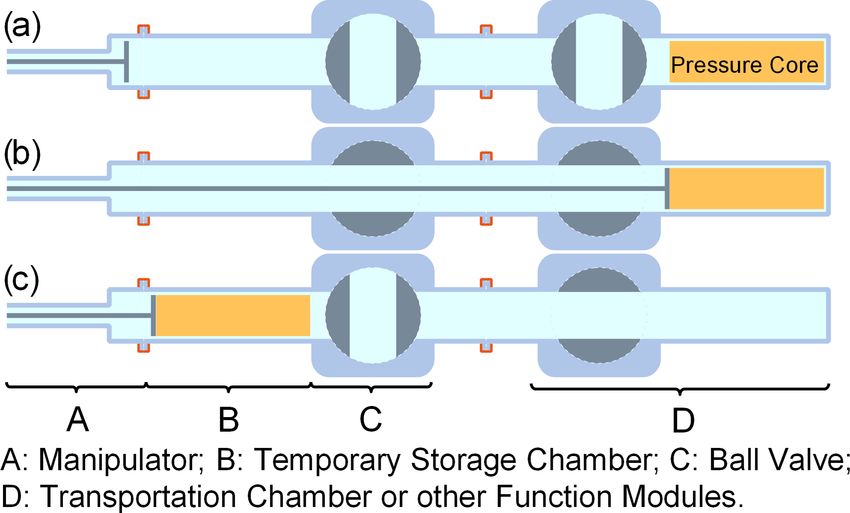
Y. Seol et al.: Tools for pressure core sub-coring and pore-scale micro-CT scans                                                    65

  8. Precise control of the mini-core position after core           sorption, complexation, and dissolution reactions of the com-
     transfer. All the other existing techniques simply push        ponents. Those observations can also be applicable to con-
     the mini-core into the next testing chamber (Jin et al.,       ventional energy-related fields such as oil recovery, geologic
     2014; Parkes et al., 2009; Schultheiss et al., 2009),          carbon storage and diverse environmental remedial technolo-
     therefore not having control of the mini-core position.        gies.
     The procedure in this study pushes the mini-core into             Indirect applications. Any applications that require sub-
     the rubber sleeve which is at the center of the micro-CT       coring processes within an isolated environment could use
     scanning assembly.                                             the procedure described here. Since the chamber used in this
                                                                    application could be a barrier for pressure, heat, electrical
  9. Permeability and mechanical testing of the mini-core           current or any other physical, chemical or biological changes,
     are achievable. The micro-CT scanning assembly has a           the procedure described herein could be used with minor
     rubber sleeve (Fig. 1f) separating the mini-core and con-      modifications.
     fining fluid to enable the application of lateral confining
     pressure and a functional end piece that can hydrauli-         5   Conclusions
     cally drive a piston to apply axial pressure. Influent and
     effluent ports allow for flowing fluid through the mini-       This work presents a series of tools that enable the ma-
     core (further details in Seol et al., 2019). This permits      nipulation, transfer, cutting, sub-coring and CT scanning at
     hydrological and mechanical testing of the mini-core,          both core and pore scale of pressure cores while maintaining
     although these tests were not conducted in this study          pressure and temperature controls. The mini-cores created
     due to the quality of the degraded pressure core.              demonstrate that the sub-coring tool can drill through both
                                                                    hard and soft sediments under pressure and provide adequate
4.3   Potential applications                                        samples with intact segments. This set of tools along with the
                                                                    testing procedure allows for the investigation of pore habits
Direct application. Gas hydrate in nature contains a large          of natural gas hydrate within the sediment matrix. Further-
amount of natural gas (Boswell and Collett, 2011; Milkov,           more, this set of tools can be used for other potential opera-
2004). Therefore, if commercial gas production is achieved,         tions that require environmental controls throughout all steps
gas hydrate has the potential to expand the worldwide energy        of operation.
supply. Pore habits within single pores and inter-pore distri-
bution of gas hydrate in sediments reflect formation histories
(Lei et al., 2019a); therefore, they can vary in different reser-   Data availability. No data sets were used in this article.
voirs. Major energy consumers and importers such as the US,
China, Japan and India are investing extensively in hydrate
pressure core research, targeting commercial gas production.        Author contributions. YS, KJ, DH, and JHC provided the func-
This set of tools provides pore-scale insight into the reser-       tion and technical requirement and contributed to the original de-
voir, which helps us to understand the behavior of hydrate          sign. GW, BG, and CM conducted the initial engineering design.
during formation, evolution and production. Physical prop-          LL, YS, KJ, JHC, TP, and XG performed the instrument shake-
erties such as permeability, thermal conductivity, mechani-         down, contributed to the design modification, and conducted related
                                                                    experiments. DH modified the engineering design towards the fi-
cal stiffness and strength are highly dependent on the pore
                                                                    nal form. LL prepared the manuscript. All the coauthors edited the
habits and distribution of gas hydrate in the sediment ma-
                                                                    manuscript. YS managed the project.
trix. These properties are key input parameters to predict gas
production rates and evaluate the cost–benefit ratio through
reservoir simulations. Therefore, this sub-coring process and       Competing interests. The authors declare that they have no con-
the subsequent micro-CT studies it enables are needed prior         flict of interest.
to pursuing direct field tests for gas production, especially
when offshore operations are involved. Such pore-scale 3D
studies help to reveal the interactive nature of hydrate crys-      Acknowledgements. Liang Lei, Xuerui Gai, and Taehyung Park
tals with sediment matrices and their mechanical integrity as       are supported under an Oak Ridge Institute for Science and Edu-
well as to acquire reliable quantitative prediction of reservoir    cation (ORISE) fellowship granted by NETL. Karl Jarvis (LRST)
productivity.                                                       and Jeong-Hoon Choi (LRST) conducted this work under RSS con-
   The tools, used together with the micro-CT scanner, en-          tract 89243318CFE000003. Pressure core samples were obtained
able monitoring of the multiphase fluid’s behaviors in a            from the UT-GOM2-1 Hydrate Pressure Coring Expedition which
porous medium as the physicochemical substances change              was funded by Department of Energy Award DE-FE0023919 and
                                                                    advised by the United States Geological Survey (USGS) and the
in a chamber. Direct observations of dynamic flow patterns
                                                                    Bureau of Ocean Energy Management (BOEM).
of immiscible fluids, such as oil and brine or CO2 with brine,
are attainable through micro-CT analysis in responses to ad-

https://doi.org/10.5194/sd-29-59-2021                                                                    Sci. Dril., 29, 59–67, 2021
66 Y. Seol et al.: Tools for pressure core sub-coring and pore-scale micro-CT scans
Financial support. This research has been supported Jang, J., Waite, W. F., Stern, L. A., Collett, T. S., and Kumar, P.:
by the National Energy Technology Laboratory (grant Physical property characteristics of gas hydrate-bearing reservoir
no. 89243318CFE000003) and the U.S. Department of En- and associated seal sediments collected during NGHP-02 in the
ergy (grant no. DE-FE0023919). Krishna-Godavari Basin, in the offshore of India, Mar. Pet. Geol.,
108, 249–271, https://doi.org/10.1016/j.marpetgeo.2018.09.027,
2019a.
Review statement. This paper was edited by Thomas Wiersberg Jang, J., Dai, S., Yoneda, J., Waite, W. F., Stern, L. A., Boze,
and reviewed by two anonymous referees. L.-G., Collett, T. S., and Kumar, P.: Pressure core analy-
sis of geomechanical and fluid flow properties of seals as-
sociated with gas hydrate-bearing reservoirs in the Krishna-
Godavari Basin, offshore India, Mar. Pet. Geol., 108, 537–550,
https://doi.org/10.1016/j.marpetgeo.2018.08.015, 2019b.
References Jin, Y., Konno, Y., and Nagao, J.: Pressurized subsampling system
for pressured gas-hydrate-bearing sediment: Microscale imag-
Amann, H., Hohnberg, H.-J., and Reinelt, R.: HYACE – A novel ing using X-ray computed tomography, Rev. Sci. Instrum., 85,
autoclave coring equipment for systematic offshore gas hy- 094502, https://doi.org/10.1063/1.4896354, 2014.
drate sampling, Gas Hydrates: Problems Substance/Resource, Kvenvolden, K. A., Barnard, L. A., and Cameron, D. H.: Pressure
Clausthal-Zellerfeld (Harz), Germany, 1997. core barrel: Application to the study of gas hydrates, Deep Sea
Baligh, M. M., Azzouz, A. S., and Chin, C. T.: Disturbances Due Drilling Project Site 533, Leg 76, Washington, D.C., USA, 367–
to “Ideal” Tube Sampling, J. Geotech. Eng., 113, 739–757, 375, 1983.
https://doi.org/10.1061/(ASCE)0733-9410(1987)113:7(739), Lei, L. and Seol, Y.: Pore-scale investigation of methane hydrate-
1987. bearing sediments under triaxial condition, Geophys. Res. Lett.,
Boswell, R.: Is gas hydrate energy within reach?, Science, 325, 47, e2019GL086448, https://doi.org/10.1029/2019GL086448,
957–958, https://doi.org/10.1126/science.1175074, 2009. 2020.
Boswell, R. and Collett, T. S.: Current perspectives on gas Lei, L., Seol, Y., and Jarvis, K.: Pore-scale visualization of methane
hydrate resources, Energy Environ. Sci., 4, 1206–1215, hydrate-bearing sediments with micro-CT, Geophys. Res. Lett.,
https://doi.org/10.1039/C0EE00203H, 2011. 45, 5417–5426, https://doi.org/10.1029/2018GL078507, 2018.
Boswell, R., Frye, M., Shelander, D., Shedd, W., McConnell, D. R., Lei, L., Seol, Y., Choi, J.-H., and Kneafsey, T. J.: Pore habit of
and Cook, A.: Architecture of gas-hydrate-bearing sands from methane hydrate and its evolution in sediment matrix – Labora-
Walker Ridge 313, Green Canyon 955, and Alaminos Canyon 21: tory visualization with phase-contrast micro-CT, Mar. Pet. Geol.,
Northern deepwater Gulf of Mexico, Mar. Pet. Geol., 34, 134– 104, 451–467, https://doi.org/10.1016/j.marpetgeo.2019.04.004,
149, https://doi.org/10.1016/j.marpetgeo.2011.08.010, 2012. 2019a.
Collett, T. S., Kumar, P., Boswell, R., and Waite, W. F.: Pref- Lei, L., Seol, Y., and Myshakin, E. M.: Methane hydrate film thick-
ace: Marine gas hydrate reservoir systems along the East- ening in porous media, Geophys. Res. Lett., 46, 11091–11099,
ern Continental Margin of India: Results of the National Gas https://doi.org/10.1029/2019GL084450, 2019b.
Hydrate Program Expedition 02, Mar. Pet. Geol., 108, 1–2, Makogon, Y. F.: Hydrates of hydrocarbons, Pennwell Books, Pen-
https://doi.org/10.1016/j.marpetgeo.2019.03.005, 2019. nWell Publishing Company, Tulsa, Oklahoma, USA, 1997.
Dai, S. and Santamarina, J. C.: Sampling disturbance in hydrate- Milkov, A. V.: Global estimates of hydrate-bound gas in marine sed-
bearing sediment pressure cores: NGHP-01 expedition, Krishna– iments: how much is really out there?, Earth-Sci. Rev., 66, 183–
Godavari Basin example, Mar. Pet. Geol., 58, 178–186, 197, https://doi.org/10.1016/j.earscirev.2003.11.002, 2004.
https://doi.org/10.1016/j.marpetgeo.2014.07.013, 2014. Parkes, R. J., Sellek, G., Webster, G., Martin, D., Anders, E.,
Dai, S., Santamarina, J. C., Waite, W. F., and Kneafsey, T. J.: Weightman, A. J., and Sass, H.: Culturable prokaryotic diver-
Hydrate morphology: Physical properties of sands with patchy sity of deep, gas hydrate sediments: first use of a continuous
hydrate saturation, J. Geophys. Res.-Sol. Ea., 117, B11205, high-pressure, anaerobic, enrichment and isolation system for
https://doi.org/10.1029/2012JB009667, 2012. subseafloor sediments (DeepIsoBUG), Environ. Microbiol., 11,
Dickens, G. R., Schroeder, D. K., Hinrichs, U., and the Leg 201 3140–3153, https://doi.org/10.1111/j.1462-2920.2009.02018.x,
Scientific Party: The pressure core sampler (PCS) on ODP 2009.
Leg201: General operations and gas release, in: Proc.ODP, Init. Pettigrew, T. L.: Design and operation of a wireline Presure Core
Repts., College Station, TX (Ocean Drilling Program), edited by: Sampler (PCS), Texas A&M University, College Station, Texas,
D’Hondt, S. L., Jøgensen, B. B., Miller, D. J., et al., 201, 1–22, USA, 1992.
https://doi.org/10.2973/odp.proc.ir.201.103.2003, 2003. Priest, J. A., Hayley, J. L., Smith, W. E., Schultheiss, P., and
Fang, Y., Flemings, P. B., Daigle, H., Phillips, S. C., Meazell, P. Roberts, J.: PCATS triaxial testing: Geomechanical properties of
K., and You, K.: Petrophysical properties of the GC 955 hydrate sediments from pressure cores recovered from the Bay of Ben-
reservoir inferred from reconstituted sediments: Implications for gal during expedition NGHP-02, Mar. Pet. Geol., 108, 424–438,
hydrate formation and production, AAPG Bull., 104, 1997–2028, https://doi.org/10.1016/j.marpetgeo.2018.07.005, 2019.
https://doi.org/10.1306/01062019165, 2020. Qin, H., Gu, L., Li, S., Zhu, L., and Chen, Y.: Pressure tight pis-
Flemings, P. B., Phillips, S. C., Collett, T., Cook, A., Boswell, R., ton corer – A new approach on gas hydrate investigation, China
and the UT-GOM2-1 Expedition Scientists: UT-GOM2-1 Hy- Ocean Eng., 19, 121–128, https://doi.org/10.3321/j.issn:0890-
drate Pressure Coring Expedition Summary, University of Texas 5487.2005.01.011, 2005.
Institute for Geophysics, Austin, TX, USA, 2018.
Sci. Dril., 29, 59–67, 2021 https://doi.org/10.5194/sd-29-59-2021Y. Seol et al.: Tools for pressure core sub-coring and pore-scale micro-CT scans 67 Rochelle, P. L., Sarrailh, J., Tavenas, F., Roy, M., and Ler- Yamamoto, K.: Overview and introduction: Pressure core- oueil, S.: Causes of sampling disturbance and design of a sampling and analyses in the 2012–2013 MH21 offshore new sampler for sensitive soils, Can. Geotech. J., 18, 52–66, test of gas production from methane hydrates in the https://doi.org/10.1139/t81-006, 1981. eastern Nankai Trough, Mar. Pet. Geol., 66, 296–309, Santamarina, J. C., Dai, S., Jang, J., and Terzariol, M.: Pressure https://doi.org/10.1016/j.marpetgeo.2015.02.024, 2015. Core Characterization Tools for Hydrate-Bearing Sediments, Yoneda, J., Oshima, M., Kida, M., Kato, A., Konno, Y., Jin, Y., Sci. Dril., 14, 44–48, https://doi.org/10.2204/iodp.sd.14.06.2012, Jang, J., Waite, W. F., Kumar, P., and Tenma, N.: Pressure 2012. core based onshore laboratory analysis on mechanical properties Santamarina, J. C., Dai, S., Terzariol, M., Jang, J., Waite, W. of hydrate-bearing sediments recovered during India’s National F., Winters, W. J., Nagao, J., Yoneda, J., Konno, Y., Fu- Gas Hydrate Program Expedition (NGHP) 02, Mar. Pet. Geol., jii, T., and Suzuki, K.: Hydro-bio-geomechanical properties of 108, 482–501, https://doi.org/10.1016/j.marpetgeo.2018.09.005, hydrate-bearing sediments from Nankai Trough, Mar. Pet. Geol., 2018. 66, 434–450, https://doi.org/10.1016/j.marpetgeo.2015.02.033, Yoneda, J., Oshima, M., Kida, M., Kato, A., Konno, Y., 2015. Jin, Y., Jang, J., Waite, W. F., Kumar, P., and Tenma, Schultheiss, P., Holland, M., and Humphrey, G.: Wireline Cor- N.: Permeability variation and anisotropy of gas hydrate- ing and Analysis under Pressure: Recent Use and Future De- bearing pressure-core sediments recovered from the Krishna– velopments of the HYACINTH System, Sci. Dril., 7, 44–50, Godavari Basin, offshore India, Mar. Pet. Geol., 108, 524–536, https://doi.org/10.2204/iodp.sd.7.07.2009, 2009. https://doi.org/10.1016/j.marpetgeo.2018.07.006, 2019. Seol, Y., Lei, L., Choi, J.-H., Jarvis, K., and Hill, D.: Integra- Yun, T. S., Santamarina, J. C., and Ruppel, C.: Mechani- tion of triaxial testing and pore-scale visualization of methane cal properties of sand, silt, and clay containing tetrahy- hydrate bearing sediments, Rev. Sci. Instrum., 90, 124504, drofuran hydrate, J. Geophys. Res.-Sol. Ea., 112, B04106, https://doi.org/10.1063/1.5125445, 2019. https://doi.org/10.1029/2006JB004484, 2007. Sheng, D. J. and Carlos, S.: Sampling disturbance in hydrate- Yun, T. S., Lee, C., Lee, J.-S., Bahk, J. J., and Santa- bearing sediment pressure cores: NGHP-01 expedition, Krishna– marina, J. C.: A pressure core based characterization of Godavari Basin example, Mar. Pet. Geol., 58, 178–186, hydrate-bearing sediments in the Ulleung Basin, Sea of https://doi.org/10.1016/j.marpetgeo.2014.07.013, 2014. Japan (East Sea), J. Geophys. Res.-Sol. Ea., 116, B02204, Sloan, E. D. and Koh, C. A.: Clathrate hydrates of natural gases https://doi.org/10.1029/2010JB007468, 2011. (Third edition), edited by: Speight, J. G., CRC Press, Boca Raton, Zhang, G., Yang, S., Zhang, M., Liang, J., Lu, J., Holland, M., and FL, USA, 752 pp., 2007. Schultheiss, P.: GMGS2 expedition investigates rich and com- Waite, W. F., Santamarina, J. C., Cortes, D. D., Dugan, B., Espinoza, plex gas hydrate environment in the South China Sea, Fire in the D. N., Germaine, J., Jang, J., Jung, J. W., Kneafsey, T. J., Shin, Ice, 14, 1–5, 2014. H., Soga, K., Winters, W. J., and Yun, T. S.: Physical proper- ties of hydrate-bearing sediments, Rev. Geophys., 47, RG4003, https://doi.org/10.1029/2008RG000279, 2009. https://doi.org/10.5194/sd-29-59-2021 Sci. Dril., 29, 59–67, 2021
You can also read