Off-gas energy valorisation in high-performance electric arc furnaces
←
→
Page content transcription
If your browser does not render page correctly, please read the page content below
Clean technologies in steelmaking

         Off-gas energy valorisation in
     high-performance electric arc furnaces
                                     A. Foresti, S. Santarossa, N. Monti, G. Di Zanni, C. Milo

The growing share of steel produced worldwide with EAFs is helping the industry to reduce emissions and meet the ambitious Carbon
Emission Reduction Target agreed internationally.
Electric Steelmakers can further improve their energy efficiency and reduce emissions by recovering the residual heat energy of their
melting processes which is commonly wasted.
Converting the EAF off-gas heat into power has been demonstrated to be practical and effective with the first 2.7 MW (electric power)
ORC system at Elbe Stahlwerke Feralpi (Germany) operating since 2013. A similar ORC system was then installed at ORI Martin (Italy)
and a third one supplied supplied in Japan.
The experience of these plants led Arvedi to install a new evaporative EAF cooling system and a much larger ORC unit (7 MW net
electric power) for its new investment program to render the EAF-based facilities in Cremona one of the most energy efficient steel
plants in Europe.
The paper describes the Arvedi project comparing it with the previous EAF heat recovery systems by Tenova and Turboden.

     KEYWORDS: ENERGY EFFICIENCY – EAF - STEELMAKING - HEAT RECOVERY – OFF-GAS - STEAM GENERATION -
                                   ORC - CONSTEEL® - IRECOVERY®

INTRODUCTION: ENERGY EFFICIENCY IN MINI-MILLS                          scarcity of indigenous fossil fuels, forced Italian mini-mill ope-
Recycling ferrous scrap and melting it in high-performance             rators to concentrate their efforts on increasing the energy ef-
electric furnaces is the most appropriate route to recover avai-       ficiency of their plants and processes in order to compete with
lable iron units. It is the most energy efficient steelmaking pro-     steelmakers enjoying lower power costs elsewhere in Europe.
cess with minimum greenhouse gas emissions.                            The flexibility of EAF based mini-mills and the continuous im-
In the 70 years after World War II the Italian steel industry grew     provements made possible with many smaller scale investments
with two different models.                                             compared to the large scale BF–BOF integrated steel plants,
The first model followed the US and then Japanese models with          have allowed Italy’s private-sector steelmakers based on scrap
integrated (BF-BOF) steel plants installed along the coast with        recycling to become important players in Europe.
ports capable of receiving ocean-going bulk carriers with im-          European plant makers have had a major role in advancing pro-
ported raw materials typically coming from the Americas (iron          cess technologies in EAF steel melting as well as in continuous
ore from Brazil, coking coal from USA). The best and largest           casting and rolling to optimize yield, productivity and energy
plant of this type in Italy is in Taranto, originally built with in-   efficiency.
vestment by the Italian state - owned by IRI group - to promote        The technology breakthrough of thin slab continuous casting
industrialization in the depressed southern part of the country
through the production of flat hot-rolled carbon and low-alloy
steel coils and plates. Taranto and other sites competed mostly
with the major (BF-BOF) integrated plants in Germany, France,
Benelux, Spain and Austria.
The second model, recycling scrap in the EAF, was later known                           A. Foresti, S. Santarossa
as the “mini-mill”. After the end of the war, private entrepre-                               Turboden S.p.A., Italy
neurs, typically active in the recovery of ferrous scrap, installed
                                                                                          N. Monti, G. Di Zanni
small plants initially in Northern Italy, near Brescia, to produ-                              Tenova S.p.A., Italy
ce mostly reinforcing bar for the construction industry. These
steelmaking companies, often family-controlled, grew over the                                       C. Milo
years, investing in new units and plant updates to increase                               Acciaieria Arvedi S.p.A., Italy
volumes, product range and quality to cover at least half of
the Italian steel market and the vast majority of long products.
The traditional high costs of energy in Italy, due to the lack or

18                                                                                                     La Metallurgia Italiana - n. 5 2019
Tecnologie pulite per la produzione d’acciaio
with in line rolling has allowed the product range of scrap- Arvedi cast-rolling technology was designed and patented by
based mini-mills to expand and include flat products. With this Giovanni Arvedi and first installed at the Acciaieria Arvedi wor-
development, mini-mills based on EAF scrap melting in the US, ks in Cremona in 1992 with an ISP line. The technology was fur-
in Italy and elsewhere have been able to compete with the lar- ther developed and in 2009 an ESP line was installed, built and
ge continuous hot strip mills typical of large BF-BOF integrated automated by Primetals Technologies (formerly Siemens VAI),
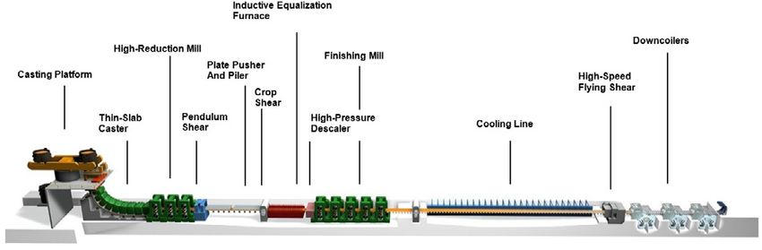
steel plants to produce carbon and low-alloy steel flats. the world’s first truly endless strip production plant (Fig. 1).
Fig. 1 – Arvedi ESP Caster mill configuration.
In only 180 meters from the mold to the down-coiler and in just In 2009 Tenova commissioned at the GMH steel plant in Ge-
6-7 minutes from the liquid steel to the hot-rolled coil Arvedi orgsmarienhütte, Germany the first EAF off-gas heat recovery
ESP technology, linking casting and rolling directly, has taken installation based on ECS (Evaporative Cooling System). The
strip production to an entirely new level. The process is unique 140-t DC EAF had been installed at the site in 1996, replacing
for its fully endless strip production mode and utilization of the an older, dismantled BOF converter. The new saturated steam
slab’s internal heat energy, leading to lower capital expenditure system took advantage of the previous experience gained at
and operational costs compared to conventional linked casting the site. The EAF energy recovery system, later called iRecove-
and rolling plants that use gas-fired roller reheating furnaces. ry®, allows the generation of saturated steam (20 t/h avg. at
The history of Italian EAF mini-mills, such as Arvedi’s outlined 13-20 bar) to be used for various tasks including ejectors for
above, explains the development of highly efficient scrap-based vacuum degassing (1).
mini-mills in Italy and elsewhere in Europe. These plants are Other heat-only iRecovery® systems were then installed and
often considered benchmarks for electric steelmaking today. are operating at Hyundai Steel (Korea) and at TPCO (China).
High-performance EAFs ensure high productivity, maximum After the start-up in December 2013, the first EAF off-gas
yield and high energy efficiency: These optimum qualities are energy recovery system, including conversion of heat to power
the result of a continuous effort to improve the process and with ORC (Organic Rankine Cycle), began operating at the Elbe
operation practices. The logical further step to maximize energy Stahlwerke Feralpi in Riesa Germany. The iRecovery® system at
efficiency and reduce emissions in high-performing EAFs is to ESF recovers nominally 30 t/h of steam partly converted to 2.7
recover the residual heat contained in the off-gas with con- MW in the Turboden ORC and partly dispatched to an adjacent
tinuous charging and scrap preheating, generating steam or neighboring tyre-making plant (2).
hot water for large heat users, or finally by converting heat to Since 2016 a second iRecovery® system and Turboden ORC
power. unit has been operating at the ORI Martin steel plant in Brescia,
All of these options are effective if they are safe, automatically Italy, featuring a new improved Consteel® EAF. Also in this
controlled and maintain the reliability of the original EAF ope- case both heat and power are produced: steam serves the mu-
ration. nicipal district heating system in winter, while the ORC typically
converts heat to 1.8 MW outside the heating season (3).
EAF HEAT RECOVERY SYSTEMS A third system with iRecovery® and Turboden ORC unit sup-
Over the last ten years new off-gas heat recovery installations plied in Japan, is scheduled to start up in 2019.
retrofitted to existing high performing EAFs havedemonstrated A summary of the heat recovery systems with ORC supplied by
the feasibility of energy recovery and valorization in several Tenova and Turboden is shown below.
plants in Europe and the Far East.
La Metallurgia Italiana - n. 5 2019 19
Clean technologies in steelmaking
Tab. 1 – Heat recovery systems with ORC in EAF steelmaking.

                             HEAT RECOVERY SYSTEMS WITH ORC IN EAF STEELMAKING
                                                       Elbe Stahlwerke
                                                                           ORI Martin Brescia,   Arvedi Cremona,
     Components              Data            Unit           Feralpi                                                        Japan
                                                                                 Italy                Italy
                                                       Riesa, Germany

                        Tapping weight         t             100                   85                  250                  147
       Electric
       Furnace
                        Scrap charging         -           Baskets              Consteel             Consteel             Baskets

                                                         Radiation +                                                    Radiation +
                        Heat exchanger         -                               Convection           Convection
                                                         Convection                                                     Convection

       Waste              Heat carrier         -            Steam                Steam                Steam                Steam
        Heat
      Recovery             Pressure         bar g            27                    16                   16                   16
       System
                          Total steam
                          production          t/h            30                    16                   52                  33.6
                           (nominal)
                      Steam flow rate to
                                              t/h            20                    16                   52                  23.6
                      the ORC (nominal)

                                              °C             245                  200                  205                  205
                      Steam inlet condi-
                            tions
                                            bar g            27                    15                   16                   16
        ORC
                       Gross ORC active
                        electric power       KW             2,700                1,885                7,237                2,435
                            output
                       ORC captive con-
                                             KW              120                   64                  312                  105
                          sumption
                        Net ORC active
                        electric power       KW             2,580                1,821                6,925                2,330
                            output

ARVEDI IN STEEL                                                        process fully in-line (no intermediate buffer) for consistent high
Founded in 1963 with a tube mill and a steel products trading          quality ultrathin steel coils (0.8 mm) of homogenous quality,
company, the Arvedi Group is today a major European steel              with close tolerances and the very low energy use.
industry with a production of about 4 million t/y of steel coils       The Arvedi ESP line in Cremona is fed by a 250-t Consteel®
and tubes. The main facility in Cremona is the largest scrap-ba-       EAF. The combination of Consteel® EAF with continuous char-
sed steelmaking plant in Italy. It includes two electric furnaces      ging and scrap preheating plus ladle furnace refining with Ar-
feeding two separate thin slab casting and in-line hot rolling         vedi ESP in-line casting and rolling allows an extremely com-
plants to produce thin gauge steel coils, plus downstream lines        pact layout and short process time with the best conditions for
for pickling, cold rolling, galvanizing and pre-painting.              producing high volumes of quality steel flats with high yield
Both lines with in-line casting and hot rolling represent impor-       and good energy efficiency.
tant original innovations introduced by Arvedi. The first line,        The patented Arvedi ESP technology has been licensed for mul-
operating since 1992 called ISP (In-line Strip Production), inclu-     tiple similar lines installed recently in China.
des a buffer coil furnace (Cremona furnace) between the high           Giovanni Arvedi, founder of the Arvedi Group, is recognized
reduction mill and the finishing mill.                                 throughout the steelmaking world for the technological in-
The second line, with a capacity of 2.2 million t/y, called ESP        novations he has introduced into his plants. He is also a phi-
(Endless Strip Production), has been operating since 2010. ESP         lanthropist and the major donor for the Violin Museum recently
technology is a further innovative step of ISP. In fact, ESP al-       established in Cremona.
lows a continuous, endless (uninterrupted) casting and rolling         In 2015 Arvedi launched an important modernization program

20                                                                                                   La Metallurgia Italiana - n. 5 2019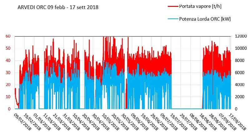
Tecnologie pulite per la produzione d’acciaio
to further optimize its processes and extend its product range      el® EAF includes the iRecovery® system for evaporative co-
and improve the energy efficiency and environmental perfor-         oling, the ORC to convert steam to power, the water-cooled
mance of its plants in Cremona and the newly acquired plant         condenser and auxiliaries.
in Trieste. This program, partly financed by the European In-       The iRecovery® system is mainly made up of a waste heat
vestment Bank with guarantees from the European Fund for            boiler that uses the thermal energy contained in the off-gas
Strategic Investment, involved replacing the original EAF instal-   coming from the Consteel® EAF furnace to heat the water and
led in 1992 to feed the ISP line. The new basket-charged EAF        convert it into steam.
includes a heat recovery system producing hot water to provide      The ORC module exploits the steam to produce electricity and
the heat necessary for the pickling lines downstream instead of     returns the condensate to the boiler, thus closing the water’s
a gas-fired boiler.                                                 thermal cycle.
Moreover, in order to further reduce energy consumption and         Since the temperature and flow-rate of the furnace fumes
the GHG emissions of the steel plant in Cremona, Arvedi deci-       change continuously during the furnace tapping cycle, the de-
ded to install a new state-of-the-art heat recovery system with     sign of the heat recovery system is optimized to receive fumes
power production on the 250-t Consteel® EAF feeding the ESP         continuously and to send steam to ORC constantly at the same
line.                                                               conditions of temperature and flow-rate.
The experience of the previous plants with iRecovery® and Tur-      The waste heat boiler is designed with the aim to recover an
boden ORC at ESF Riesa and ORI Martin Brescia, led Arvedi to        input power from the fumes of up to 90 MWth and to produce
choose a similar configuration with much bigger equipment,          steam up to 140 t/h. The output power of the steam to the ORC
realizing the largest ever EAF off-gas energy recovery system.      unit is controlled so as to be nearly constant with a nominal
                                                                    value of up to 52 t/h, equivalent to 34 MW of heat, to be con-
ARVEDI CONSTEEL® EAF HEAT RECOVERY                                  verted to up to 7.0 MW electric power (Fig. 2).
The off-gas heat recovery system at the Arvedi 250-t Conste-

Fig. 2 – Main process flow diagram of the iRecovery® system.

THE IRECOVERY® SYSTEM                                               quenching tower, the waste heat boiler can operate indepen-
Overview                                                            dently from the pre-existing off-gas system, so that the old off-
The waste heat boiler is installed in parallel to the existing      gas cooling system can be restored should a problem occur in
quenching tower; it receives the hot fumes from the drop-out-       the iRecovery system.
box located downstream of the Consteel® and conveys them            The operation of the iRecovery is automatic with no need for
into the existing primary off-gas line downstream of the quen-      continuous supervision by the steel plant operating personnel.
ching tower (Fig.3).                                                In case of fault, the waste heat boiler is safely switched off
The waste heat boiler includes an electric modulating damper,       automatically and the boiler is disconnected from the existing
installed on the exit side duct.                                    off-gas system.
Thanks to the combined control of the above-mentioned dam-          Basically, the iRecovery® System is composed of the following
per and the pre-existing damper located downstream of the           units:

La Metallurgia Italiana - n. 5 2019                                                                                               21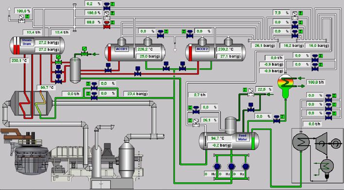
Clean technologies in steelmaking
- waste heat steam generator                                       The iRecovery® plant is located in two areas: one, outside the
- steam accumulation unit                                          EAF-Consteel building, is for the waste heat boiler; the other
- auxiliary condenser                                              one, inside a new building, is for all remaining equipment.
- feed water unit                                                  The ORC plant is placed in another adjoining building.

Fig. 3 – Waste heat boiler and quenching tower.

Waste heat steam generator                                         the outlet of the boiler downstream of the evaporators; thanks
The waste heat boiler is made up of a natural circulation boiler   to the economizers, the temperature of the off-gas coming out
which is equipped with:                                            of the evaporators can be further reduced;
− 5 evaporators consisting of vertical pipe bundles; the hot fu-   − automatic cleaning system that allows the cyclical separation
mes on impact with the pipes of the evaporator heat the water      of dust from the surfaces of the heat exchanger units;
circulating inside them;                                           − dust extraction system with chain conveyors to collect and
− 1 steam drum consisting of a horizontal cylindrical tank in-     carry off the dust;
stalled on the top side of the boiler; the evaporators receive     − 1 electric modulating damper, installed on the duct down-
the water from the bottom of the drum and deliver the boiling      stream of the waste heat boiler to regulate the gas flow-rate
water to it by flowing in a natural circulation way;               through the boiler.
− 1 economizer consisting of vertical pipe bundles, installed at

22                                                                                              La Metallurgia Italiana - n. 5 2019
Tecnologie pulite per la produzione d’acciaio
Tab. 2 – Waste heat boiler and quenching tower.
TECHNICAL DATA OF WASTE HEAT BOILER
Nominal power 90 MW
Maximum continuous steam production 138 t/h
Maximum nominal off-gas flow-rate 300,000 Nm3/h
Maximum nominal off-gas inlet temperature 900 °C
Maximum nominal off-gas outlet temperature 240 °C
PS (maximum allowable pressure) 30 bar
TS (maximum allowable temperature) 236 °C
Capacity 50 m3
Length 12 m
Height 20 m
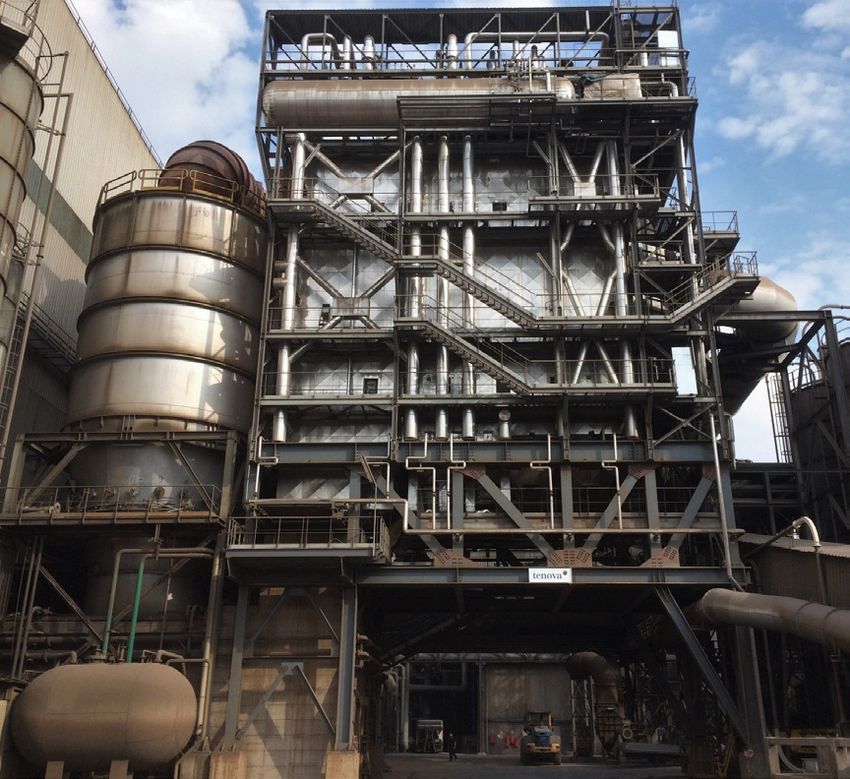
Steam accumulation unit On the downstream steam accumulators there is a pressure
The steam produced by the waste heat boiler is carried to a reducing valve unit the purpose of which is to reduce and fix
steam accumulation unit composed of 2 horizontal cylindrical the steam pressure before sending it to the ORC.
tanks. The combined working of the steam accumulators and pressure
The aim of the steam accumulators is to store the thermal ener- reducing valves leads to the following advantages:
gy when the recovered heat is more than the heat absorbed by − to keep the energy supplied to the ORC as stable as possible;
the ORC and to release it when the recovered heat is less than − to reduce the heat load to the users in a gradual way in case
the heat required by the ORC. of a sudden stoppage of the recovery system or furnace.
Fig. 4 – Steam pressure reducing control valves unit.
La Metallurgia Italiana - n. 5 2019 23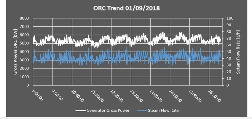
Clean technologies in steelmaking
Auxiliary condenser                                                 of heating the make-up water, removing the dissolved gases
The purpose of the auxiliary condenser is to condense any           (carbon dioxide and oxygen) and preventing metallic corrosion.
excess steam into the system in order to prevent pressure rises     The feed pump unit has 3 centrifugal pumps driven by electric
beyond the expected limits.                                         motors with frequency inverter; they take the water from the
Thanks to the auxiliary condenser the steam cools down and          feed tank and transfer it to the waste heat boiler.
changes into condensate up to 90 °C; condensate is recovered
at the outlet and sent to the feed water tank.                      THE ORC SYSTEM
                                                                    ORC overview
Feed water unit                                                     The ORC is a Rankine Cycle using an organic heavy molecular
The feed water unit is composed of a degasser and a feed wa-        weight fluid instead of water and steam to convert heat to
ter pump unit.                                                      power.
The degasser is a horizontal cylindrical tank the purpose of        The organic fluid allows to have a self-controlled, easy-to-run
which is to eliminate the gases dissolved in the water, to store    power system without superheating. This is due to the proper-
the water at a fixed temperature (105 °C) before sending it         ties (saturation curve) of organic fluids, ensuring dry expansion
to the boiler and to collect the condensate coming back from        in a turbine even without superheating. The scheme of the ORC
users and automatic drains.                                         and saturation curves of typical organic fluids are shown below
At the top of the degasser a deaerator is installed with the aim    (Fig.5).

Fig. 5 – Saturation curves of some organic fluids and Rankine cycle (1).

The liquid organic fluid is pressurized by the pump (1 to 2),       and of course in energy recovery from industrial processes (i.e.
preheated in a regenerator (2 to 3), further heated and vapori-     cement, glass, metals). All units have the same overall confi-
zed in the evaporator (3 to 4); the vapor expands in the turbine    guration and although different in size share the conceptual
generating power, is cooled in the regenerator (5 to 6), finally    design of the turbine and of other main components.
returning to the liquid phase in the condenser.                     The turbine is a high efficiency multistage axial flow machine,
The ORC has become the preferred option instead of the tradi-       with integral casing and overhang shaft and rotor resting on
tional water and steam turbine Rankine Cycle at temperatures        roller bearings. It has mechanical seals and rotates at mode-
below 350 °C and/or in small thermal power systems with no          rate speed (typically 3,000 rpm), allowing in most cases direct
dedicated operator.                                                 coupling with a 2-pole induction generator. When a typical-
This is the case of EAF heat recovery systems where an inter-       ly 4-pole synchronous generator is used, especially in larger
mediate heat carrier loop (saturated steam) is used to capture,     ORCs, a gear reducer is usually employed.
buffer and convey the heat recovered from the off-gas (discon-      The turbine is designed to allow access to the mechanical seals
tinuous and highly variable).                                       and bearings for inspection and possible replacement without
Heat recovery ORCs                                                  emptying the organic fluid from the casing. This is done remo-
Over 300 ORCs supplied by Turboden, with unit capacity betwe-       ving first the coupling between the turbine and the generator
en 200 kW and 15 MW, are used mostly in renewables (bio-            (or the gear reducer).
mass and geothermal) but also in converting residual heat from      The feed pump, used to control the ORC turbine power output,
engines or gas turbines (small combined cycle power plants)         is run by variable frequency drive to adjust the flow of the or-

24                                                                                                La Metallurgia Italiana - n. 5 2019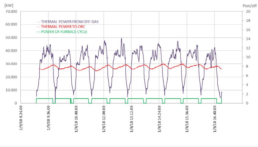
Tecnologie pulite per la produzione d’acciaio
ganic fluid depending on the low temperature heat rejected by      considering that the guaranteed gross power output at the ge-
the ORC at the condenser.                                          nerator terminals is about 7 MW when the nominal thermal
Other ORC features vary depending on the type and the tempe-       power of steam entering the ORC is 34.300 kW (Tab. 5).
rature of the heat source and of the heat sink (condenser) and     In fact the generator rating corresponds to the maximum po-
on other site conditions. The heat source can be for instance      wer output of the turbine required and agreed with Arvedi at
geothermal water at moderate temperature, higher temperatu-        the beginning of the project. This extra capacity of the ORC and
re thermal oil typically used as heat carrier from biomass com-    turbine allows advantage to be taken of some additional ste-
bustion furnaces, condensing vapor or hot air directly. The heat   am thermal power coming from the iRecovery® system, but is
sink is often a closed loop cooling water system. The cooling      meant also allows the possibility of utilizing in the future other
water temperature is as low as possible to maximize power,         non-identified heat streams made available within the Arvedi
or at higher level, in CHP applications when there is a heat       plant in Cremona. In fact, the Arvedi ORC can deliver up to 10
user (e.g. district heating). Air Cooled Condensers are used       MW gross power at the generator terminals with a thermal
now more and more especially in large ORCs when space is           input of about 46,000 kW.
available.                                                         The portion of thermal energy that is not converted to mecha-
The temperature range between heat source and heat sink and        nical/electrical energy, aside from the thermal losses of the
the ORC size typically determine the most appropriate type of      equipment, is transferred to the low temperature heat carrier
working fluid among siloxanes, hydrocarbons or refrigerants        (heat sink). At Arvedi the heat sink is a water-cooled condenser,
and the number of stages of the high efficiency axial turbine.     with water circulated in cooling towers. This was preferred to
Heat transfer and heat exchangers play an important role in        Air Cooled Condenser due to space limitations and the oppor-
ORC. Since the Carnot efficiency is inevitably low in case of      tunity to connect to the existing cooling water lines.
moderatetemperature heat sources typical of ORC applications,      In the closed loop ORC system, the organic working fluid is
the many heat exchangers used in ORCs must work with very          preheated, evaporated and slightly superheated in four “hot”
low Delta T and pinch points to approach as much as possible       heat exchangers (split system, regenerator, preheater and eva-
the Carnot efficiency.                                             porator). The resulting organic vapor spins the turbine driving
The ORC overall dimension varies greatly with size: from a 300     the generator while expanding, then still as hot vapor, it goes
kW water cooled condenser ORC fitting in a standard 40 ft          to the regenerator to heat up the cold still liquid organic fluid
container to a 15 MW air cooled condenser ORC covering an          (internal heat transfer to increase efficiency).The organic vapor
area of 8,000 square meter.                                        is then cooled and condenses releasing heat into the water-co-
                                                                   oled condenser. After the condenser, the organic liquid is pum-
Heat recovery ORCs                                                 ped to the pressure level required for turbine operation, then
The ORC turbogenerator converts thermal energy to electricity      divided into two streams with the largest portion of the flow
with the turbine coupled to an electric generator.                 going to the internal regenerator for preheating and a small
The Arvedi ORC is equipped with a 12 kVA, 4-pole, and 1,500        fraction going through the “split system” to capture the low
rpm synchronous generator. A gear reducer is therefore interpo-    temperature heat of the condensate. The flow sheet is shown
sed for coupling to the 3,000 rpm turbine (Fig.8).                 below (Fig. 6).
The 12 kVA rating of the generator might appear oversized

Fig. 6 – Arvedi ORC Simplified flow sheet.

La Metallurgia Italiana - n. 5 2019                                                                                               25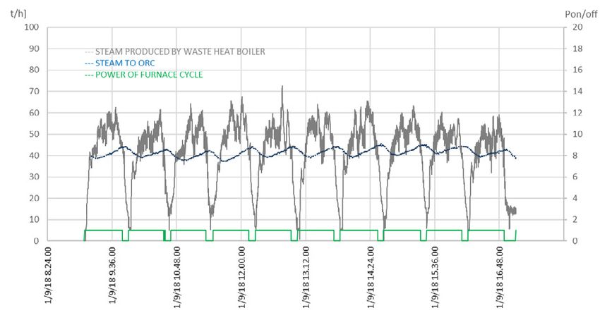
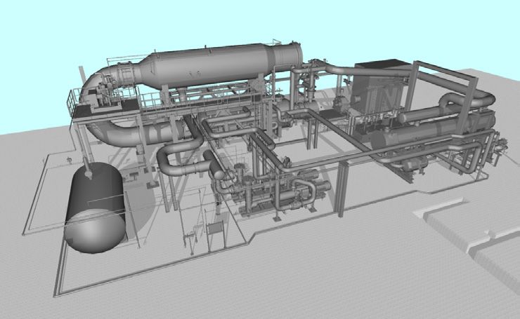
Clean technologies in steelmaking

Fig. 7 – Arvedi ORC 3D rendering.

Fig. 8 – ORC Turbine, reducer and generator.

Arvedi ORC design and performance data
The design and performance data of the Arvedi ORC are summarized in the following table (Tab.3).

26                                                                                           La Metallurgia Italiana - n. 5 2019
Tecnologie pulite per la produzione d’acciaio

Tab. 3 – ORC design and performance data.

                                          ORC DESIGN & PERFORMANCE DATA
                                              Winter                           Medium                         Summer
   High temperature heat Winter                                          Dry Saturated Steam
   Steam pressure at ORC inlet                                                 16 bar g
  Steam temperature at ORC inlet                                                204 °C
   Steam flow rate at ORC inlet                                                51.8 t/h
    Thermal power at ORC inlet                                                34,300 kW
   Low temperature heat carrier
                                                                                Water
       (condenser cooling)
           Working fluid                                                    Cyclopentane
              Turbine                                                   Axial flow multi stage
         Electric generator                                   4 pole, synchronous, 3-phase, 50 Hz, 6000 V
    ORC gross power output (at
                                             7,237 kW                         6,995 kW                       6,673 kW
   electrical generator terminals)
   ORC own power consumption                 312 kW                            324 kW                         329 kW
    ORC guaranteed net power
                                             6,925 kW                         6,671 kW                       6,344 kW
             output

The table has three columns (winter, medium, summer) to show        INITIAL OPERATION RESULTS
how the typical ambient conditions in the different seasons af-     Since February 8, 2018 the heat recovery system has been run-
fect the temperature of the cooling water available at the con-     ning as continuously as possible following the actual operation
denser. The temperature of the water from the cooling towers        schedule of the ESP line and the 250-t Consteel® steelmaking
depends on the ambient temperature and relative humidity.           EAF.
The average output of the ORC is somewhat lower in summer           Actual data from operation demonstrate that the overall heat
than in winter and in hot humid days compared to cooler and         recovery system is capable of working according to design and
maybe drier nights.                                                 reaching and exceeding the agreed performance. The ORC in
                                                                    particular has recorded 7.9 MW gross power output, well abo-
PROJECT SCHEDULE AND COMMISSIONING                                  ve nominal values (Tab. 4).
In December 2015 Arvedi accepted the proposals submitted by         The actual performance of the iRecovery® system and of the
Tenova for the iRecovery® system and by Turboden for the ORC        ORC unit during a typical sequence of heats allows one to ap-
unit and agreed with them the scope of work, performance            preciate how effectively energy is recovered from the off-gas,
and main technical and economic aspects of the heat recovery        transferred as thermal energy to the ORC after smoothing with
project. The corresponding contracts were signed in December        the steam accumulator and then converted to mechanical/elec-
2015 and at the beginning of January 2016.                          trical energy.
After a slow-down of the whole schedule, the erection activities    The first chart shows a comparison between the trend of fumes
were completed in December 2017 before the scheduled win-           thermal power and the trend of steam power; the second one
ter shutdown of the ESP steelmaking line.                           shows a comparison between the trend of steam production
The first ORC parallel to the grid occurred on January 23, 2018,    from a waste heat boiler and the trend of steam delivery to the
but in fact actual operation of the ORC started a couple of         ORC hot module.
weeks later after adjustments to the iRecovery® system that         Finally, the third chart shows the steam flow input and cor-
allowed a more continuous flow of steam to the ORC to be            responding gross power output of the ORC for the same 10
achieved.                                                           consecutive heats on September 1, 2018.

La Metallurgia Italiana - n. 5 2019                                                                                             27
Clean technologies in steelmaking Fig. 9 – Thermal power during 10 consecutive EAF working cycles. Fig.10 – Steam production during 10 consecutive EAF working cycles. 28 La Metallurgia Italiana - n. 5 2019
Tecnologie pulite per la produzione d’acciaio

Fig. 11 – ORC gross power during 10 consecutive EAF working cycles.

These charts also show that the thermal power captured from       The overall performance of the initial operation is shown below,
the off-gas and sent to the ORC (about 27 MW) is lower than       reporting data from the ORC supervision system with reference
nominal (34 MW). This affects the ORC gross power output          to the time interval between February 9, 2018 and September
typically below 6 MW.                                             17, 2018 (date of writing this paper).
The lower thermal power available during initial operation        Please note that this period also includes a scheduled one-
is due to the pre-existing off-gas collection system requiring    month long summer shutdown of the complete ESP line and
some adjustments to ensure that all the Consteel® EAF off-        steelmaking EAF.
gas stream reaches the waste heat boiler (no leakage to the       The steam flow input and the generator power output recor-
quench tower) and to inhibit the entrance of false air.           dings for the same time interval are shown in the chart (Fig.12).
These modifications, scheduled to be carried out as soon as       The graph allows one to appreciate the profile of the thermal
possible, will increase the steam flow-rate and ensure the ORC    power input to the ORC, the resulting variation of the generator
gross power output reaches and exceeds 7 MW.                      output and the frequent interruptions of the steam flow.

Fig. 12 – Steam flow (red line) and ORC generator power output (blue line).

La Metallurgia Italiana - n. 5 2019                                                                                             29
Clean technologies in steelmaking
The summary of the ORC performance during the same time interval is shown in the following table (Tab.4).

Tab. 4 – ORC Initial operation performance (Feb 9, 2018 – Sep 17, 2018).

                     ORC INITIAL OPERATION PERFORMANCE (FEB 9, 2018 – SEP 17, 2018)
                                   ORC running hours                                                3,287                     h
                  Peak Power (one hour average at generator terminals)                              7,929                    kW
                                  Average steam flow                                                 28.5                    t/h
                                  Average gross Power                                               4,495                    kW
                             Total energy produced (gross)                                        14,776,091                kW/h

The ORC gross peak power value at 7.9 MW demonstrates the                vative solutions, should help other steelmakers to develop and
system capability exceeding the nominal design.                          support other inventive technologies capable of reducing the
The average steam flow (28.5 t/h) is lower than nominal (51.8            steel industry’s reliance on fossil fuels.
t/h) due to the mentioned issues in the pre-existing off-gas             More European steelmakers would likely be willing to invest
collection system. Initial adjustments made during the summer            in new technologies to reduce their emissions in line with the
shut-down allowed the average steam flow between Aug 18                  EU Climate Action targets after the Paris Agreement if finan-
and Sep 17 to be raised to 35.5 t/h.                                     cial support policies were available to reduce the capital cost
The joint work in progress between Arvedi, Tenova and Turbo-             of new emission reduction equipment. If they could count on
den personnel is focused on reducing the frequent interrup-              more incentives for energy efficiency projects, EAF mini-mills
tions and completing the agreed modifications to the off-gas             could strengthen their role as lower carbon steelmakers com-
collection during the next major scheduled steel shop main-              pared to BF-BOF plants.
tenance shut down. These actions will ensure a more stable
continuous operation and higher power output.                            ACKNOWLEDGEMENT
                                                                         The authors dedicate this work to the memory of Jean Vallomy,
CONCLUSIONS                                                              a strong willed person and a true technology innovator in EAF
The initial operation results at the Arvedi Cremona ESP ste-             steelmaking, who passed away last October 3rd, 2018, aged
elmaking line confirm that off-gas heat recovery and its va-             90. Jean Vallomy worked in steel-plants for over 70 years, star-
lorization with ORC is a practical way to improve the energy             ting in his native Val d’Aosta, then in other melt shops in Italy,
efficiency of large high-performance EAFs.                               Mexico, Argentina and Venezuela. In his fifties he moved to
Eight iRecovery® systems using EAF residual heat and four                the United States, later becoming a citizen, where he set up in
ORCs converting steam to power at major electric steelmaking             Charlotte North Carolina, his own technology company and de-
plants in Europe and in the Far East demonstrate that two well-          veloped the innovative Consteel scrap charging and preheating
proven technologies are available to steelmakers to render their         system and other EAF technology innovations (4).
operations more sustainable while reducing operating costs.              In one of his last trips to Italy, Jean Vallomy came to Cremona
The example of entrepreneurs like Arvedi who undertake inno-             in 2011 to visit the Consteel EAF and pay tribute to Mr. Arvedi.

REFERENCES

[1]    Schliephake, Born, Granderath, Memoli, Simmons, Heat Recovery for the EAF of Georgsmarienhütte, AISTech 2010 proceedings,
       Volume 1.
[2]    T. Bause, F. Campana, L. Filippini, A. Foresti, N. Monti, T. Pelz, Cogeneration with ORC at Elbe-Stahlwerke Feralpi EAF Shop, Iron
       & Steel Technology Magazine, May 2015.
[3]    N. Monti, C. Giavani, U. De Miranda, N. Gaudenzi, A New Consteel® With iRecovery®: Better Performances in Steel Production
       With Heat Recovery for District Heating and ORC Turbine Power Generation, Proceedings AISTech, May 2015.
[4]    F. Memoli, A. Manenti, A New Era for the Continuous Scrap Charge: the Definitive Success of Consteel® Technology and Its Ex-
       pansion in Europe From a Productivity and Environmental Perspective, IAS Steelmaking Conference, Rosario, November 2007.

30                                                                                                     La Metallurgia Italiana - n. 5 2019
You can also read