MFC Sinewave Filter Kit Installation Instructions - TCI, LLC
←
→
Page content transcription
If your browser does not render page correctly, please read the page content below
MFC Sinewave Filter Kit
Installation Instructions

                TCI, LLC
                W132 N10611 Grant Drive
                Germantown, Wisconsin 53022

                Phone: 414-357-4480
                Fax: 414-357-4484
                Helpline: 800-TCI-8282
                Web Site: http://www.transcoil.com
                © 2019 TCI, LLC All rights reserved
                Effective: 01/09/2020 Version: E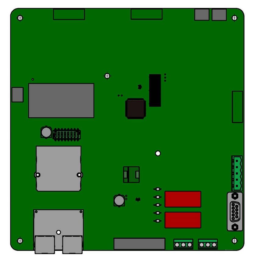
Revision                        Description                               Date
    A                               Release                           09/27/2016
    B                Update to drawings, heat loss                    08/07/2018
    C               Update to drawings and cooling                    12/13/2018
                    Various text updates; added
    D           Maintenance and Service section and                   04/09/2019
                         PQconnect option
    E                Updates to PQconnect section                     01/09/2020

 No part of this publication may be reproduced, stored in a retrieval system, or transmitted in
 any form or by any means, mechanical, electronic, photocopying, recording, or otherwise,
 without the prior written permission of TCI, LLC. The information in this manual is subject to
 change without notice. Every precaution has been taken in the preparation of this manual.
 TCI, LLC assumes no responsibility for errors or omissions. Neither is any liability assumed
 for damages resulting from the use of the information contained in this publication.
Table of Contents
 Introduction ............................................................................................................................................................ 2
              Safety Instructions Overview ............................................................................................................. 2
              Warnings and Cautions ..................................................................................................................... 2
              General Safety Instructions ............................................................................................................... 3

 Receiving Inspection and Storage ....................................................................................................................... 4
             Receiving Inspection ......................................................................................................................... 4
             Storage Instructions .......................................................................................................................... 4
             TCI Limited Warranty Policy .............................................................................................................. 4

 Pre-Installation Planning ...................................................................................................................................... 6
               Intended Audience ............................................................................................................................ 6
               Verify the Application......................................................................................................................... 6
               Variable Frequency Drive Settings .................................................................................................. 10
               Select a Suitable Location ............................................................................................................... 11
               Mounting the Filter Kit ..................................................................................................................... 11
               Power Wiring ................................................................................................................................... 11
               Filter Schematic ............................................................................................................................... 11
               Line Reactor Wiring ......................................................................................................................... 13
               Capacitors ....................................................................................................................................... 14
               Capacitor Brackets .......................................................................................................................... 15
               Recommendations for MFC Kit Usage............................................................................................ 16
               Wire Sizing ...................................................................................................................................... 16
               Installation Guidelines ..................................................................................................................... 21

 PQconnect Connectivity Option ........................................................................................................................22
           Product Description ......................................................................................................................... 22
           Modbus RTU Connections .............................................................................................................. 23
           Register Map ................................................................................................................................... 24
           PQconnect Hardware ...................................................................................................................... 32
           PCB Connections ............................................................................................................................ 35
           Troubleshooting............................................................................................................................... 37

 Maintenance and Service ...................................................................................................................................40

 Periodic Maintenance..........................................................................................................................................40

 Troubleshooting ..................................................................................................................................................40

 Evaluating MFC Sinewave Filter Performance .................................................................................................41

 Replacement Parts ..............................................................................................................................................41

 Factory Contacts and Tech Support .................................................................................................................41

 Product Description .............................................................................................................................................. 6
            Part Number Encoding ...................................................................................................................... 7
            MFC “A” Filter Kit – Sinewave Filter Kit with damping resistor ......................................................... 8
            MFC “A” Filter Kit Part Number and Ratings ..................................................................................... 9
            MFC “R” Filter Kit – Sinewave Filter Kit without damping resistor .................................................... 9
            MFC “R” Filter Kit Part Number and Ratings................................................................................... 10

                                                                                   1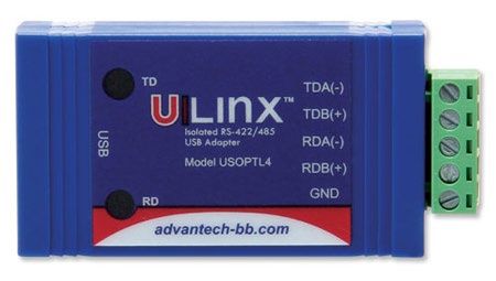
MFC Kit IOM                                                                                   1.0 Introduction

  1.0         Introduction
     The information presented in this manual covers the MFC Sinewave Filter Kit
     (MFC Filter kit) only.

     Safety Instructions Overview
              This section provides the safety instructions which must be followed when installing, operating, and
              servicing the MFC Filter Kit. If neglected, physical injury or death may follow, or damage may occur
              to the filter or equipment connected to the filter. The material in this chapter must be read and
              understood before attempting any work on, or with, the product.

              The MFC Filter Kit is intended to be connected to the output terminals of a variable frequency drive
              (VFD). An AC motor is connected to the output terminals of the MFC Kit and receives power from
              the VFD through the MFC Filter Kit. The instructions, and particularly the safety instructions, for the
              VFD, motor and any other related equipment must be read, understood and followed when working
              on any of the equipment.

     Warnings and Cautions
              This manual provides two types of safety instructions. Warnings are used to call attention to
              instructions that describe steps that must be taken to avoid conditions that can lead to a serious
              fault condition, physical injury, or death.

              Cautions are used to call attention to instructions that describe steps that must be taken to avoid
              conditions that can lead to a malfunction and possible equipment damage.

              Warnings
              Readers are informed of situations that can result in serious physical injury and/or serious damage
              to equipment with warning statements highlighted by the following symbols:

                       Warning         Dangerous Voltage Warning: warns of situations where
                                       high voltage can cause physical injury and/or damage
                                       equipment. The text next to this symbol describes ways
                                       to avoid the danger.
                       Warning         General Warning: warns of situations that can cause
                                       physical injury and/or damage equipment by means
                           !           other than electrical. The text next to this symbol
                                       describes ways to avoid the danger.
                       Warning         Electrostatic Discharge Warning: warns of situations in
                                       which an electrostatic discharge can damage
                                       equipment. The text next to this symbol describes ways
                                       to avoid the danger.

              Cautions
              Readers are informed of situations that can lead to a malfunction and possible equipment damage
              with caution statements:

                       Caution         General Caution: identifies situations that can lead to a

                           !
                                       malfunction and possible equipment damage. The text
                                       describes ways to avoid the situation.

                                                        2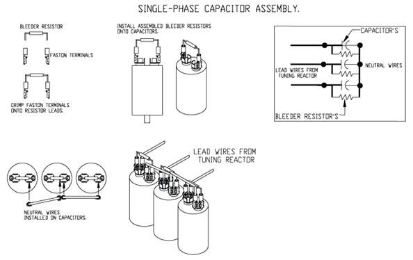
MFC Kit IOM                                                                                   1.0 Introduction

     General Safety Instructions
              These safety instructions are intended for all work on the MFC Filter Kit. Additional safety
              instructions are provided at appropriate points on other sections of this manual.

                 Warning
                                Be sure to read, understand, and follow all safety

                      !         instructions.

                 Warning
                                Only qualified electricians should carry out all electrical

                      !         installation and maintenance work on the MFC Filter Kit.

                 Warning        All wiring must be in accordance with the National
                                Electrical Code (NEC) and/or any other codes that apply
                      !         to the installation site.

                 Warning
                                Disconnect all power before working on the equipment.
                                Do not attempt any work on a powered MFC Filter Kit.

                 Warning
                                The MFC Filter Kit, drive, motor, and other connected
                                equipment must be properly grounded.

                                After switching off the power, always allow 5 minutes for
                                the capacitors in the MFC Filter Kit and in the drive to
                 Warning        discharge before working on the MFC Kit, the drive, the
                                motor, or the connecting wiring. It is a good practice to
                                check with a voltmeter to make sure that all sources of
                                power have been disconnected and that all capacitors
                                have discharged before beginning work.

                                                     3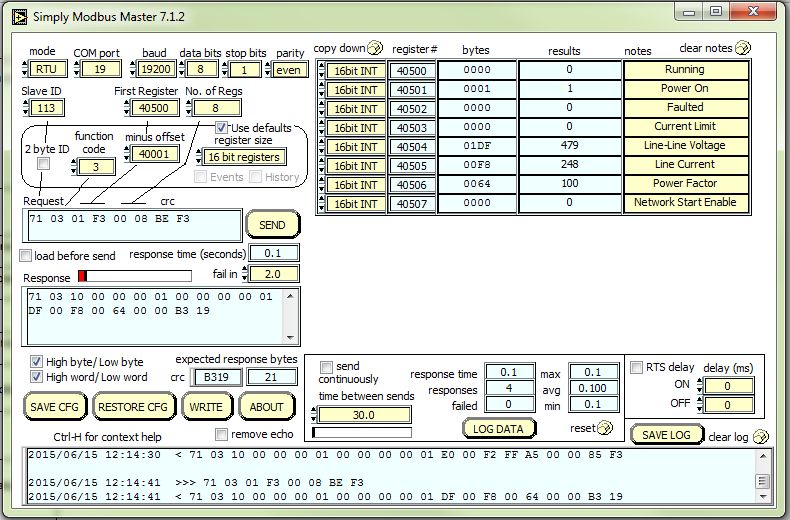
MFC Kit Instructions                                            2.0 Receiving Inspection and Storage

   2.0      Receiving Inspection and Storage
            Thank you for selecting the MFC Filter Kit. TCI has produced this filter for use in many variable
            frequency drive (VFD) applications that require output voltage filtering. This manual gives an
            overview of how to install, operate and maintain the MFC Filter Kit. Please contact TCI Technical
            Support or visit https://transcoil.com/Support for additional information

      Receiving Inspection
            The MFC Filter Kit has been thoroughly inspected at the factory and carefully packaged for
            shipment. When you receive the unit, you should immediately inspect the shipping container and
            report any damage to the carrier that delivered the unit. Verify that the part number of the
            components you received is the same as the part numbers listed on the engineering drawings for
            the kit which can be found at:

            https://transcoil.com/products-kmg-mfcdrawings-htm/

      Storage Instructions
            If the MFC Filter Kit is to be stored before use, be sure that it is stored in a location that conforms
            to published storage humidity and temperature specifications in this manual and on the applicable
            technical drawings available at: transcoil.com. Store the unit in its original packaging.

      TCI Limited Warranty Policy
            TCI, LLC (“TCI”) warrants to the original purchaser only that its products will be free from defects
            in materials and workmanship under normal use and service for a period originating on the date of
            shipment from TCI and expiring at the end of the period described below:
                  Product Family                          Warranty Period
                                        For the life of the drive with which they are
                    KLR, KDR
                                        installed.

                                        One (1) year of useful service,
                 HGA, V1K, KLC          not to exceed 18 months from the date of
                                        shipment.

              MFC, HG7, KH, KRF         Three (3) years from the date of shipment.

                   KCAP, KTR            Five (5) years from the date of shipment.

                                        One (1) year of useful service,
                All Other Products      not to exceed 18 months from the date of
                                        shipment.

            The foregoing limited warranty is TCI’s sole warranty with respect to its products and TCI makes
            no other warranty, representation, or promise as to the quality or performance of TCI’s products.
            THIS EXPRESS LIMITED WARRANTY IS GIVEN IN LIEU OF AND EXCLUDES ANY AND ALL
            EXPRESS OR IMPLIED WARRANTIES INCLUDING, WITHOUT LIMITATION, ANY IMPLIED
            WARRANTY OF MERCHANTABILITY OR FITNESS FOR A PARTICULAR PURPOSE.
            This warranty shall not apply if the product was:
                a) Altered or repaired by anyone other than TCI;
                b) Applied or used for situations other than those originally specified; or
                c) Subjected to negligence, accident, or damage by circumstances beyond TCI’s control,
                   including but not limited to, improper storage, installation, operation, or maintenance.

                                                      4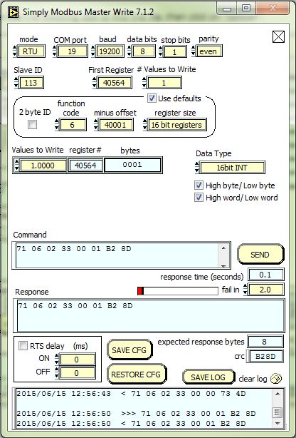
MFC Kit Instructions                                           2.0 Receiving Inspection and Storage

            If, within the warranty period, any product shall be found in TCI’s reasonable judgment to be
            defective, TCI’s liability and the Buyer’s exclusive remedy under this warranty is expressly limited,
            at TCI’s option, to (i) repair or replacement of that product, or (ii) return of the product and refund
            of the purchase price. Such remedy shall be Buyer’s sole and exclusive remedy. TCI SHALL NOT,
            IN ANY EVENT, BE LIABLE FOR INCIDENTAL DAMAGES OR FOR CONSEQUENTIAL
            DAMAGES INCLUDING, BUT NOT LIMITED TO, LOSS OF INCOME, LOSS OF TIME, LOST
            SALES, INJURY TO PERSONAL PROPERTY, LIABILITY BUYER INCURS WITH RESPECT TO
            ANY OTHER PERSON, LOSS OF USE OF THE PRODUCT OR FOR ANY OTHER TYPE OR
            FORM OF CONSEQUENTIAL DAMAGE OR ECONOMIC LOSS.
            The foregoing warranties do not cover reimbursement for removal, transportation, reinstallation, or
            any other expenses that may be incurred in connection with the repair or replacement of the TCI
            product.
            The employees and sales agents of TCI are not authorized to make additional warranties about
            TCI’s products. TCI’s employees and sales agent’s oral statements do not constitute warranties;
            these shall not be relied upon by the Buyer and are not part of any contract for sale. All warranties
            of TCI embodied in this writing and no other warranties are given beyond those set forth herein.
            TCI will not accept the return of any product without its prior written approval. Please consult TCI
            Customer Service for instructions on the Return Authorization Procedure.

                                                      5
MFC Kit Instructions 3.0 Pre-Installation Planning
3.0 Pre-Installation Planning
Intended Audience
This manual is intended for use by all personnel responsible for the assembly, wiring installation,
operation and maintenance of the MFC Filter Kit. Such personnel are expected to have knowledge of
electrical wiring practices, electronic components and electrical schematic symbols. Panel design using
a TCI MFC Filter Kit should be performed with appropriate engineering supervision so the design meets
the requirements based on materials utilized in the construction of the panel, wiring practices followed
by your shop, and the actual ambient conditions of the components for each application.
Product Description
The MFC Filter kit is a low-pass sine wave filter designed and developed by TCI to deliver
conditioned power to motor loads driven by PWM drives at a variety of lead lengths. The MFC Kit
is available for 460/480 Volt and 575/600 Volt systems.
The MFC Filter kit is a passive filter connected in series with the output terminals of the variable
frequency drive. It is designed to remove the carrier frequency distortion from the output voltage
waveform. The use of this low-pass filter will result in a nearly pure sine wave voltage profile. This
design will reduce the effects of the reflected wave phenomenon, (dV/dt), such as insulation
damage or premature failure in motors, transformers, and VFD output cables. The MFC Filter Kit
will also reduce the effects of stray high frequency harmonic currents, thereby reducing VFD ground
fault problems and noise interference in transducer signals.
The MFC Filter Kit is suitable for all lead lengths extending as far as 15,000 feet.
The MFC Filter Kit is available in the following configurations:
1. MFC A - Sinewave Filter Kit with damping resistor
2. MFC R - Sinewave Filter Kit without damping resistor
The MFC Filter Kit consists of the following standard features and components:
• A TCI 3-phase line reactor specifically designed for high PWM ripple current from the
sinewave filter application
• High-endurance, PWM current ripple rated capacitors
• Damping resistors (optional)
• Capacitor bleeder resistors to ensure safe capacitor discharge upon filter shutdown.
• Brackets for mounting capacitors to a panel
6MFC Kit Instructions 3.0 Pre-Installation Planning
Table 23 – MFC Sinewave Filter Technical Specifications
Voltage Rating 460/480 V and 575/600 V, 3-phase
Fundamental Frequency Range 0 Hz to 80 Hz Max.
Horsepower Ratings 5 HP – 1000 HP at 480 V
5 HP – 750 HP at 600 V
Consult Factory for additional ratings
See Rating table for current ratings
Overload Capability 150% of rated current for 1 minute every 60 minutes:
VFD carrier frequency 2 kHz to 16 kHz, greater than 4 kHz preferred
Maximum output 480 V models: 600 V models:
Peak Voltage: 1000 V 1500 V
Peak dV/dt: 500 V/μs 1500 V/μs
Insertion impedance Approximately 6.5% at 60 Hz & rated current
Capacitors Oil filled or dry high endurance design (no PCBs)
Environmental Conditions
Operating Temperature Kit component ambient: 50°C (122°F)
Storage Temperature 60°C (140°F)
Elevation Up to 2,000 m without derating
Humidity 95% non-condensing
Agency approvals or certifications
Capacitors UR and cUR Recognized
Reactors UR and cUR Recognized
Part Number Encoding
Figure 12 identifies the significance of each character in the MFC part number. The example part
number MFC130AR designates an MFC kit that is rated 130A, 480 Volts and does not include
resistors.
Figure 12: MFC Kit Part Number Encoding
NOTE: Individual part drawings for each component included in the MFC Filter Kits are found at:
https://transcoil.com/products-kmg-mfcdrawings-htm/
7MFC Kit Instructions 3.0 Pre-Installation Planning
MFC “A” Filter Kit – Sinewave Filter Kit with damping resistor
The MFC Filter Kit is a harmonic filter component package designed and developed by TCI to allow
qualified customers to build sinewave filters to for the output of VFDs. The filter components are
designed to filter out PWM switching ripple when applied correctly and following the schematic
connections used by TCI. The MFC Filter Kit is available for 480 Volt and 600 Volt systems. When
properly designed, assembled, and installed, the completed product is intended to be suitable for use
with 3-phase PWM AC VFDs. The MFC A Filter Kit component package consists of the following
components:
• A KTRMG series filter reactor.
o The 480 V/900 HP and larger units include two reactors that need to be wired in
parallel.
• High-endurance, PWM ripple current rated capacitors.
o Bleeder resistors to ensure safe capacitor discharge on filter shutdown, located on
capacitors.
• Damping resistors
o High power 3-phase damping resistors to reduce BFD control or load dynamic
induced resonances. Damping resistors are recommended for applications which
have dynamically changing loads like hoists, elevators, or servos.
• Capacitor mounting brackets
o Capacitor mounting brackets are provided on 50 HP and higher rated kits
o Kits from 5 through 40 HP are not provided with capacitor brackets because
these units utilize single phase capacitors that do not have mounting brackets
available for them. These small size single phase capacitors are typically
mounted vertically due to the small size and reduced use of panel space.
8MFC Kit Instructions 3.0 Pre-Installation Planning
MFC “A” Filter Kit Part Number and Ratings
HP Amp 480 Volt Model HP Amp 575/600 Volt Model
5 8 MFC008AA 5 8 MFC008CA
7.5 12 MFC012AA
7.5 10 MFC010CA
10 16 MFC016AA
15 23 MFC023AA 10 12 MFC012CA
20 30 MFC030AA 15 20 MFC020CA
25 35 MFC035AA 20 25 MFC025CA
30 45 MFC045AA
575/600 Volt MFC Kit
25 28 MFC028CA
40 55 MFC055AA 30 35 MFC035CA
50 65 MFC065AA
480 Volt MFC Kit
40 45 MFC045CA
60 80 MFC080AA
50 55 MFC055CA
75 110 MFC110AA
100 130 MFC130AA 60 65 MFC065CA
125 160 MFC160AA 75 80 MFC080CA
150 200 MFC200AA 100 110 MFC110CA
200 250 MFC250AA 125 130 MFC130CA
250 305 MFC305AA 150 160 MFC160CA
300 362 MFC362AA 200 200 MFC200CA
350 420 MFC420AA 250 250 MFC250CA
400 480 MFC480AA 300 305 MFC305CA
450 540 MFC540AA 350 362 MFC362CA
500 600 MFC600AA 400 420 MFC420CA
600 750 MFC750AA 450 450 MFC450CA
700 850 MFC850AA 500 500 MFC500CA
800 960 MFC960AA 600 600 MFC600CA
900 1080 MFC1080AA 750 750 MFC750CA
1000 1200 MFC1200AA
MFC “R” Filter Kit – Sinewave Filter Kit without damping resistor
The MFC Filter Kit is a harmonic filter component package designed and developed by TCI to allow
qualified customers to build sinewave filters to for the output of VFDs. The filter components are
designed to filter out PWM switching ripple when applied correctly and following the schematic
connections used by TCI. The MFC Filter Kit is available for 480 Volt and 600 Volt systems. When
properly designed, assembled, and installed, the completed product is intended to be suitable for use
with 3-phase PWM AC VFDs.
The MFC “R” Filter Kit component package consists of the following components:
• A KTRMG series filter reactor.
o The 480 V/900 HP and larger units include two reactors that need to be wired in
parallel.
• High-endurance, PWM ripple current rated capacitors.
o Bleeder resistors to ensure safe capacitor discharge on filter shutdown, located on
capacitors.
• Capacitor mounting brackets
o Capacitor mounting brackets are provided on 50 HP and higher rated kits
o Kits from 5 through 40 HP are not provided with capacitor brackets because these
units utilize single phase capacitors that do not have mounting brackets available for
them. These small size single phase capacitorss are typically mounted vertically due
to the small size and reduced use of panel space.
9MFC Kit Instructions 3.0 Pre-Installation Planning
• Note: There are no damping resistors included, these kits are most suitable for VFD
applications with low load and VFD dynamics
MFC “R” Filter Kit Part Number and Ratings
HP Amp 480 Volt Model HP Amp 575/600 Volt Model
5 8 MFC008AR 5 8 MFC008CR
7.5 12 MFC012AR 7.5 10 MFC010CR
10 16 MFC016AR 10 12 MFC012CR
15 23 MFC023AR 15 20 MFC020CR
20 30 MFC030AR
20 25 MFC025CR
25 35 MFC035AR
25 28 MFC028CR
575/600 Volt MFC Kit
30 45 MFC045AR
30 35 MFC035CR
40 55 MFC055AR
480 Volt MFC Kit
40 45 MFC045CR
50 65 MFC065AR
60 80 MFC080AR 50 55 MFC055CR
75 110 MFC110AR 60 65 MFC065CR
100 130 MFC130AR 75 80 MFC080CR
125 160 MFC160AR 100 110 MFC110CR
150 200 MFC200AR 125 130 MFC130CR
200 250 MFC250AR 150 160 MFC160CR
250 305 MFC305AR
200 200 MFC200CR
300 362 MFC362AR
350 420 MFC420AR 250 250 MFC250CR
400 480 MFC480AR 300 305 MFC305CR
450 540 MFC540AR 350 362 MFC362CR
500 600 MFC600AR 400 420 MFC420CR
600 750 MFC750AR 450 450 MFC450CR
700 850 MFC850AR 500 500 MFC500CR
800 960 MFC960AR
600 600 MFC600CR
900 1080 MFC1080AR
750 750 MFC750CR
1000 1200 MFC1200AR
Verify the Application
MFC Filter Kit Rating
Make sure that the MFC Filter Kit is correct for the application. The voltage rating of the filter kit
must match the voltage and current rating of the connected drive. The horsepower and current
rating of the filter kit must be appropriate for the connected load.
Variable Frequency Drive Settings
Make sure that the variable frequency drive will be set for operation modes and ranges that are
compatible with the MFC Kit:
• Maximum output frequency: 80 Hz
• Constant PWM switching (carrier) frequency between 2 kHz and 12 kHz, ideally 4
kHz to 8 kHz
• Mode of operation: speed control "scalar" or "V/Hz" without DC braking unless the drive
application has been confirmed by TCI Technical Support
• Consult VFD manual for other drive specific recommendations for use with sinewave
filters, specific instructions may include but are not limited to: disabling any variable PWM
switching frequency options such as features to reduce motor noise or control
temperature and setting drive to continuous 3-phase modulation. Six-step operation is not
compatible with sinewave filter technology.
10MFC Kit Instructions 3.0 Pre-Installation Planning
Select a Suitable Location
Environment
Locating the MFC Filter in a suitable environment will help ensure proper performance and a normal
operating life. Refer to the environmental specifications listed on Table 5.
Warning Unless specifically labeled as approved for such use, this equipment
is not suitable for use in an explosive atmosphere or in a "Hazardous
! (Classified) Location" as defined in article 500 of the National
Electrical code.
The unit must be installed in an area where it will not be exposed to:
• Direct sunlight
• Rain or dripping liquids (unless the filter kit is installed in a Type 3R enclosure)
• Corrosive liquids or gases
• Explosive or combustible gases or dust
• Excessive airborne dirt and dust
• Excessive vibration
Working Space
Provide sufficient access and working space around the unit to permit ready and safe installation,
operation and maintenance. Make sure that the installation conforms to all working space and
clearance requirements of the National Electrical Code (NEC) and/or any other applicable codes.
Provide sufficient unobstructed space to allow cooling air to flow through the unit.
Mounting the Filter Kit
When mounting the filter kit in your own enclosure, you must provide an enclosure that is
adequately sized and ventilated sufficiently to prevent overheating. Refer to the applicable kit
drawings for rating and dimensions. The maximum temperature of the air around the MFC filter
capacitors and line reactor should not exceed 50°C (122°F). Consult Technical Data tables 1, 2, 3,
or 4 as appropriate when planning enclosure ventilation.
Power Wiring
When selecting a mounting location for the MFC Filter Kit, plan for the routing of the power wiring.
Filter Schematic
The schematic shown in Figure 1 is an illustration of a typical MFC filter wiring.
Figure 1 – Typical MFC “A” Filter Kit Wiring
*DISCONNECT NOT REQUIRED BY UL IF FILTER SUPPLIED BY LOAD SIDE OF POWER
CONVERSION EQUIPMENT (VFD)
11MFC Kit Instructions 3.0 Pre-Installation Planning
For horsepower ratings 480 V/ 900 HP and larger the series line reactor is comprised of two parallel
KTRMG reactors, as illustrated in the schematic below.
Figure 2 - Typical MFC “A” Filter Kit Wiring for 480 V/900 HP and larger with two reactors
*DISCONNECT NOT REQUIRED BY UL IF FILTER SUPPLIED BY LOAD SIDE OF POWER
CONVERSION EQUIPMENT (VFD)
The schematic shown in Figure 3 is an illustration of a typical resistor-less MFC (AR, CR) filter
wiring.
Figure 3 – Typical MFC “R” Filter Kit Wiring
*DISCONNECT NOT REQUIRED BY UL IF FILTER SUPPLIED BY LOAD SIDE OF POWER
CONVERSION EQUIPMENT (VFD)
12MFC Kit Instructions 3.0 Pre-Installation Planning
For horsepower ratings 480 V/900 HP and larger the series line reactor is comprised of two parallel
KTRMG reactors, as illustrated in the schematic below.
Figure 4 - Typical MFC “R” Filter Kit Wiring for 480 V/900 HP and larger with two reactors
*DISCONNECT NOT REQUIRED BY UL IF FILTER SUPPLIED BY LOAD SIDE OF POWER
CONVERSION EQUIPMENT (VFD)
Line Reactor Wiring
Consult the reactor drawing for your line reactor to verify proper filter wiring. All line reactor
drawings are available on the parts web page:
https://transcoil.com/products-kmg-mfcdrawings-htm/
The incoming line must be wired to the winding start noted as A1, B1, and C1 in the reactor drawing.
The output to the motor load is connected to the winding end noted as A2, B2, and C2 in the reactor
drawing.
In small line reactors with six position terminal blocks, the terminal block is wired A1, A2, B1, B2,
C1, and C2 from left to right.
13MFC Kit Instructions 3.0 Pre-Installation Planning
Figure 5 – Six Position Terminal Block
In line reactors where current exceeds the terminal block capability, copper flag terminations
are used.
Figure 6 – Copper Flag Terminations
In larger line reactors, all the terminals extend from the front of the reactor and are constructed from
copper bus bar terminals.
Figure 7 – Larger Reactors with Copper Flag Terminations
Wiring
TCI does not recommend running drive input and output wires in the same conduit.
Capacitors
The high-endurance, PWM current ripple rated capacitors supplied in the MFC Filter kit are in
shunt with the load. In the case of the MFC “A” Filter Kit, the capacitors are wired in series with
the power resistors. If multiple capacitors are supplied with the kit, they are intended to be
connected in parallel with each other. Typically, the capacitors are three-terminal, three-phase
capacitors with the internal capacitive elements connected in delta. Each capacitor has a bleeder
resistor connected across the three input terminals to ensure voltage discharges in the time
required by UL.
Warning Do not connect capacitors to power unless the bleeder resistors are
connected, otherwise, hazardous voltages will remain across the
capacitors after the power has been disconnected.
The small horsepower kits, 480 V/40 HP and below and 600 V/45 HP and below are supplied with
single phase capacitors for each filter.
14MFC Kit Instructions 3.0 Pre-Installation Planning
These capacitors are connected in wye, and the bleeder resistors are connected across the
terminals of each capacitor.
Figure 8 –Bleeder Resistor Installation and Wiring for Single Phase
Capacitor Brackets
Figure 9 – Capacitors and Brackets
Capacitor brackets supplied with the MFC kits mount the three-phase capacitors cans (480 V, 50 HP
and higher, 600 V, 50 HP and higher) from a right-angle bracket using the studs on the bottom of the
capacitors. The bracket surrounding the capacitors is mounted near the top of the capacitor can. Rubber
grommet material is placed around the large diameter holes to prevent the edges of the bracket
damaging the capacitor cans. This hole does not firmly clamp the capacitors and is not intended to do
so: such a design would prevent the internal capacitor pressure disconnection means from operating.
This bracket prevents gross motion of the capacitors during shipping vibration which could fracture the
mounting bracket or allow the capacitors to hit other components.
15MFC Kit Instructions 3.0 Pre-Installation Planning
Recommendations for MFC Kit Usage
Panel design using a TCI MFC Filter Kit should be performed with appropriate engineering
supervision, so the design meets the requirements based on materials utilized in the construction
of the panel, wiring practices followed by your shop, and the actual ambient conditions of the
components for each application.
Wire Sizing
Wires need to be sized based on current to be carried, wire insulation temperature rating, panel
temperature rating, bundling of wires, and appropriate codes and standards. Wire size between
drive and filter reactor as well as the filter reactor and the load are based on line current. Wire size
in the branch circuit is based on rated capacitor circuit current. If the capacitor wiring is split into
separate capacitor branches, the current each branch carries is proportional to the value of
capacitance in each branch.
Additional Cooling Considerations
Reactors generate heat during operation due to harmonic currents in the coil wire and magnetic
fields in the core. Reactors constructed to Class R 220°C insulation system would be expected to
have surface temperatures as hot as 195°C. Cooling of reactors needs to be considered during
enclosure packaging design, otherwise these hot temperatures will get out of control and result in
filter failures due to overheated reactors.
Customers should use filter power dissipation values to ensure enclosure forced convection
capacity is sufficient to maintain maximum enclosure temperatures to 50°C or less. Sinewave
reactors with rated currents from small values up to 480 A have been successfully used with natural
convection cooling in TCI’s MotorShield product line. Natural convection designs require significant
open ventilation area underneath the reactor and large open exhaust vents above the reactor to
ensure proper cooling. In the case of forced convection cooling, these reactors will work as long as
sufficient air movement is present to prevent excessive ambient temperatures.
Larger sinewave filter kits with current ratings greater than 540 A should be cooled with forced
convection, and care should be taken to direct cooling air flow across the reactor coils. Baffles may
be required to ensure cooling air entering the enclosure does not short circuit directly to the exhaust
and not cool the reactor. If cooling air is directed through the ducts in a coil parallel to the core, it
will help cool the reactor. Designers should be careful to avoid mounting reactors close to walls
where there is no airflow.
Capacitors are more sensitive to high temperatures than reactors, so filter capacitors should not
be mounted within a four inches of reactor coils where radiation from the coil would heat the
capacitor. Capacitor surface temperatures should remain less than 65°C under worst case
operation conditions.
Operating a sinewave filter at a higher carrier frequency decreases ripple current in the sinewave
reactor. This decreases reactor internal power dissipation which decreases reactor temperatures.
TCI recommends customers verify intended cooling systems with drive output full current testing to
ensure cooling provided is sufficient for the sinewave filter kit components.
16MFC Kit Instructions 3.0 Pre-Installation Planning
Table 1 – Technical Data for MFC “A” 480 Volt Models
Rated Capacitor Circuit Power Dissipation
Model Load Rating
Line Current Current (W)
Number (HP)
(A) (A)
MFC008AA 5 8 2.0 260
MFC012AA 7.5 12 3.0 330
MFC016AA 10 16 4.0 370
MFC023AA 15 23 6.0 515
MFC030AA 20 30 7.5 650
MFC035AA 25 35 8.5 710
MFC045AA 30 45 11.0 825
MFC055AA 40 55 10.5 1000
MFC065AA 50 65 16.0 1175
MFC080AA 60 80 20.0 1550
MFC110AA 75 110 28.0 1670
MFC130AA 100 130 32.0 1965
MFC160AA 125 160 40.0 2600
MFC200AA 150 200 49.0 3275
MFC250AA 200 250 61.0 3700
MFC305AA 250 305 75.0 4660
MFC362AA 300 362 89.0 4650
MFC420AA 350 420 102.0 5720
MFC480AA 400 480 117.0 6275
MFC540AA 450 540 132.0 7000
MFC600AA 500 600 146.0 7710
MFC750AA 600 750 182.0 9320
MFC850AA 700 850 205.0 10400
MFC960AA 800 960 235.0 11100
MFC1080AA 900 1080 2x 132.0 2x 7000
MFC1200AA 1000 1200 2x 146.0 2x 7710
17MFC Kit Instructions 3.0 Pre-Installation Planning
Table 2 – Technical Data for MFC “R” 480 Volt Models
Rated Capacitor Circuit Power Dissipation
Model Load Rating
Line Current Current (W)
Number (HP)
(A) (A)
MFC008AR 5 8 2.1 195
MFC012AR 7.5 12 3.2 220
MFC016AR 10 16 4.2 250
MFC023AR 15 23 6.3 300
MFC030AR 20 30 7.9 400
MFC035AR 25 35 9.0 410
MFC045AR 30 45 11.6 450
MFC055AR 40 55 14.2 475
MFC065AR 50 65 17.0 600
MFC080AR 60 80 21.0 775
MFC110AR 75 110 30.0 750
MFC130AR 100 130 34.0 825
MFC160AR 125 160 42.0 1000
MFC200AR 150 200 51.5 1050
MFC250AR 200 250 64.0 1500
MFC305AR 250 305 79.0 1650
MFC362AR 300 362 94.0 1500
MFC420AR 350 420 107.0 1800
MFC480AR 400 480 123.0 2100
MFC540AR 450 540 139.0 2350
MFC600AR 500 600 154.0 2500
MFC750AR 600 750 191.0 2700
MFC850AR 700 850 216.0 2600
MFC960AR 800 960 247.0 2800
MFC1080AR 900 1080 2x 139.0 2x 2350
MFC1200AR 1000 1200 2x 154.0 2x 2500
18MFC Kit Instructions 3.0 Pre-Installation Planning
Table 3 – Technical Data for MFC “A” 600 Volt Models
Rated Capacitor Circuit Power Dissipation
Model Load Rating
Line Current Current (W)
Number (HP)
(A) (A)
MFC008CA 5 8 2.0 355
MFC010CA 7.5 10 2.0 370
MFC012CA 10 12 2.5 365
MFC020CA 15 20 5.0 530
MFC025CA 20 25 6.0 685
MFC028CA 25 28 7.0 715
MFC035CA 30 35 9.0 875
MFC045CA 40 45 11.0 945
MFC055CA 50 55 14.0 1180
MFC065CA 60 65 16.0 1540
MFC080CA 75 80 21.0 1610
MFC110CA 100 110 27.0 2140
MFC130CA 125 130 33.0 2290
MFC160CA 150 160 37.0 2510
MFC200CA 200 200 49.0 3430
MFC250CA 250 250 61.0 4505
MFC305CA 300 305 74.0 5065
MFC362CA 350 362 89.0 6055
MFC420CA 400 420 104.0 6830
MFC450CA 450 450 113.0 7400
MFC500CA 500 500 121.0 7850
MFC600CA 600 600 146.0 8850
MFC750CA 750 750 182.0 10700
19MFC Kit Instructions 3.0 Pre-Installation Planning
Table 4 – Technical Data for MFC “R” 600 Volt Models
Rated Capacitor Circuit Power Dissipation
Model Load Rating
Line Current Current (W)
Number (HP)
(A) (A)
MFC008CR 5 8 2.1 205
MFC010CR 7.5 10 2.1 220
MFC012CR 10 12 2.7 215
MFC020CR 15 20 5.3 320
MFC025CR 20 25 6.3 400
MFC028CR 25 28 7.2 400
MFC035CR 30 35 9.5 435
MFC045CR 40 45 11.6 450
MFC055CR 50 55 14.7 560
MFC065CR 60 65 17.0 725
MFC080CR 75 80 22.0 775
MFC110CR 100 110 28.5 900
MFC130CR 125 130 35.0 925
MFC160CR 150 160 39.0 950
MFC200CR 200 200 52.0 1275
MFC250CR 250 250 64.0 1500
MFC305CR 300 305 78.0 1750
MFC362CR 350 362 94.0 1725
MFC420CR 400 420 110.0 2100
MFC450CR 450 450 119.0 2175
MFC500CR 500 500 127.0 2200
MFC600CR 600 600 154.0 2400
MFC750CR 750 750 192.0 2550
20MFC Kit Instructions 3.0 Pre-Installation Planning
Installation Guidelines
Installation Checklist
The following are the key points to be followed for a successful installation.
Make sure that the installation location will not be exposed to direct sunlight, corrosive
or combustible airborne contaminants, excessive dirt or liquids.
Select a mounting area that will allow adequate cooling air and maintenance access.
Make sure that all wiring conforms to the requirements of the National Electric Code
(NEC) and/or other applicable electrical codes.
Connect the MFC equipment-grounding lug to the system ground of the premises
wiring system. Use a properly sized grounding conductor.
Connect VFD output three-phase output to the input terminals of the MFC: A1, B1, and
C1 terminals of the KTRMG sinewave reactor
Connect MFC output terminals A2, B2, and C2 terminals of the KTRMG sinewave
reactor to the load.
Connect MFC output terminals A2, B2, and C2 to the optional damping resistor
(supplied as part of an A kit) or to the filter capacitors.
21MFC Kit Instructions 4.0 PQconnect Option
4.0 PQconnect Option
Product Description
The PQconnect is an integrated controls option for TCI’s industry sinewave filter used for filtering
the output of variable frequency motor drives (VFDs). In the sinewave filter, the PQconnect provides
unit status detection, metering, waveforms and power quality data. The PQconnect data is made
available via basic Modbus RTU over RS485 serial connection. The PQconnect is UL listed and
intended for commercial and industrial applications.
Modbus RTU
Introduction
The PQconnect Modbus RTU network communication interface transmits and receives command
and status data from the PQconnect Modbus master over a RS-485 serial link. Modbus RTU is a
simple serial communications protocol originally developed by Modicon for use with Programmable
Logic Controllers (PLCs) in control of industrial devices. Modbus RTU is commonly supported by
most PLCs and is an open, royalty-free communications standard.
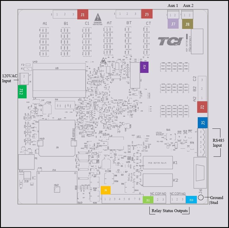
The PQconnect implements a Modbus RTU Master/Slave device, which supports two-wire RS-485
signal levels. The PQconnect communication port used for the Modbus RTU interface is connected
directly to the PCB. The communication port is located on the side of the PQconnect board.
5
4
3 Modbus RTU
2 Connections
1
Figure 10 – PQconnect Modbus RTU Connection
22MFC Kit Instructions 4.0 PQconnect Option
Modbus RTU Connections
The hardware pinout for the J5 communication header and default settings is shown below.
Table 5: Modbus Connector Pin Definitions
J5 Header
Signal Name Signal Type
Pinout
1 No connect -
2 D- RS-485 B (non-inverting)
3 GND RS-485 SC/G
4 D+ RS-485 A (inverting)
5 No connect -
The default protocol settings for the RS-485 Modbus RTU interface are shown below.
Table 6: Modbus RTU Protocol Settings
Parameter Default Value Units
Baud Rate 38400 Bd
Data Bits 8 Bits
Stop Bits 1 Bits
Parity Even -
Slave ID 10 -
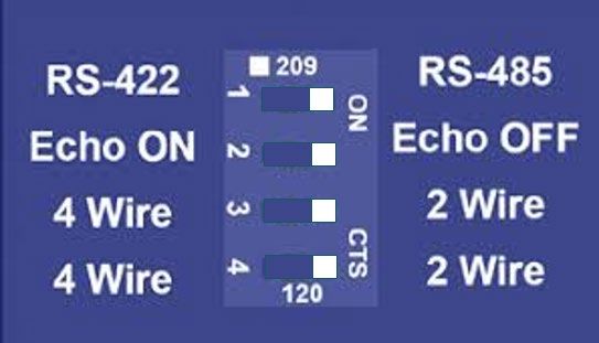
Table 7: Configuration Switches
1 – Enable 560Ω bias resistor on D-.
Configure Modbus Connection 2 – Enable 120Ω termination resistor.
SW1
on J5 Header
3 - Enable 560Ω pull-up on D+.
J20 Remove jumper to use default Modbus settings on next reboot.
The input registers from the Sinewave filter are mapped to Modbus register address 40000, see
Tables 14-16 for definitions of the input register maps. The output registers are mapped to
Modbus register address 40500, see Tables 8-12. All input and output registers are two bytes in
size and formatted as 16-bit signed integers.
23MFC Kit Instructions 4.0 PQconnect Option
Register Map
Read Parameters:
Table 8 : Network Interface OUTPUT/ Feedback Register Map
I/O Reg
Parameter Name Address Direction Format and Examples Description
Offset
0,1 = Initialization
2 = Power on Delay
3 = Fault Inhibit
4 = Reset Indicates the present state of the system
SYS_STATE 11 Output
5 = Nominal state machine.
6 = Fault Detected
7 = Calibrate offsets
8 = Calibrate Check
Two 8bit ASCII Characters
DSP_SW_VER 12 Output Software revision code for processor.
0x0141 = ASCII for "A1"
DSP_MODEL_NUM 13 Output 103 = 480 V System Model Number
V_OUT_A_RMS 30 Output Volts RMS Filter output RMS voltage phase A
4800 = 480.0 VRMSLL
V_OUT_B_RMS 31 Output Filter output RMS voltage phase B
Range: 120 to 690
V_OUT_C_RMS 32 Output VRMSLL Filter output RMS voltage phase C
Filter output Phase A THVD (Voltage
V_OUT_A_THD 45 Output
Total Harmonic Distortion)
% THVD
Filter output Phase B THVD (Voltage
V_OUT_B_THD 46 Output 50 = 5.0% THVD
Total Harmonic Distortion)
Filter output Phase C THVD (Voltage
V_OUT_C_THD 47 Output
Total Harmonic Distortion)
T_AMBIENT 48 Output 250 = 25.0 C° Filter internal ambient temperature
V_OUT_FUND_HZ 100 Output Range 1 to 500 Hz Filter output fundamental frequency
V_IN_CARRIER_HZ 101 Output Range 1kHz to 16 kHz Filter input carrier frequency
1 = ABC Rotation
Expected
V_OUT_ROT 102 Output Filter output phase orientation
2 = ACB Rotation
Expected
24MFC Kit Instructions 4.0 PQconnect Option
Read Parameters:
Table 9 : Network Interface OUTPUT/ Feedback Register Map
I/O Reg
Format and
Parameter Name Address Direction Description
Examples
Offset
FAULT_A 200 Output Example: Enabling all fault
conditions is 1111 1111 1111 1111
in binary or 65535 decimal.
FAULT_B 201 Output
0 = Disabled Reference Fault codes Table
FAULT_A_ENABLE_RO 202 Output If a fault is active and the bit
To Enable desired corresponding to that status in this
FAULT_B_ENABLE_RO 203 Output fault detections, enter mask is set, the relay will be
bit mask from table by activated.
converting to decimal
FAULT_A_RELAY_ACTION_RO 204 Output Range: 0 to 65535 Reference Fault codes Table
Read only values. To change these
FAULT_B_RELAY_ACTION_RO 205 Output values, modify the corresponding
register in the setpoint section
below.
0 = Power Off Indicates if the filter has input power
SYS_POWER 250 Output
1 = Power On available
0 = Filter is operating
1 = Filter has
SYS_FAULTED 251 Output Indicates filters status
detected a fault
condition
4800 = 480.0Vrms Filter rated voltage.
RATED_VOLTAGE_RO 260 Output Range = 1200 to
6900 Read only value.
Filter rated current.
1000 = 100.0 A
RATED_CURRENT_RO 261 Output
Range = 3 to 1500 A
Read only value.
Filter rated frequency
RATED_FEQUENCY_RO 262 Output 60 = 60 Hz
Read only value.
Modbus slave address
Default = 10 Read only value. To change this
MB_SLAVE_ADDRESS_RO 300 Output
Range 0 to 255 value, modify the corresponding
register in the setpoint section
below.
Modbus baud rate
960 = 9600 baud rate
3840 = 38400 baud
Read only value. To change this
MB_BAUD_RATE_RO 301 Output rate (default)
value, modify the corresponding
11520 = 115200 baud
register in the setpoint section
rate
below.
25MFC Kit Instructions 4.0 PQconnect Option
Read Parameters:
Table 10 : Network Interface OUTPUT / Feedback Register Map
I/O Reg
Format and
Parameter Name Address Direction Description
Examples
Offset
Modbus Parity
0 = None
1 = Odd
MB_PARITY_RO 302 Output Read only value. To change this
2 = Even
value, modify the corresponding
(default)
register in the setpoint section below.
Delay time on fault relay being
energized when any enabled fault
Relay close condition is detected. This delay is in
delay time in addition to any configured delay for a
CNT_CLOSE_DELAY_RO 320 Output milliseconds specific fault condition.
Range 0 to 60
seconds Read only value. To change this
value, modify the corresponding
register in the setpoint section below.
Delay time on fault relay being
Relay open unenergized when all enabled fault
delay time in detection conditions have cleared.
CNT_OPEN_DELAY_RO 321 Output milliseconds
Range 0 to 60 Read only value. To change this
seconds value, modify the corresponding
register in the setpoint section below.
Overvoltage onset threshold in
percent rated voltage
OVERVOLTAGE_FAULT_ONSET_RO 322 Output
Read only value. To change this
Default 125% value, modify the corresponding
Range 100 to register in the setpoint section below.
200 Overvoltage fault clear threshold
OVERVOLTAGE_FAULT_CLEAR_RO 323 Output Read only value. To change this
value, modify the corresponding
register in the setpoint section below.
Fault detection
delay time in Overvoltage fault delay time.
milliseconds.
OVERVOLTAGE_FAULT_DELAY_RO 324 Output Default of 6 Read only value. To change this
seconds. value, modify the corresponding
Range 0.02 to register in the setpoint section below.
60 seconds
Filter output high frequency fault
onset threshold
HIGH_FREQUENCY_FAULT_ONSET_RO 325 Output
Read only value. To change this
Default 125% value, modify the corresponding
Range 100 to register in the setpoint section below.
200 High frequency fault clear threshold
HIGH_FREQUENCY_FAULT_CLEAR_RO 326 Output Read only value. To change this
value, modify the corresponding
register in the setpoint section below.
Fault detection
delay time in High frequency fault delay time.
milliseconds.
HIGH_FREQUENCY_FAULT_DELAY_RO 327 Output Default of 6 Read only value. To change this
seconds. value, modify the corresponding
Range 0.02 to register in the setpoint section below.
60 seconds
26MFC Kit Instructions 4.0 PQconnect Option
Read Parameters:
Table 11 : Network Interface OUTPUT Register Map
I/O Reg
Format and
Parameter Name Address Direction Description
Examples
Offset
Phase loss fault onset threshold (average of
the three filter output voltages)
Default = 60 =
PHASE_LOSS_FAULT_ONSET_RO 328 Output 60%
Read only value. To change this value, modify
Range 1 to 100
the corresponding register in the setpoint
section below.
Phase loss fault clear threshold (average of
the three filter output voltages)
Default = 55 =
PHASE_LOSS_FAULT_CLEAR_RO 329 Output 55%
Read only value. To change this value, modify
Range 1 to 100
the corresponding register in the setpoint
section below.
Fault detection
delay time in Phase loss fault delay time.
milliseconds.
PHASE_LOSS_FAULT_DELAY_RO 330 Output Default of 12 Read only value. To change this value, modify
seconds. the corresponding register in the setpoint
Range 0.02 to section below.
60 seconds
Filter output high THVD fault onset threshold.
THD_FAULT_ONSET_RO 331 Output Read only value. To change this value, modify
the corresponding register in the setpoint
Default of 120 section below.
= 12.0% THD
Range 2 to 100 THVD fault clear threshold
THD_FAULT_CLEAR_RO 332 Output Read only value. To change this value, modify
the corresponding register in the setpoint
section below.
Fault detection
Voltage Total Harmonic Distortion (THVD)
delay time in
fault delay time.
milliseconds.
THD_FAULT_DELAY_RO 333 Output Default of 12
Read only value. To change this value, modify
seconds.
the corresponding register in the setpoint
Range 0.02 to
section below.
60 seconds
Filter Ambient overtemperature onset
threshold.
T_AMBIENT_OT_ONSET_RO 334 Output
Read only value. To change this value, modify
the corresponding register in the setpoint
Default = 20 = section below.
20%
Range 2 to 100 Filter Ambient overtemperature clear
threshold.
T_AMBIENT_OT_CLEAR_RO 335 Output
Read only value. To change this value, modify
the corresponding register in the setpoint
section below.
Fault detection
delay time in Filter Ambient overtemperature fault delay.
milliseconds.
T_AMBIENT_OT_DELAY_RO 336 Output Default of 12 Read only value. To change this value, modify
seconds. the corresponding register in the setpoint
Range 0.02 to section below.
60 seconds
Read Parameters:
27MFC Kit Instructions 4.0 PQconnect Option
Table 12 : Network Interface OUTPUT Register Map
I/O Reg
Format and
Parameter Name Address Direction Description
Examples
Offset
Fault detection delay Tuning reactor overtemperature fault
time in milliseconds. delay.
Default of 12
REACTOR_OT_DELAY_RO 337 Output
seconds. Read only value. To change this value,
Range 0.02 to 60 modify the corresponding register in the
seconds setpoint section below.
Parameter contains Unit serial number section - upper 16
UUUU in the bits of 32-bit unit job number
SYS_SERIAL_NUM_2_RO 350 Output
UUUULLLL-NN serial
number format. Read only value.
Parameter contains Unit serial number section - lower 16
LLLL in the bits of 32-bit unit job number
SYS_SERIAL_NUM_1_RO 351 Output
UUUULLLL-NN serial
number format. Read only value.
Parameter contains Unit serial number section - two-digit
NN in the unit number.
SYS_SERIAL_NUM_0_RO 352 Output
UUUULLLL- NN
serial number format. Read only value.
0 = Not calibrated
SYS_NULL_STAT 400 Output System auto null status
1 = Unit is calibrated
0 = Unit is not
System null timer; indicates whether the
SYS_NULL_TMR 401 Output calibrating
unit is calibrating
1 = Unit is Calibrating
Processor internal heartbeat. Internal
counter that counts up and rolls over to
SYS_INT_HB 402 Output Range 0 to 65535
zero used to verify processor clock
operation.
Processor background heartbeat.
Internal counter that counts up and rolls
SYS_BG_HB 403 Output Range 0 to 65535
over to zero used to verify processor
clock operation
28MFC Kit Instructions 4.0 PQconnect Option
Table 13 : Fault Codes
Bits Fault Descriptions
Register A
0 No fault detected / enabled
1 Overvoltage Phase A
2 Overvoltage Phase B
3 Overvoltage Phase C
4 High Frequency Phase A-B
5 High Frequency Phase B-C
6 High Frequency Phase C-A
7 Phase Loss (Phase A)
8 Phase Loss (Phase B)
9 Phase Loss (Phase C)
10 High THVD Phase A
11 High THVD Phase B
12 High THVD Phase C
13 Under Temperature
14 Over Temperature
15 CPU Error
Register B
0 Reactor Switch
29MFC Kit Instructions 4.0 PQconnect Option
Write Parameters:
Table 14 : Network Interface INPUT/Setpoint Register Map
I/O Reg
Format and
Parameter Name Address Direction Description
Examples
Offset
0 = Initialization
Note that defaulting the flash
9 = Save current
will clear all calibration data
values to flash
and require that the calibration
USER_STATE_REQ 500 Input 150 = Load values
procedure be re-run with no
from Flash
voltage applied to the
255 = Restore
PQconnect board.
Defaults to Flash
0 = Capture Done Update trace data points for
TRACE_GO_DONE 501 Input
1 = Start Capture waveforms
Delay time on fault relay being
Relay close delay energized when any enabled
time in milliseconds fault condition is detected. This
CNT_CLOSE_DELAY 505 Input
Range 0 to 60 delay is in addition to any
seconds configured delay for a specific
fault condition.
Relay open delay Delay time on fault relay being
time in milliseconds unenergized when all enabled
CNT_OPEN_DELAY 506 Input
Range 0 to 60 fault detection conditions have
seconds cleared.
Default 20 = 20
milliseconds
POWER_ON_DELAY 507 Input System power on delay
Range 0.02 to 60
Seconds.
1000 = 100 A
RATED_CURRENT 520 Input Filter rated current
Range = 3A to 1500A
4800 = 480 Vrms
RATED_VOLTAGE 521 Input Range = 120 to 690 Filter rated voltage
Vrms
50 = 50 Hz
RATED_FREQUENCY 522 Input Filter rated frequency
60 = 60 Hz
FAULT_A_ENABLE 540 Input Example: Enabling all fault
conditions is 1111 1111 1111
0 = Disabled 1111 in binary or 65535
FAULT_B_ENABLE 541 Input decimal.
To Enable desired
fault detections, enter Reference Fault codes Table 3
FAULT_A_RELAY_ACTION 542 Input bit mask from table by If a fault is active and the bit
converting to decimal corresponding to that status in
Range: 0 to 65535 this mask is set, the relay will
FAULT_B_RELAY_ACTION 543 Input be activated.
Reference Fault codes Table 3
DEFAULT = 10
MB_SLAVE_ADDRESS 560 Input Modbus slave address
Range 0 to 255
960 = 9600 baud rate
3840 = 38400 baud
MB_BAUD_RATE 561 Input rate (DEFAULT) Modbus baud rate
11520 = 115200 baud
rate
0 = None
MB_PARITY 562 Input 1 = Odd Modbus Parity
2 = Even (DEFAULT)
Write Parameters:
30MFC Kit Instructions 4.0 PQconnect Option
Table 15 : Network Interface INPUT Register Map
I/O Reg
Format and
Parameter Name Address Direction Description
Examples
Offset
Set desired Overvoltage
OVERVOLTAGE_FAULT_ONSET 600 Input onset threshold in percent
DEFAULT = 125% rated voltage
Range 100 to 200
Overvoltage fault clear
OVERVOLTAGE_FAULT_CLEAR 601 Input
threshold
Fault detection delay
time in milliseconds.
OVERVOLTAGE_FAULT_DELAY 602 Input Default of 12 seconds. Overvoltage fault delay time
Range 0.02 to 60
seconds
Default 125% Set desired High frequency
HIGH_FREQUENCY_FAULT_ONSET 603 Input
Range 100 to 200 fault onset threshold
Default 125% Set desired High frequency
HIGH_FREQUENCY_FAULT_CLEAR 604 Input
Range 100 to 200 fault clear threshold
Fault detection delay
time in milliseconds.
High frequency fault delay
HIGH_FREQUENCY_FAULT_DELAY 605 Input Default of 6 seconds.
time
Range 0.02 to 60
seconds
Phase loss fault onset
Default = 60 = 60%
PHASE_LOSS_FAULT_ONSET 606 Input threshold (average of the
Range 1 to 100
three filter output voltages)
Phase loss fault clear
Default = 55 = 55%
PHASE_LOSS_FAULT_CLEAR 607 Input threshold (average of the
Range 1 to 100
three filter output voltages)
Fault detection delay
time in milliseconds.
PHASE_LOSS_FAULT_DELAY 608 Input Default of 12 seconds. Phase loss fault delay time
Range 0.02 to 60
seconds
Default = 20 = 20% Set desired THVD fault
THD_FAULT_ONSET 609 Input
Range 2 to 100 onset threshold
Default = 20 = 20% Set desired THVD fault
THD_FAULT_CLEAR 610 Input
Range 2 to 100 clear threshold
Fault detection delay
time in milliseconds. Voltage Total Harmonic
THD_FAULT_DELAY 611 Input Default of 6 seconds. Distortion (THVD) fault
Range 0.02 to 60 delay time
seconds
Filter Ambient
Default = 20 = 20%
T_AMBIENT_OT_ONSET 612 Input overtemperature onset
Range 2 to 100
threshold
Filter Ambient
Default = 20 = 20%
T_AMBIENT_OT_CLEAR 613 Input overtemperature clear
Range 2 to 100
threshold
Fault detection delay Filter Ambient
T_AMBIENT_OT_DELAY 614 Input
time in milliseconds. overtemperature fault delay
Default of 12 seconds.
Range 0.02 to 60 Tuning reactor
REACTOR_OT_DELAY 615 Input
seconds overtemperature fault delay
31MFC Kit Instructions 4.0 PQconnect Option
Write Parameters:
Table 16 : Network Interface INPUT Register Map
System auto null calibration
0 = Disabled enable. This value auto
SYS_NULL_EN 700 Input
1 = Enabled clears to 0 when calibration
complete.
Parameter contains
Unit serial number section -
UUUU in the
SYS_SERIAL_NUM_2 810 Input upper 16 bits of 32-bit unit
UUUULLLL-NN serial
job number
number format.
Parameter contains
Unit serial number section -
LLLL in the
SYS_SERIAL_NUM_1 811 Input lower 16 bits of 32-bit unit
UUUULLLL-NN serial
job number
number format.
Parameter contains
NN in the UUUULLLL- Unit serial number section -
SYS_SERIAL_NUM_0 812 Input
NN serial number two-digit unit number
format.
PQconnect Hardware
Example Application Using “Simply Modbus Master 8.1.0”
The Modbus RTU network interface port is configured for RS-485 signal levels. The following
example uses an RS-485 to USB converter to connect the PQconnect to a laptop PC running the
Modbus RTU master application. The picture below shows an example “US Converters Model:
XS890” model RS-485 to USB converter. As another alternative RS-485 converter there is
WINGONEER USB 2.0 to RS485 Serial Converter Adapter CP2104.
Figure 11: B&B SmartWorx, Inc Model: USPTL4 model RS-422/485 converter
With the example converter above, the user can make proper connections from the RS485
converter to the PQconnect J5 communication header. The table below indicates the positions
where the RS485 connections lead to. Please ensure the correct dip switch settings are applied
before installing.
Table 17: USPTL4 to J5 Header Connections
USPTL4 Pin Out J5 Header Pinout
- No connect
TDA (-) A (Pin 2)
GND GND (Pin 3)
TDB(+) B (Pin 4)
- No connect
32You can also read