Modbus ASCII Driver - Kepware
←
→
Page content transcription
If your browser does not render page correctly, please read the page content below
Modbus ASCII Driver

    © 2021 PTC Inc. All Rights Reserved.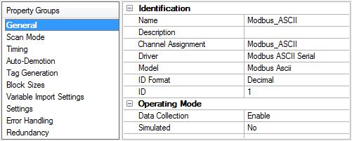
Modbus ASCII Driver                                                                                           2

 Table of Contents
      M odbus ASCII Driver                                                                               1

      Table of Contents                                                                                  2

        Modbus ASCII Driver                                                                              4

      Overview                                                                                           4

      Setup                                                                                              5
         Channel Properties — General                                                                    6
         Channel Properties — Serial Communications                                                      7
         Channel Properties — Write Optimizations                                                        9
         Channel Properties — Advanced                                                                  10
         Channel Properties — Communication Serialization                                               11
         Device Properties — General                                                                    12
         Device Properties — Scan Mode                                                                  13
         Device Properties — Timing                                                                     14
         Device Properties — Auto-Demotion                                                              15
         Device Properties — Tag Generation                                                             15
         Device Properties — Block Sizes                                                                17
         Device Properties — Variable Import Settings                                                   18
         Device Properties — Settings                                                                   19
         Device Properties — Error Handling                                                             21
         Device Properties — Redundancy                                                                 22

      Automatic Tag Database Generation                                                                 23

      Data Types Description                                                                            24

      Address Descriptions                                                                              25

        Modbus ASCII Addressing                                                                         25
         Function Codes Description                                                                     28

        Flow Computer Addressing                                                                        28

        Flow Automation Addressing                                                                      29

      Event Log M essages                                                                               30
         Bad address in block. | Block range =  to .                                  30
         Bad array. | Array range =  to .                                                   30
         Error opening file for tag database import. | OS error = ''.                            30
         Received block length does not match expected length. | Received length =  (bytes),
         Expected length =  (bytes).                                                            30
         Block request on device responded with exception. | Block Range =  to ,
         Exception = .                                                                            30
         Unable to write to address on device. Device responded with exception. | Address = '', 31

                                               www. ptc.com
3 M od b u s ASCII Driver
Exception = .
Unable to read from address on device. Device responded with exception. | Address =
'', Exception = . 31
Tag import failed due to low memory resources. 31
File exception encountered during tag import. 31
Error parsing record in import file. | Record number = , Field = . 32
Description truncated for record in import file. | Record number = . 32
Imported tag name is invalid and has been changed. | Tag name = '', Changed tag name =
''. 32
A tag could not be imported because the data type is not supported. | Tag name = '', Unsup-
ported data type = ''. 33
Importing tag database. | Source file = ''. 33
Modbus Exception Codes 34
Error Mask Definitions 35
Index 36
www. ptc.comModbus ASCII Driver 4
M odbus ASCII Driver
Help version 1.057
CONTENTS
Overview
What is the Modbus ASCII Driver?
Set up
How do I configure devices for use with this driver?
Aut omat ic Tag Dat abase Generat ion
How can I configure tags for the Modbus ASCII Driver?
Dat a Types Descript ion
What data types does this driver support?
Address Descript ions
How do I address a data location on a Modbus device?
Event Log M essages
What messages does the Modbus ASCII Driver produce?
Overview
The Modbus ASCII Driver provides a reliable way to connect Modbus ASCII serial devices to OPC Client applic-
ations; including HMI, SCADA, Historian, MES, ERP, and countless custom applications. It is intended for use
with serial devices that support the Modbus ASCII protocol. The driver's features provide control over the fol-
lowing: the amount of data requested from a device in a single request, the word ordering of 32-bit double
register values, the byte ordering of 32-bit and 16-bit register values, and address base adjustment. The
driver can also control the RTS line operation for use with radio modems that require specific RTS timing.
www. ptc.com5 M od b u s ASCII Driver
Set up
Supported Devices
Modbus ASCII compatible devices
Flow Computers using the Daniels/Omni/Elliot register addressing
Communication Protocol
Modbus ASCII Protocol
Channel and Device Limits
The maximum number of channels supported by this driver is 100. The maximum number of devices sup-
ported by this driver is 247 per channel.
Ethernet Encapsulation
This driver supports Ethernet Encapsulation, which allows the driver to communicate with serial devices
attached to an Ethernet network using a terminal server. It may be invoked through the COM ID dialog in
Channel Properties. For more information, refer to the server help file.
Supported Communication Properties
Baud Rate: 1200, 2400, 9600, 19200
Parity: Odd, Even, None
Data Bits: 8
Stop Bits: 1,2
N ote: Some devices may not support the listed configurations.
Flow Control
When using an RS232 / RS485 converter, the type of flow control that is required depends on the needs of
the converter. Some converters do not require any flow control whereas others require RTS flow. Consult the
converter's documentation to determine its flow requirements. An RS485 converter that provides automatic
flow control is recommended.
N otes:
1. When using the manufacturer's supplied communications cable, it is sometimes necessary to choose
a flow control setting of RTS or RTS Always under the channel properties.
2. The Modbus ASCII Driver supports the RTS Manual flow control option. This selection is used to con-
figure the driver for operation with radio modems that require special RTS timing characteristics. For
more information on RTS Manual flow control, refer to the server help file.
Communication Serialization
The Modbus ASCII Driver supports communication serialization, which specifies whether data transmissions
should be limited to one channel at a time.
www. ptc.comModbus ASCII Driver 6
Channel Propert ies — General
This server supports the use of multiple simultaneous communications drivers. Each protocol or driver used
in a server project is called a channel. A server project may consist of many channels with the same com-
munications driver or with unique communications drivers. A channel acts as the basic building block of an
OPC link. This group is used to specify general channel properties, such as the identification attributes and
operating mode.
Identification
N am e: Specify the user-defined identity of this channel. In each server project, each channel name must be
unique. Although names can be up to 256 characters, some client applications have a limited display window
when browsing the OPC server's tag space. The channel name is part of the OPC browser information. The
property is required for creating a channel.
For information on reserved characters, refer to "How To... Properly Name a Channel, Device, Tag, and Tag
Group" in the server help.
Description: Specify user-defined information about this channel.
Many of these properties, including Description, have an associated system tag.
Driver: Specify the protocol / driver for this channel. This property specifies the device driver that was selec-
ted during channel creation. It is a disabled setting in the channel properties. The property is required for cre-
ating a channel.
N ote: With the server's online full-time operation, these properties can be changed at any time. This
includes changing the channel name to prevent clients from registering data with the server. If a client has
already acquired an item from the server before the channel name is changed, the items are unaffected. If,
after the channel name has been changed, the client application releases the item and attempts to re-
acquire using the old channel name, the item is not accepted. Changes to the properties should not be made
once a large client application has been developed. Utilize proper user role and privilege management to
prevent operators from changing properties or accessing server features.
Diagnostics
Diagnostics Capture: When enabled, this option makes the channel's diagnostic information available to
OPC applications. Because the server's diagnostic features require a minimal amount of overhead pro-
cessing, it is recommended that they be utilized when needed and disabled when not. The default is dis-
abled.
N ote: This property is not available if the driver does not support diagnostics.
For more information, refer to "Communication Diagnostics" and "Statistics Tags" in the server help.
www. ptc.com7 M od b u s ASCII Driver
Channel Propert ies — Serial Com m unicat ions
Serial communication properties are available to serial drivers and vary depending on the driver, connection
type, and options selected. Below is a superset of the possible properties.
Click to jump to one of the sections: Connection Type, Serial Port Settings or Ethernet Settings, and
Operational Behavior.
N ote: With the server's online full-time operation, these properties can be changed at any time. Utilize
proper user role and privilege management to prevent operators from changing properties or accessing
server features.
Connection Type
Physical Medium : Choose the type of hardware device for data communications. Options include
COM Port, None, Modem, and Ethernet Encapsulation. The default is COM Port.
l N one: Select None to indicate there is no physical connection, which displays the Operation with no
Com m unications section.
l COM Port: Select Com Port to display and configure the Serial Port Settings section.
l Modem : Select Modem if phone lines are used for communications, which are configured in the
Modem Settings section.
l Ethernet Encap.: Select if Ethernet Encapsulation is used for communications, which displays the
Ethernet Settings section.
l Shared: Verify the connection is correctly identified as sharing the current configuration with another
channel. This is a read-only property.
Serial Port Settings
COM ID: Specify the Communications ID to be used when communicating with devices assigned to the chan-
nel. The valid range is 1 to 9991 to 16. The default is 1.
Baud Rate: Specify the baud rate to be used to configure the selected communications port.
Data Bits: Specify the number of data bits per data word. Options include 5, 6, 7, or 8.
Parity: Specify the type of parity for the data. Options include Odd, Even, or None.
www. ptc.comModbus ASCII Driver 8
Stop Bits: Specify the number of stop bits per data word. Options include 1 or 2.
Flow Control: Select how the RTS and DTR control lines are utilized. Flow control is required to communicate
with some serial devices. Options are:
l N one: This option does not toggle or assert control lines.
l DTR: This option asserts the DTR line when the communications port is opened and remains on.
l RTS: This option specifies that the RTS line is high if bytes are available for transmission. After all buf-
fered bytes have been sent, the RTS line is low. This is normally used with RS232/RS485 converter
hardware.
l RTS, DTR: This option is a combination of DTR and RTS.
l RTS Always: This option asserts the RTS line when the communication port is opened and remains
on.
l RTS Manual: This option asserts the RTS line based on the timing properties entered for RTS Line
Control. It is only available when the driver supports manual RTS line control (or when the properties
are shared and at least one of the channels belongs to a driver that provides this support).
RTS Manual adds an RTS Line Control property with options as follows:
l Raise: This property specifies the amount of time that the RTS line is raised prior to data
transmission. The valid range is 0 to 9999 milliseconds. The default is 10 milliseconds.
l Drop: This property specifies the amount of time that the RTS line remains high after data
transmission. The valid range is 0 to 9999 milliseconds. The default is 10 milliseconds.
l Poll Delay: This property specifies the amount of time that polling for communications is
delayed. The valid range is 0 to 9999. The default is 10 milliseconds.
Tip: When using two-wire RS-485, "echoes" may occur on the communication lines. Since this com-
munication does not support echo suppression, it is recommended that echoes be disabled or a RS-485 con-
verter be used.
Operational Behavior
l Report Com m unication Errors: Enable or disable reporting of low-level communications errors.
When enabled, low-level errors are posted to the Event Log as they occur. When disabled, these
same errors are not posted even though normal request failures are. The default is Enable.
l Close Idle Connection: Choose to close the connection when there are no longer any tags being ref-
erenced by a client on the channel. The default is Enable.
l Idle Tim e to Close: Specify the amount of time that the server waits once all tags have been
removed before closing the COM port. The default is 15 seconds.
Ethernet Settings
N ote: Not all serial drivers support Ethernet Encapsulation. If this group does not appear, the functionality
is not supported.
Ethernet Encapsulation provides communication with serial devices connected to terminal servers on the
Ethernet network. A terminal server is essentially a virtual serial port that converts TCP/IP messages on the
Ethernet network to serial data. Once the message has been converted, users can connect standard devices
that support serial communications to the terminal server. The terminal server's serial port must be prop-
erly configured to match the requirements of the serial device to which it is attached. For more information,
refer to "Using Ethernet Encapsulation" in the server help.
l N etwork Adapter: Indicate a network adapter to bind for Ethernet devices in this channel. Choose a
network adapter to bind to or allow the OS to select the default.
www. ptc.com9 M od b u s ASCII Driver
Specific drivers may display additional Ethernet Encapsulation properties. For more information, refer
to Channel Properties — Ethernet Encapsulation.
M odem Settings
l Modem : Specify the installed modem to be used for communications.
l Connect Tim eout: Specify the amount of time to wait for connections to be established before failing
a read or write. The default is 60 seconds.
l Modem Properties: Configure the modem hardware. When clicked, it opens vendor-specific modem
properties.
l Auto-Dial: Enables the automatic dialing of entries in the Phonebook. The default is Disable. For more
information, refer to "Modem Auto-Dial" in the server help.
l Report Com m unication Errors: Enable or disable reporting of low-level communications errors.
When enabled, low-level errors are posted to the Event Log as they occur. When disabled, these
same errors are not posted even though normal request failures are. The default is Enable.
l Close Idle Connection: Choose to close the modem connection when there are no longer any tags
being referenced by a client on the channel. The default is Enable.
l Idle Tim e to Close: Specify the amount of time that the server waits once all tags have been
removed before closing the modem connection. The default is 15 seconds.
Operation w ith no Communications
l Read Processing: Select the action to be taken when an explicit device read is requested. Options
include Ignore and Fail. Ignore does nothing; Fail provides the client with an update that indicates fail-
ure. The default setting is Ignore.
Channel Propert ies — Writ e Opt im izat ions
The server must ensure that the data written from the client application gets to the device on time. Given
this goal, the server provides optimization properties to meet specific needs or improve application respons-
iveness.
Write Optimizations
Optim ization Method: Controls how write data is passed to the underlying communications driver. The
options are:
l Write All Values for All Tags: This option forces the server to attempt to write every value to the
controller. In this mode, the server continues to gather write requests and add them to the server's
internal write queue. The server processes the write queue and attempts to empty it by writing data
to the device as quickly as possible. This mode ensures that everything written from the client applic-
ations is sent to the target device. This mode should be selected if the write operation order or the
write item's content must uniquely be seen at the target device.
l Write Only Latest Value for N on-Boolean Tags: Many consecutive writes to the same value can
accumulate in the write queue due to the time required to actually send the data to the device. If the
www. ptc.comModbus ASCII Driver 10
server updates a write value that has already been placed in the write queue, far fewer writes are
needed to reach the same final output value. In this way, no extra writes accumulate in the server's
queue. When the user stops moving the slide switch, the value in the device is at the correct value at
virtually the same time. As the mode states, any value that is not a Boolean value is updated in the
server's internal write queue and sent to the device at the next possible opportunity. This can greatly
improve the application performance.
N ote: This option does not attempt to optimize writes to Boolean values. It allows users to optimize
the operation of HMI data without causing problems with Boolean operations, such as a momentary
push button.
l Write Only Latest Value for All Tags: This option takes the theory behind the second optimization
mode and applies it to all tags. It is especially useful if the application only needs to send the latest
value to the device. This mode optimizes all writes by updating the tags currently in the write queue
before they are sent. This is the default mode.
Duty Cycle: is used to control the ratio of write to read operations. The ratio is always based on one read for
every one to ten writes. The duty cycle is set to ten by default, meaning that ten writes occur for each read
operation. Although the application is performing a large number of continuous writes, it must be ensured
that read data is still given time to process. A setting of one results in one read operation for every write
operation. If there are no write operations to perform, reads are processed continuously. This allows optim-
ization for applications with continuous writes versus a more balanced back and forth data flow.
N ote: It is recommended that the application be characterized for compatibility with the write optimization
enhancements before being used in a production environment.
Channel Propert ies — Advanced
This group is used to specify advanced channel properties. Not all drivers support all properties; so the
Advanced group does not appear for those devices.
N on-N orm alized Float Handling: A non-normalized value is defined as Infinity, Not-a-Number (NaN), or as
a Denormalized Number. The default is Replace with Zero. Drivers that have native float handling may
default to Unmodified. Non-normalized float handling allows users to specify how a driver handles non-nor-
malized IEEE-754 floating point data. Descriptions of the options are as follows:
l Replace with Zero: This option allows a driver to replace non-normalized IEEE-754 floating point val-
ues with zero before being transferred to clients.
l Unm odified: This option allows a driver to transfer IEEE-754 denormalized, normalized, non-num-
ber, and infinity values to clients without any conversion or changes.
N ote: This property is not available if the driver does not support floating-point values or if it only supports
the option that is displayed. According to the channel's float normalization setting, only real-time driver tags
(such as values and arrays) are subject to float normalization. For example, EFM data is not affected by this
setting.
For more information on the floating point values, refer to "How To ... Work with Non-Normalized Floating
Point Values" in the server help.
www. ptc.com11 M od b u s ASCII Driver
Inter-Device Delay: Specify the amount of time the communications channel waits to send new requests to
the next device after data is received from the current device on the same channel. Zero (0) disables the
delay.
N ote: This property is not available for all drivers, models, and dependent settings.
Channel Propert ies — Com m unicat ion Serializat ion
The server's multi-threading architecture allows channels to communicate with devices in parallel. Although
this is efficient, communication can be serialized in cases with physical network restrictions (such as Eth-
ernet radios). Communication serialization limits communication to one channel at a time within a virtual net-
work.
The term "virtual network" describes a collection of channels and associated devices that use the same
pipeline for communications. For example, the pipeline of an Ethernet radio is the client radio. All channels
using the same client radio associate with the same virtual network. Channels are allowed to communicate
each in turn, in a "round-robin" manner. By default, a channel can process one transaction before handing
communications off to another channel. A transaction can include one or more tags. If the controlling chan-
nel contains a device that is not responding to a request, the channel cannot release control until the trans-
action times out. This results in data update delays for the other channels in the virtual network.
Channel-Level Settings
Virtual N etwork: Specify the channel's mode of communication serialization. Options include None and Net-
work 1 - Network 500. The default is None. Descriptions of the options are as follows:
l N one: This option disables communication serialization for the channel.
l N etwork 1 - N etwork 500: This option specifies the virtual network to which the channel is
assigned.
Transactions per Cycle: Specify the number of single blocked/non-blocked read/write transactions that can
occur on the channel. When a channel is given the opportunity to communicate, this is the number of trans-
actions attempted. The valid range is 1 to 99. The default is 1.
Global Settings
l N etwork Mode: This property is used to control how channel communication is delegated. In Load
Balanced mode, each channel is given the opportunity to communicate in turn, one at a time. In Pri-
ority mode, channels are given the opportunity to communicate according to the following rules
(highest to lowest priority):
l Channels with pending writes have the highest priority.
l Channels with pending explicit reads (through internal plug-ins or external client interfaces)
are prioritized based on the read's priority.
l Scanned reads and other periodic events (driver specific).
www. ptc.comModbus ASCII Driver 12
The default is Load Balanced and affects all virtual networks and channels.
Devices that rely on unsolicited responses should not be placed in a virtual network. In situations where
communications must be serialized, it is recommended that Auto-Demotion be enabled.
Due to differences in the way that drivers read and write data (such as in single, blocked, or non-blocked
transactions); the application's Transactions per cycle property may need to be adjusted. When doing so,
consider the following factors:
l How many tags must be read from each channel?
l How often is data written to each channel?
l Is the channel using a serial or Ethernet driver?
l Does the driver read tags in separate requests, or are multiple tags read in a block?
l Have the device's Timing properties (such as Request timeout and Fail after x successive timeouts)
been optimized for the virtual network's communication medium?
Device Propert ies — General
Identification
N am e: User-defined identity of this device.
Description: User-defined information about this device.
Channel Assignm ent: User-defined name of the channel to which this device currently belongs.
Driver: Selected protocol driver for this device.
Model: The specific version of the device.
ID Form at: Select how the device identity is formatted. Options include Decimal, Octal, and Hex.
ID: the unique device number. Modbus Serial devices are assigned device IDs in the range of 1 to 247.
Operating M ode
www. ptc.com13 M od b u s ASCII Driver
Data Collection: This property controls the device's active state. Although device communications are
enabled by default, this property can be used to disable a physical device. Communications are not attemp-
ted when a device is disabled. From a client standpoint, the data is marked as invalid and write operations
are not accepted. This property can be changed at any time through this property or the device system tags.
Sim ulated: This option places the device into Simulation Mode. In this mode, the driver does not attempt to
communicate with the physical device, but the server continues to return valid OPC data. Simulated stops
physical communications with the device, but allows OPC data to be returned to the OPC client as valid data.
While in Simulation Mode, the server treats all device data as reflective: whatever is written to the simulated
device is read back and each OPC item is treated individually. The item's memory map is based on the group
Update Rate. The data is not saved if the server removes the item (such as when the server is reinitialized).
The default is No.
N otes:
1. This System tag (_Simulated) is read only and cannot be written to for runtime protection. The System
tag allows this property to be monitored from the client.
2. In Simulation mode, the item's memory map is based on client update rate(s) (Group Update Rate for
OPC clients or Scan Rate for native and DDE interfaces). This means that two clients that reference
the same item with different update rates return different data.
Simulation Mode is for test and simulation purposes only. It should never be used in a production envir-
onment.
Device Propert ies — Scan M ode
The Scan Mode specifies the subscribed-client requested scan rate for tags that require device com-
munications. Synchronous and asynchronous device reads and writes are processed as soon as possible;
unaffected by the Scan Mode properties.
Scan Mode: Specify how tags in the device are scanned for updates sent to subscribing clients. Descriptions
of the options are:
l Respect Client-Specified Scan Rate: This mode uses the scan rate requested by the client.
l Request Data N o Faster than Scan Rate: This mode specifies the value set as the maximum scan
rate. The valid range is 10 to 99999990 milliseconds. The default is 1000 milliseconds.
N ote: When the server has an active client and items for the device and the scan rate value is
increased, the changes take effect immediately. When the scan rate value is decreased, the changes
do not take effect until all client applications have been disconnected.
l Request All Data at Scan Rate: This mode forces tags to be scanned at the specified rate for sub-
scribed clients. The valid range is 10 to 99999990 milliseconds. The default is 1000 milliseconds.
l Do N ot Scan, Dem and Poll Only: This mode does not periodically poll tags that belong to the
device nor perform a read to get an item's initial value once it becomes active. It is the client's
responsibility to poll for updates, either by writing to the _DemandPoll tag or by issuing explicit device
reads for individual items. For more information, refer to "Device Demand Poll" in server help.
www. ptc.comModbus ASCII Driver 14
l Respect Tag-Specified Scan Rate: This mode forces static tags to be scanned at the rate specified
in their static configuration tag properties. Dynamic tags are scanned at the client-specified scan
rate.
Initial Updates from Cache: When enabled, this option allows the server to provide the first updates for
newly activated tag references from stored (cached) data. Cache updates can only be provided when the
new item reference shares the same address, scan rate, data type, client access, and scaling properties. A
device read is used for the initial update for the first client reference only. The default is disabled; any time a
client activates a tag reference the server attempts to read the initial value from the device.
Device Propert ies — Tim ing
The device Timing properties allow the driver's response to error conditions to be tailored to fit the applic-
ation's needs. In many cases, the environment requires changes to these properties for optimum per-
formance. Factors such as electrically generated noise, modem delays, and poor physical connections can
influence how many errors or timeouts a communications driver encounters. Timing properties are specific
to each configured device.
Communications Timeouts
Connect Tim eout: This property (which is used primarily by Ethernet based drivers) controls the amount of
time required to establish a socket connection to a remote device. The device's connection time often takes
longer than normal communications requests to that same device. The valid range is 1 to 30 seconds. The
default is typically 3 seconds, but can vary depending on the driver's specific nature. If this setting is not sup-
ported by the driver, it is disabled.
N ote: Due to the nature of UDP connections, the connection timeout setting is not applicable when com-
municating via UDP.
Request Tim eout: Specify an interval used by all drivers to determine how long the driver waits for a
response from the target device to complete. The valid range is 50 to 9,999,999 milliseconds (167.6667
minutes). The default is usually 1000 milliseconds, but can vary depending on the driver. The default timeout
for most serial drivers is based on a baud rate of 9600 baud or better. When using a driver at lower baud
rates, increase the timeout to compensate for the increased time required to acquire data.
Attem pts Before Tim eout: Specify how many times the driver issues a communications request before con-
sidering the request to have failed and the device to be in error. The valid range is 1 to 10. The default is typ-
ically 3, but can vary depending on the driver's specific nature. The number of attempts configured for an
application depends largely on the communications environment. This property applies to both connection
attempts and request attempts.
Timing
Inter-Request Delay: Specify how long the driver waits before sending the next request to the target
device. It overrides the normal polling frequency of tags associated with the device, as well as one-time
reads and writes. This delay can be useful when dealing with devices with slow turnaround times and in
cases where network load is a concern. Configuring a delay for a device affects communications with all
www. ptc.com15 M od b u s ASCII Driver
other devices on the channel. It is recommended that users separate any device that requires an inter-
request delay to a separate channel if possible. Other communications properties (such as communication
serialization) can extend this delay. The valid range is 0 to 300,000 milliseconds; however, some drivers may
limit the maximum value due to a function of their particular design. The default is 0, which indicates no
delay between requests with the target device.
N ote: Not all drivers support Inter-Request Delay. This setting does not appear if it is not available.
Device Propert ies — Aut o-Dem ot ion
The Auto-Demotion properties can temporarily place a device off-scan in the event that a device is not
responding. By placing a non-responsive device offline for a specific time period, the driver can continue to
optimize its communications with other devices on the same channel. After the time period has been
reached, the driver re-attempts to communicate with the non-responsive device. If the device is responsive,
the device is placed on-scan; otherwise, it restarts its off-scan time period.
Dem ote on Failure: When enabled, the device is automatically taken off-scan until it is responding again.
Tip: Determine when a device is off-scan by monitoring its demoted state using the _AutoDemoted sys-
tem tag.
Tim eouts to Dem ote: Specify how many successive cycles of request timeouts and retries occur before the
device is placed off-scan. The valid range is 1 to 30 successive failures. The default is 3.
Dem otion Period: Indicate how long the device should be placed off-scan when the timeouts value is
reached. During this period, no read requests are sent to the device and all data associated with the read
requests are set to bad quality. When this period expires, the driver places the device on-scan and allows for
another attempt at communications. The valid range is 100 to 3600000 milliseconds. The default is 10000
milliseconds.
Discard Requests when Dem oted: Select whether or not write requests should be attempted during the
off-scan period. Disable to always send write requests regardless of the demotion period. Enable to discard
writes; the server automatically fails any write request received from a client and does not post a message
to the Event Log.
Device Propert ies — Tag Generat ion
The automatic tag database generation features make setting up an application a plug-and-play operation.
Select communications drivers can be configured to automatically build a list of tags that correspond to
device-specific data. These automatically generated tags (which depend on the nature of the supporting
driver) can be browsed from the clients.
Not all devices and drivers support full automatic tag database generation and not all support the same data
types. Consult the data types descriptions or the supported data type lists for each driver for specifics.
If the target device supports its own local tag database, the driver reads the device's tag information and
uses the data to generate tags within the server. If the device does not natively support named tags, the
www. ptc.comModbus ASCII Driver 16
driver creates a list of tags based on driver-specific information. An example of these two conditions is as fol-
lows:
1. If a data acquisition system supports its own local tag database, the communications driver uses the
tag names found in the device to build the server's tags.
2. If an Ethernet I/O system supports detection of its own available I/O module types, the com-
munications driver automatically generates tags in the server that are based on the types of I/O mod-
ules plugged into the Ethernet I/O rack.
N ote: Automatic tag database generation's mode of operation is completely configurable. For more inform-
ation, refer to the property descriptions below.
On Property Change: If the device supports automatic tag generation when certain properties change, the
On Property Change option is shown. It is set to Yes by default, but it can be set to N o to control over when
tag generation is performed. In this case, the Create tags action must be manually invoked to perform tag
generation.
On Device Startup: Specify when OPC tags are automatically generated. Descriptions of the options are as
follows:
l Do N ot Generate on Startup: This option prevents the driver from adding any OPC tags to the tag
space of the server. This is the default setting.
l Always Generate on Startup: This option causes the driver to evaluate the device for tag inform-
ation. It also adds tags to the tag space of the server every time the server is launched.
l Generate on First Startup: This option causes the driver to evaluate the target device for tag
information the first time the project is run. It also adds any OPC tags to the server tag space as
needed.
N ote: When the option to automatically generate OPC tags is selected, any tags that are added to the
server's tag space must be saved with the project. Users can configure the project to automatically save
from the Tools | Options menu.
On Duplicate Tag: When automatic tag database generation is enabled, the server needs to know what to
do with the tags that it may have previously added or with tags that have been added or modified after the
communications driver since their original creation. This setting controls how the server handles OPC tags
that were automatically generated and currently exist in the project. It also prevents automatically gen-
erated tags from accumulating in the server.
For example, if a user changes the I/O modules in the rack with the server configured to Always Generate
on Startup, new tags would be added to the server every time the communications driver detected a new
I/O module. If the old tags were not removed, many unused tags could accumulate in the server's tag space.
The options are:
www. ptc.com17 M od b u s ASCII Driver
l Delete on Create: This option deletes any tags that were previously added to the tag space before
any new tags are added. This is the default setting.
l Overwrite as N ecessary: This option instructs the server to only remove the tags that the com-
munications driver is replacing with new tags. Any tags that are not being overwritten remain in the
server's tag space.
l Do not Overwrite: This option prevents the server from removing any tags that were previously gen-
erated or already existed in the server. The communications driver can only add tags that are com-
pletely new.
l Do not Overwrite, Log Error: This option has the same effect as the prior option, and also posts an
error message to the server's Event Log when a tag overwrite would have occurred.
N ote: Removing OPC tags affects tags that have been automatically generated by the com-
munications driver as well as any tags that have been added using names that match generated tags.
Users should avoid adding tags to the server using names that may match tags that are automatically
generated by the driver.
Parent Group: This property keeps automatically generated tags from mixing with tags that have been
entered manually by specifying a group to be used for automatically generated tags. The name of the group
can be up to 256 characters. This parent group provides a root branch to which all automatically generated
tags are added.
Allow Autom atically Generated Subgroups: This property controls whether the server automatically cre-
ates subgroups for the automatically generated tags. This is the default setting. If disabled, the server gen-
erates the device's tags in a flat list without any grouping. In the server project, the resulting tags are named
with the address value. For example, the tag names are not retained during the generation process.
N ote: If, as the server is generating tags, a tag is assigned the same name as an existing tag, the system
automatically increments to the next highest number so that the tag name is not duplicated. For example, if
the generation process creates a tag named "AI22" that already exists, it creates the tag as "AI23" instead.
Create: Initiates the creation of automatically generated OPC tags. If the device's configuration has been
modified, Create tags forces the driver to reevaluate the device for possible tag changes. Its ability to be
accessed from the System tags allows a client application to initiate tag database creation.
N ote: Create tags is disabled if the Configuration edits a project offline.
Device Propert ies — Block Sizes
Coils
www. ptc.comModbus ASCII Driver 18
Output Coils: Coils can be read from 8 to 2000 points (bits) at a time. A higher block size means more
points are read from the device in a single request. Block size can be reduced if data needs to be read from
non-contiguous locations within the device.
Input Coils: Coils can be read from 8 to 2000 points (bits) at a time. A higher block size means more points
are read from the device in a single request. Block size can be reduced if data needs to be read from non-
contiguous locations within the device.
Registers
Internal Registers: Registers can be read from 1 to 100 locations (words) at a time. A higher block size
means more register values are read from the device in a single request. Block size can be reduced if data
needs to be read from non-contiguous locations within the device.
Holding Registers: Registers can be read from 1 to 100 locations (words) at a time. A higher block size
means more register values are read from the device in a single request. Block size can be reduced if data
needs to be read from non-contiguous locations within the device.
Caution: If the register block sizes value is set above 120 and a 32- or 64-bit data type is used for any tag,
an error can occur. To prevent errors from occurring, decrease the block size value to 120.
Block Sizes
Block Read Strings: Enable this option to block read string tags, which are normally read individually. When
this option is enabled, string tags are grouped together depending on the selected block size. Block reads
can only be performed for Modbus model string tags.
Device Propert ies — Variable Im port Set t ings
For more information on CSV files for Modbus Drivers, refer to Creating CSV Files for Modbus Drivers.
Variable Im port File: Specifies the exact location and name of the semicolon-delimited text file the driver
should use for automatic tag generation. Variable import files can be created from many applications.
Include Descriptions: When enabled, tag descriptions are imported if present in the file. The default setting
is enabled.
For more information on configuring the Automatic Tag Database Generation feature and creating a variable
import file, refer to Automatic Tag Database Generation.
For specific information on creating the variable import file from Concept and ProWORX, consult Technical
Note "Creating CSV Files for Modbus Drivers."
www. ptc.com19 M od b u s ASCII Driver
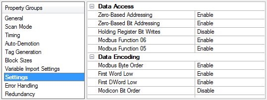
Device Propert ies — Set t ings
Data Access
Zero-Based Addressing : If the address numbering convention for the device starts at one as opposed to
zero, users can specify it when defining the device's properties. By default, user-entered addresses have
one subtracted when frames are constructed to communicate with a Modbus device. If the device doesn't fol-
low this convention, users can disable the zero-based addressing. The default behavior (zero-based) follows
the convention of the Modicon PLCs.
Zero-Based Bit Addressing: For memory types that allow bits within Words can be referenced as a
Boolean, the addressing notation is . where represents the bit number within the Word.
Addressing within registers provides two ways of addressing a bit within a given Word. Zero-based bit
addressing within registers means the first bit begins at 0. One-based addressing within registers means
that the first bit begins at 1. For data type Word, the bit range with zero-bit addressing is 0-15; whereas the
range for one-based bit addressing is 1-16.
Holding Register Bit Writes: When writing to a bit location within a holding register, the driver should only
modify the bit of interest. Some devices support a command to manipulate a single bit within a register
(Function code hex 0x16 or decimal 22). If the device does not support this feature, the driver must perform
a Read/Modify/Write operation to ensure that only the single bit is changed. Enable if the device supports
holding register bit access. The default setting is disabled. If this setting is enabled, the driver uses function
code 0x16 regardless of the setting for Modbus Function 06 for register writes. If this setting is not selected,
the driver uses either function code 0x06 or 0x10, depending on the setting for Modbus Function 06.
N ote: When Modbus byte order is not selected, the byte order of the masks sent in the command is Intel
byte order.
Modbus Function 06: The Modbus driver has the option of using two Modbus protocol functions to write
holding register data to the target device. In most cases, the driver switches between these two functions
based on the number of registers being written. When writing a single 16-bit register, the driver generally
uses Modbus function 06. When writing a 32-bit value into two registers, the driver uses Modbus function 16.
For the standard Modicon PLC, the use of either of these functions is not a problem. There are, however, a
number of third-party devices using the Modbus protocol and many of these devices support only the use of
Modbus function 16 to write to holding registers regardless of the number of registers to be written. Use
function 06 can be used to force the driver to use only Modbus function 16 if needed. This selection is
enabled by default. It allows the driver to switch between 06 and 16 as needed. If the device requires all
writes to be done using only Modbus function 16, disable this selection.
www. ptc.comModbus ASCII Driver 20
N ote: For bit within word writes, the Holding Register Bit Writes property takes precedence over this prop-
erty (Modbus Function 06). If Holding Register Bit Writes is selected, then function code 0x16 is used regard-
less of the selection for this property. However, if Holding Register Bit Writes is not selected, depending on
the selection of this property, either function code 0x06 or 0x10 is used for bit within word writes.
Use Function 05: The Modbus driver has the option of using two Modbus protocol functions to write output
coil data to the target device. In most cases, the driver switches between these two functions based on the
number of coils being written. When writing a single coil, the driver uses Modbus function 05. When writing
an array of coils, the driver uses Modbus function 15. For the standard Modicon PLC, the use of either of
these functions is not a problem. There are, however, a number of third-party devices using the Modbus pro-
tocol and many of these devices support only the use of Modbus function 15 to write to output coils regard-
less of the number of coils to be written. Modbus Function 05 can be used to force the driver to use only
Modbus function 15 if needed. This selection is enabled by default. It allows the driver to switch between 05
and 15 as needed. If a device requires all writes to be done using only Modbus function 15, disable this selec-
tion.
Data Encoding
Modbus Byte Order: The driver's byte order can be changed from the default Modbus byte ordering to Intel
byte ordering by using this selection. Modbus Byte Order sets the data encoding of each register / 16-bit
value. This election is enabed by default, which is the normal setting for Modbus compatible devices. If the
device uses Intel byte ordering, disabling this selection allows the Modbus driver to properly read Intel
formatted data.
First Word Low: Two consecutive registers' addresses in a Modbus device are used for 32-bit data types.
Users can specify whether the driver should assume the first word is the low or the high word of the 32-bit
value and each double word of a 64-bit value. The default, first word low, follows the convention of the
Modicon Modsoft programming software.
First DWord Low: Four consecutive registers' addresses in a Modbus device are used for 64-bit data types.
Users can specify whether the driver should assume the first DWord is the low or the high DWord of the 64-
bit value. The default, first DWord low, follows the default convention of 64-bit data types.
Modicon Bit Order: When enabled, the driver reverses the bit order on reads and writes to registers to fol-
low the convention of the Modicon Modsoft programming software. For example, a write to address
40001.0/1 affects bit 15/16 in the device when this option is enabled. This option is disabled by default.
N ote: For the following example, the 1st through 16th bit signifies either 0-15 bits or 1-16 bits depending
on if the driver is set at zero-based or one-based bit addressing within registers.
MSB = Most Significant Bit
LSB = Least Significant Bit
Modicon Bit Order Enabled
M SB LSB
1 2 3 4 5 6 7 8 9 10 11 12 13 14 15 16
Modicon Bit Order Disabled
M SB LSB
16 15 14 13 12 11 10 9 8 7 6 5 4 3 2 1
www. ptc.com21 M od b u s ASCII Driver
Dat a Types M odbus Byt e Order First Word Low First DWord Low
Word, Short, BCD Applicable N/A N/A
Float, DWord, Long, LBCD Applicable Applicable N/A
Double Applicable Applicable Applicable
Dat a Encoding
Dat a Encoding
Group Opt ion
Modbus Byte Order - High Byte (15..8) Low Byte (7..0)
Enable
Modbus Byte Order -
Low Byte (7..0) High Byte (15..8)
Disable
High Word (31..16) Low Word (15..0)
First Word Low - Dis-
High Word(63..48) of Double Word in Low Word (47..32) of Double Word in
abled
64-bit data types 64-bit data types
Low Word (15..0) High Word (31..16)
First Word Low -
Low Word (47..32) of Double Word in High Word (63..48) of Double Word in
Enabled
64-bit data types 64-bit data types
First DWord Low - Dis-
High Double Word (63..32) Low Double Word (31..0)
abled
First DWord Low -
Low Double Word (31..0) High Double Word (63..32)
Enabled
The default settings are correct for the majority of Modbus devices, but the particular device's doc-
umentation can determine the correct settings of the data encoding options.
Device Propert ies — Error Handling
Deactivate Tags on Illegal Address: If a device returns Modbus exception code 2 (illegal address) or 3
(illegal data, such as number of points) in response to a read of a block, the driver can stop polling the block
with the errors or continue trying to poll the block. Select Enable to stop polling on an illegal address error.
Select disable to continue to poll that data block. Restarting the server is not required to activate a deac-
tivated block. The default setting is enabled.
www. ptc.comModbus ASCII Driver 22
Device Propert ies — Redundancy
Redundancy is available with the Media-Level Redundancy Plug-In.
Consult the website, a sales representative, or the user manual for more information.
www. ptc.com23 M od b u s ASCII Driver
Aut om at ic Tag Dat abase Generat ion
The Modbus ASCII Driver makes use of the Automatic Tag Database Generation feature. This enables
drivers to automatically create tags that access data points used by the device's ladder program. While it is
sometimes possible to query a device for the information needed to build a tag database, this driver must
use a Variable Import File instead. Variable import files can be generated using device programming applic-
ations, such as Concept and ProWORX.
Creating the Variable Import File
The import file must be in semicolon-delimited .TXT format, which is the default export file format of the
Concept device programming application. The ProWORX programming application can export variable data
in this format.
For specific information on creating the variable import file from Concept and ProWORX, consult Technical
Note "Creating CSV Files for Modbus Drivers."
Server Configuration
The automatic tag database generation feature can be customized to fit the application's needs. The
primary control options can be set during the Database Creation step of the Device Wizard or later by select-
ing the device then Properties | Tag Generation.
For more information, refer to the server help documentation.
This driver requires specialized properties in addition to the basic settings that are common to all drivers
that support automatic tag database generation. These specialized properties include the name and loc-
ation of the variable import file. This information can be specified during the Variable Import Settings step of
the Device Wizard or later by selecting the device then Properties | Variable Im port Settings.
For more information, refer to Variable Import Settin.
Operation
Depending on the configuration, tag generation may start automatically when the server project starts or be
initiated manually at some other time. The Event Log shows when the tag generation process started, any
errors that occurred while processing the variable import file and when the process completed.
www. ptc.comModbus ASCII Driver 24
Dat a Types Descript ion
Dat a Type Descript ion
Boolean Single bit
Word Unsigned 16-bit value
bit 0 is the low bit
bit 15 is the high bit
Short Signed 16-bit value
bit 0 is the low bit
bit 14 is the high bit
bit 15 is the sign bit
DWord Unsigned 32-bit value
bit 0 is the low bit
bit 31 is the high bit
Long Signed 32-bit value
bit 0 is the low bit
bit 30 is the high bit
bit 31 is the sign bit
BCD Two byte packed BCD
Value range is 0-9999. Behavior is undefined for values beyond this range.
LBCD Four byte packed BCD
Value range is 0-99999999. Behavior is undefined for values beyond this range.
Null terminated ASCII string
String
Supported on Modbus Model, includes Hi-Lo Lo-Hi byte order selection.
64-bit floating point value
Double*
The driver interprets four consecutive registers as a double precision value by making
the last two registers the high DWord and the first two registers the low DWord.
Double Example If register 40001 is specified as a double, bit 0 of register 40001 would be bit 0 of the
64-bit data type and bit 15 of register 40004 would be bit 63 of the 64-bit data type.
Float* 32-bit floating point value
The driver interprets two consecutive registers as a single precision value by making
the last register the high word and the first register the low word.
Float Example If register 40001 is specified as a float, bit 0 of register 40001 would be bit 0 of the 32-
bit data type and bit 15 of register 40002 would be bit 31 of the 32-bit data type.
* The descriptions above assume the default settings; that is, first DWord low data handling of 64-bit data
types and first word low data handling of 32-bit data types.
www. ptc.com25 M od b u s ASCII Driver
Address Descript ions
Address specifications vary depending on the model in use. Select a link from the following list to obtain spe-
cific address information for the model of interest.
M odbus ASCII Addressing
Flow Comput er Addressing
Flow Aut omat ion Addressing
M odbus ASCII Addressing
5-Digit Addressing vs. 6-Digit Addressing
In Modbus addressing, the first digit of the address specifies the primary table. The remaining digits rep-
resent the device's data item. The maximum value is a two byte unsigned integer (65,535). Six digits are
required to represent the entire address table and item. As such, addresses that are specified in the
device's manual as 0xxxx, 1xxxx, 3xxxx, or 4xxxx are padded with an extra zero once applied to the Address
field of a Modbus tag.
Primary Table Descript ion
0 Output Coils
1 Input Coils
3 Internal Registers
4 Holding Registers
M odbus ASCII Addressing
The default data types for dynamically defined tags are shown in bold.
For notes and restrictions, refer to Packed Coil Tags, String Support, and Array Support.
Address Range Dat a Type Access Funct ion
Codes*
Output Coils 000001-065536 Boolean Read/Write 01, 05,
000001# 1-065521# 16 Word (Packed 15* *
Coil Tag)
Input Coils 100001-165536 Boolean Read Only 02* *
100001# 1-165521# 16 Word (Packed
Coil Tag)
Internal Registers 300001-365536 Word, Short, Read Only 04
300001-365535 BCD
300001-365533 Float, DWord,
3xxxxx.0/1- Long, LBCD
3xxxxx.15/16* * * Double
Boolean
Internal Registers As String with 300001.2H-365536.240H String Read Only 04
HiLo Byte Order
.Bit is string length, range
2 to 240 bytes.
www. ptc.comModbus ASCII Driver 26
Address Range Dat a Type Access Funct ion
Codes*
Internal Registers As String with 300001.2L-365536.240L String Read Only 04
LoHi Byte Order
.Bit is string length, range
2 to 240 bytes.
Holding Registers 400001-465536 Word, Short, Read/Write 03, 06, 16
400001-465535 BCD
400001-465533 Float, DWord,
4xxxxx.0/1- Long, LBCD 03, 06, 16,
4xxxxx.15/16* * * Double 22
Boolean
Holding Registers As String with 400001.240H-465536.2H String Read/Write 03, 16
HiLo Byte Order
.Bit is string length,
range 2 to 240 bytes.
Holding Registers As String with 400001.2L-465536.240L String Read/Write 03, 16
LoHi Byte Order
.Bit is string length,
range 2 to 240 bytes.
* The supported Function Codes are displayed in decimal. For more information, refer to Function Codes
Description.
* * For more information, refer to Packed Coil Tags.
* * * For more information, refer to the Use Zero-Based Bit Addressing subtopic in Settings.
Write-Only Access
All Read/Write addresses may be set as Write Only by prefixing a "W" to the address such as "W40001",
which prevents the driver from reading the register at the specified address. Any attempts by the client to
read a Write Only tag result in obtaining the last successful write value to the specified address. If no suc-
cessful writes have occurred, then the client receives 0/NULL for numeric / string values for an initial value.
Caution: Setting the Client Access privileges of Write Only tags to Read Only causes writes to these tags
to fail and the client to always receive 0 / NULL for numeric / string values.
Packed Coil Tags
The Packed Coil address type allows access to multiple consecutive coils as an analog value. This feature is
available for the Modbus ASCII model only. The only valid data type is Word. The syntax is as follows.
Output coils: 0xxxxx# nn Word Read/Write
Input coils: 1xxxxx# nn Word Read Only
where xxxxx is the address of the first coil, and nn is the number of coils to be packed into an analog value
(1-16).
The bit order is such that the start address is the LSB (least significant bit) of the analog value.
www. ptc.com27 M od b u s ASCII Driver
String Support
The Modbus model supports reading and writing holding register memory as an ASCII string. When using
holding registers for string data, each register contains two bytes of ASCII data. The order of the ASCII data
within a given register can be selected when the string is defined. The length of the string can be from 2 to
240 bytes and is entered in place of a bit number. The length must be entered as an even number. The byte
order is specified by appending either a "H" or "L" to the address.
For information on how to perform block read on string tags for the Modbus model, refer to Block Sizes.
String Exam ples
1. To address a string starting at 40200 with a length of 100 bytes and HiLo byte order, enter:
40200.100H
2. To address a string starting at 40500 with a length of 78 bytes and LoHi byte order, enter: 40500.78L
N ote: The string length may be limited by the maximum size of the write request that the device allows. If
the error message "Unable to write to address on device : Device responded with excep-
tion code 3" is received while utilizing a string tag, the device did not like the string's length. If possible, try
shortening the string.
Normal Address Examples
1. The 255th output coil would be addressed as '0255' using decimal addressing.
2. Some documentation refers to Modbus addresses by function code and location. For instance, func-
tion code 3; location 2000 would be addressed as '42000' (the leading '4' represents holding
registers or function code 3).
3. Some documentation refers to Modbus addresses by function code and location. For instance, setting
function code 5 location 100 would be addressed as '0100' (the leading '0' represents output coils or
function code 5). Writing 1 or 0 to this address would set or reset the coil.
Array Support
Arrays are supported for internal and holding register locations for all data types except for Boolean and
strings. Arrays are also supported for input and output coils (Boolean data types). There are two methods of
addressing an array. Examples are given using holding register locations.
4xxxx [rows] [cols]
4xxxx [cols] this method assumes rows is equal to one
For arrays, rows multiplied by cols cannot exceed the block size that has been assigned to the device for the
register / coil type. For register arrays of 32-bit data types, rows multiplied by cols multiplied by 2 cannot
exceed the block size.
www. ptc.comYou can also read