Tetra4D Converter - Version 2019 User Guide Document version: V4.0 - User Manual
←
→
Page content transcription
If your browser does not render page correctly, please read the page content below
Tetra4D Converter

 Version 2019
 User Guide
 Document version: V4.0

Tetra4D Converter 2019    Users Guide – V4.0   1
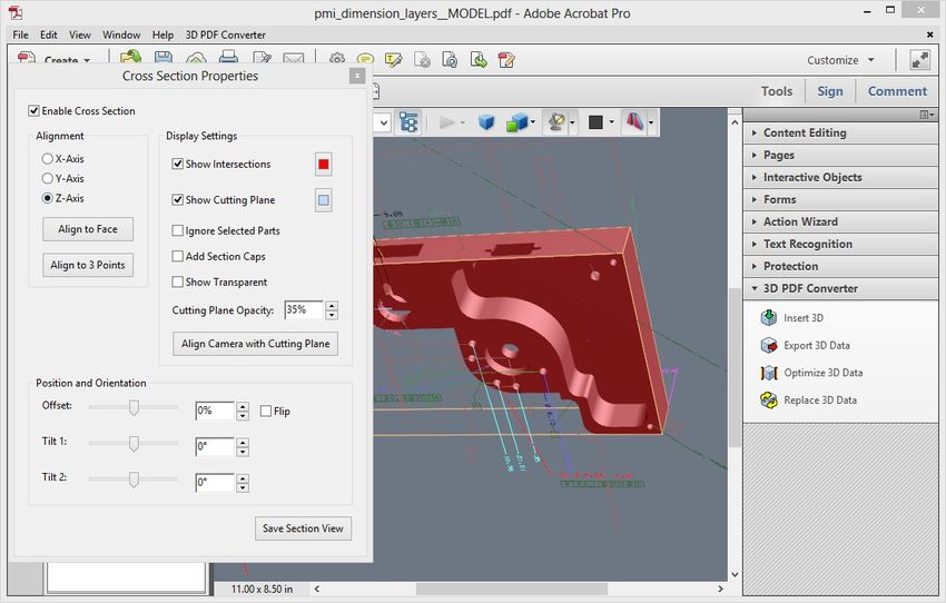
Table of Contents
 Chapter 1: Getting started .......................................................................................................................... 6
    Help ......................................................................................................................................................... 6
 Installation and activation .......................................................................................................................... 7
    Installation of Acrobat XI Pro and Acrobat Pro DC ................................................................................. 7
    System Requirements ............................................................................................................................. 7
    Installation of Tetra4D Converter ........................................................................................................... 7
 Running Tetra4D Converter ........................................................................................................................ 8
    License activation.................................................................................................................................... 8
 Chapter 2: Tetra4D Converter Overview .................................................................................................... 9
    Tetra4D Converter for Acrobat XI Pro .................................................................................................... 9
    Tetra4D Converter for Acrobat Pro DC ................................................................................................. 10
    Tetra4D Converter Tools Menu ............................................................................................................ 11
        Insert 3D............................................................................................................................................ 11
        Export 3D Data .................................................................................................................................. 11
        Optimize 3D Data .............................................................................................................................. 13
        Replace 3D Data ................................................................................................................................ 13
 Chapter 3: Converting 3D models............................................................................................................. 14
    Overview ............................................................................................................................................... 14
        More Help topics .............................................................................................................................. 14
    Convert 3D files into PDFs .................................................................................................................... 14
        Related Sections................................................................................................................................ 15
    Converting 3D files ................................................................................................................................ 15
    Create a PDF template for 3D files ....................................................................................................... 15
    Convert a 3D file using PRC settings ..................................................................................................... 16
        PRC B-rep (Solid) ............................................................................................................................... 16
        PRC B-rep + Tessellation ................................................................................................................... 16
        PRC Tessellation (Faceted) ................................................................................................................ 16
    Convert a 3D file using U3D settings .................................................................................................... 17
    About PRC and U3D conversion formats .............................................................................................. 17
        Benefits of PRC format...................................................................................................................... 17
        Benefits of U3D format ..................................................................................................................... 17

Tetra4D Converter 2019                                            Users Guide – V4.0                                                                              2
Chapter 4: Tetra4D Converter Conversion Settings ................................................................................. 18
    Tetra4D Converter Conversion Presets ................................................................................................ 19
    General Tab ........................................................................................................................................... 20
       Display ............................................................................................................................................... 20
       Default view ...................................................................................................................................... 21
       Navigation ......................................................................................................................................... 22
       Default Script .................................................................................................................................... 22
    Document Tab....................................................................................................................................... 22
    More Help topics .................................................................................................................................. 23
    Import Tab ............................................................................................................................................ 23
       Format Specific Data to Import......................................................................................................... 24
    Optimize Tab ......................................................................................................................................... 26
       3D Format in PDF .............................................................................................................................. 26
       Surface Triangulation ........................................................................................................................ 26
       PRC .................................................................................................................................................... 27
       U3D ................................................................................................................................................... 27
    Customize a conversion preset for a 3D file type ................................................................................. 28
       Convert large assemblies .................................................................................................................. 29
    Format specific reading options ........................................................................................................... 30
       STEP: Specific reading options .......................................................................................................... 30
 Chapter 5: Adding 3D models to PDFs....................................................................................................... 33
    Adding 3D Data ..................................................................................................................................... 33
       Create new pages from 3D models................................................................................................... 33
       Add a 3D model as a new page ......................................................................................................... 33
    Replacing 3D Data ................................................................................................................................. 33
       Replacing 3D in a PDF ....................................................................................................................... 33
    Managing 3D Data ................................................................................................................................ 34
    Move, delete, or resize the 3D canvas.................................................................................................. 34
    3D properties ........................................................................................................................................ 34
       Launch Settings Tab........................................................................................................................... 35
       3D Tab ............................................................................................................................................... 35
       Resources Tab ................................................................................................................................... 37

Tetra4D Converter 2019                                          Users Guide – V4.0                                                                              3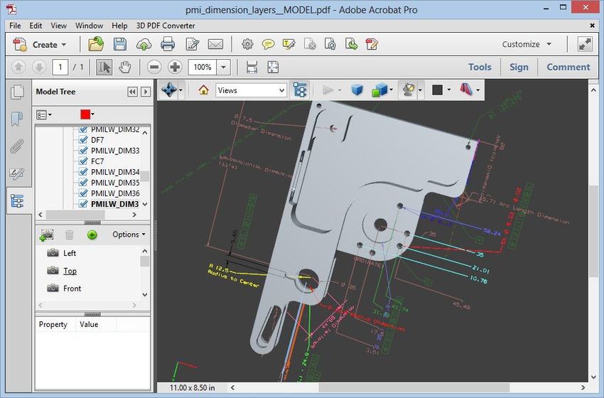
Chapter 6 .................................................................................................................................................. 39
Optimizing 3D Data ............................................................................................................................... 39
Chapter 7: Interacting with 3D models ..................................................................................................... 40
Displaying 3D models............................................................................................................................ 40
3D Toolbar Overview ............................................................................................................................ 40
3D navigation tools ........................................................................................................................... 41
3D toolbar view controls....................................................................................................................... 42
Examples of model rendering modes ................................................................................................... 43
Change rendering mode, lighting, projection, and background ....................................................... 44
Changing the appearance of the 3D model ...................................................................................... 44
Model Tree Overview ........................................................................................................................... 45
Hide, isolate, and change the appearance of parts ............................................................................... 46
View Product Manufacturing Information (PMI) .................................................................................. 47
Import Product Manufacturing Information (PMI)........................................................................... 48
Create Cross Sections........................................................................................................................ 49
Cross-Section Properties ................................................................................................................... 50
Measure 3D objects .............................................................................................................................. 51
Snap Enables options in the 3D Measurement Tool palette ................................................................ 52
Measurement Types options in the 3D Measurement Tool palette...................................................... 53
Units and markup options .................................................................................................................... 53
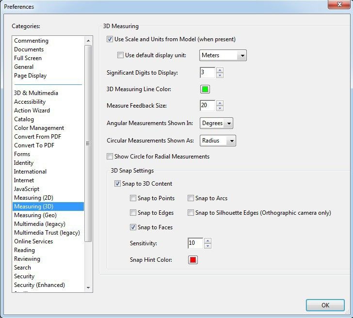
Measuring preferences ......................................................................................................................... 54
3D Measuring .................................................................................................................................... 55
3D Snap Settings ............................................................................................................................... 55
Change camera properties.................................................................................................................... 56
Set 3D views .......................................................................................................................................... 58
Create a custom view........................................................................................................................ 58
Display a view ................................................................................................................................... 59
Change the default view ................................................................................................................... 59
Add a 3D view to a bookmark or link ................................................................................................ 59
Delete a 3D view ............................................................................................................................... 60
3D Preferences...................................................................................................................................... 60
Renderer Options.............................................................................................................................. 61
Tetra4D Converter 2019 Users Guide – V4.0 4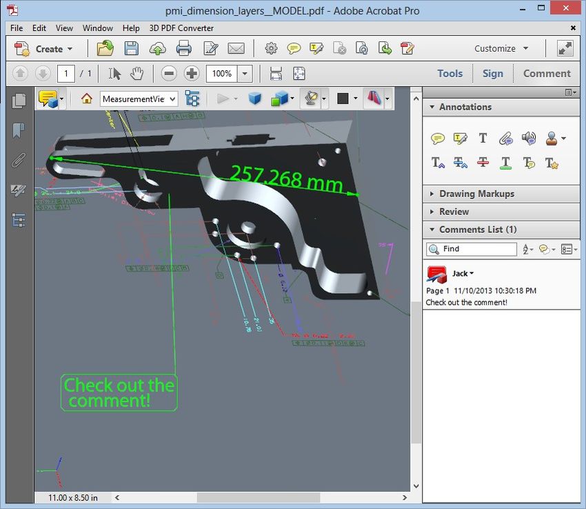
3D Tool Options ................................................................................................................................ 61
Auto Degrade Options ...................................................................................................................... 62
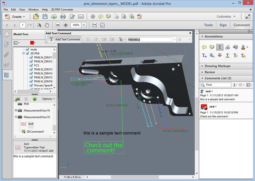
Comment on 3D designs ....................................................................................................................... 62
Add a 3D Comment to an object ...................................................................................................... 63
Add comments from the Comment & Markup toolbar .................................................................... 63
Convert 3D measurements to comments......................................................................................... 64
Display comments for a 3D object .................................................................................................... 64
Chapter 8: Exporting geometry from 3D models...................................................................................... 65
Export geometry ................................................................................................................................... 65
Format options for exporting geometry ................................................................................................ 65
IGES Settings ..................................................................................................................................... 65
Parasolid Settings .............................................................................................................................. 66
STEP Settings ..................................................................................................................................... 66
VRML Settings ................................................................................................................................... 66
STL Settings ....................................................................................................................................... 66
U3D Settings...................................................................................................................................... 67
PRC Settings ...................................................................................................................................... 67
X3D Settings ...................................................................................................................................... 67
3MF Settings ..................................................................................................................................... 67
JT Settings ......................................................................................................................................... 68
ACIS Settings ..................................................................................................................................... 68
FBX Settings ...................................................................................................................................... 68
OBJ Settings ...................................................................................................................................... 68
Chapter 9: Adding functionality to 3D designs with JavaScript ................................................................. 69
3D JavaScript Overview ......................................................................................................................... 69
Add a JavaScript to a PDF ...................................................................................................................... 69
Tetra4D Converter 2019 Users Guide – V4.0 5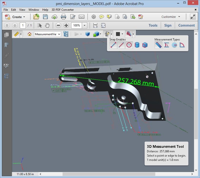
Chapter 1: Getting started
Before you begin working with Tetra4D Converter™, please take a few moments to read an overview
of the license activation process and the many resources available to you. You have access to
instructional videos, plug-ins, templates, user communities, seminars, tutorials, RSS feeds, and much
more.

Help
As part of your purchase, you are eligible for support of your installation of Tetra4D Converter via a
maintenance contract. Your maintenance contract also gives you access to new versions of Tetra4D
Converter as they are released. If you have questions about the status of your maintenance contract,
give us a shout.
For help with this and any other general support need that you have, please submit a support
request by going to http://www.tetra4d.com/support or by accessing your customer portal.
For support specific to Adobe Acrobat, please visit the Adobe Support website at:
http://helpx.adobe.com/support.html.
To download samples and start experimenting with Tetra4D Converter right away, please visit:
http://www.tetra4d.com/pdf-samples.
Also, please note that we have a YouTube channel. You can view various instructional videos on how
to use Tetra4D Converter as well as some of our other products here:
http://www.youtube.com/user/Tetra4D/videos.

Tetra4D Converter 2019                    Users Guide – V3.0                                         6
Installation and activation
Installation of Acrobat XI Pro and Acrobat Pro DC
Tetra4D Converter has been developed as an Add-in for Adobe® Acrobat® Pro and supports versions
XI and DC. As such, Acrobat XI Pro or Pro DC is required to be installed for Tetra4D Converter to
function.
A free trial of Acrobat Pro DC can be downloaded at:
https://www.acrobat.com/en_us/free-trial-download.html
Please refer https://helpx.adobe.com/acrobat.html for detailed instructions and troubleshooting
related to Acrobat Pro DC.

System Requirements
Please refer to the Tetra4D Converter installation guide by going to http://tetra4d.com/documentation
or by accessing your customer portal.

Installation of Tetra4D Converter
Please refer to the Tetra4D Converter installation guide by going to http://tetra4d.com/documentation
or by accessing your customer portal.

Tetra4D Converter 2019                   Users Guide – V3.0                                             7
Running Tetra4D Converter
To run Tetra4D Converter, please go to your start menu and launch Acrobat Pro. When you first
launch Acrobat Pro after installing Tetra4D Converter, you will see the following dialog box until your
license has been activated.
Tetra4D Converter starts automatically in a trial mode, with a 28 days duration.

   •   Select the Buy Now button to go to the Tetra4D web store to purchase licenses of the
       Tetra4D Converter.
   •   Select the Continue Trial button to run in trial mode. The Tetra4D Converter will run in trial
       mode for 28 days after installation.
   •   You should receive a serial number in an email from tetra4d.com when you purchase the
       Tetra4D Converter. To activate your license, select the I already have a serial number button
       and enter your serial number in the activation window.
If you are unsure what your license status is or just need help in general, please submit a support
request by going to http://www.tetra4d.com/support or by accessing your customer portal.

License activation
Please refer to the Tetra4D Converter installation guide by going to http://tetra4d.com/documentation
or by accessing your customer portal.

Tetra4D Converter 2019                    Users Guide – V3.0                                            8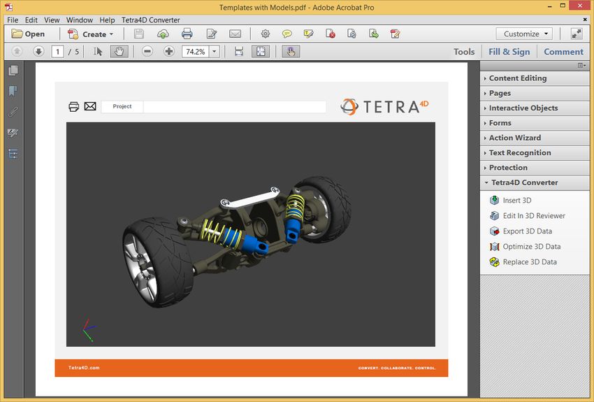
Chapter 2: Tetra4D Converter Overview
Tetra4D Converter allows you to create rich PDFs from supported 3D and CAD file formats and from
geospatially enabled PDFs. You can interact with 3D PDFs in several ways allowing you to rotate,
move, and measure parts and distances.
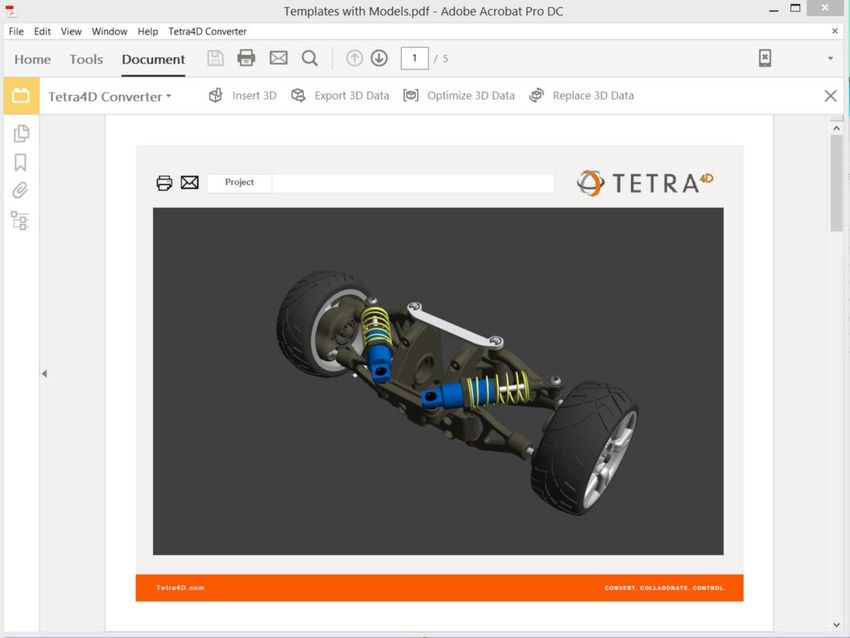
Tetra4D Converter for Acrobat XI Pro
Adobe Acrobat Pro XI Tetra4D Converter menu
Tetra4D Converter tools
Tetra4D Converter 2019 Users Guide – V3.0 9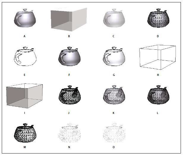
Tetra4D Converter for Acrobat Pro DC
         Adobe Acrobat Pro DC          Tetra4D Converter menu

                                                                Tetra4D Converter tools

Tetra4D Converter 2019          Users Guide – V3.0                                    10
Tetra4D Converter Tools Menu
• Acrobat XI Pro
• Acrobat Pro DC
Insert 3D
This allows 3D CAD data to be converted and inserted into a PDF Document. When selected, you
define the position and size of the 3D annotation frame, then select the 3D source file. The file is
then imported and placed within your PDF document, after which you can manipulate the 3D image
as you like.
For more information see “Chapter 3: Converting 3D Models”.
Export 3D Data
This allows you to export and save 3D Data from your PDF in another file format. Supported file
formats for exporting include:
File Format File Extension
ACIS .sat
IGES .igs, .iges
JT .jt
Parasolid .x_t
PRC .prc
STEP .stp, .step
Stereo Lithography (STL) .stl
U3D .u3d
VRML .vrml, .wrl
X3D .x3d
3MF .3mf
FBX .fbx
OBJ .obj
Tetra4D Converter 2019 Users Guide – V3.0 11Tetra4D Converter 2019 Users Guide – V3.0 12
In addition, you have the opportunity to specify certain exported attributes. For example, for IGES,
clicking on Settings in the Save File dialog box offers you the following choices:

For more information about exporting, see “Chapter 8: Exporting Geometry from 3D models”. Please
note that this functionality may change over time as file formats change and as Tetra4D Converter is
enhanced to support additional formats. Please see “U3D and PRC Formats” for more information.

Optimize 3D Data
Allows the 3D Data to be further optimized for file size and performance.
For more information see “Optimizing 3D Data”. Please note that this functionality may not be
available because of the format type. Please see “U3D and PRC Formats” for more information.

Replace 3D Data
Allows one 3D dataset to be easily replace with another.
For more information see “Replacing 3D Data”. Please note that this functionality may not be
available because of the format type. Please see “U3D and PRC Formats” for more information.

Tetra4D Converter 2019                     Users Guide – V3.0                                          13
Chapter 3: Converting 3D models
Overview
Adobe Acrobat Pro can consume and display data from a variety of different formats. When
combined with Tetra4D Converter, you extend this functionality to support many types of 3D
models. A list of all supported file formats appears in Acrobat’s Preferences dialog box (Select Edit ->
Preferences -> Convert to PDF).
Adobe® Acrobat® Pro with Tetra4D Converter can use a variety of file formats, including many types
of 3D models. A list of the supported file formats appears in the Preferences dialog box (select
Convert To PDF under Categories). For more information about the specific file formats supported at
this time, view our datasheet at http://www.tetra4d.com/tetra-4d-converter/.
You can import supported file formats directly into PDFs using the following methods:
Converting: This option starts with existing 3D CAD files and creates PDFs from them. This action is
accessible within Acrobat in a variety of ways.; using the File -> Create -> PDF From File, Right Click the
CAD file-> Convert to 3D PDF, Select CAD file-> drag-and-drop into Acrobat.
Adding with the “Insert 3D” tool: This option allows you to place a 3D model on an existing page in
any PDF.
Either of these methods provides options for representing the 3D model and preserving the original
structure of the model. For example, you can choose the level of detail, format, and compression.
If a 3D model is in a format that Acrobat doesn’t support, open the model in the application that it
was created in and export it in a format supported by Tetra4D Converter.

More Help topics
See “Tetra4D Converter conversion settings” for more information

Convert 3D files into PDFs
You can convert 3D and CAD files in supported formats to PDFs that have one or more pages. The
default preset works best for most types of conversion; however, you can change these settings or
select a different preset before or during the conversion. To view and/or edit your default conversion
settings before you convert a file, open the Acrobat Preferences dialog box. In Categories, select
Convert To PDF, select a file format, and click Edit Settings. You can also change this right before
your file converts in the Converter settings dialog box.
3D files are converted as either PRC or U3D data streams and then stored in the resulting PDF file.
The file format of the 3D file determines which entities you can import to the PDF.
If your Windows computer uses an integrated video adapter, make sure that your video driver is
relatively up to date to ensure that the 3D content renders correctly and as quickly as possible. You
can usually obtain updated video driver software from the website of your video card or computer
manufacturer.

Tetra4D Converter 2019                      Users Guide – V3.0                                           14
Related Sections
“About PRC and U3D conversion formats”
“Customize a conversion preset for a 3D file type”

Converting 3D files
   1. To create a simple PDF document based off of a single 3D file, within Acrobat choose File ->
      Create -> PDF From File… Select the 3D source file that you desire and click Open.
   2. To create a PDF document based off of multiple 3D files, within Acrobat choose File -> Create
      -> Combine Files into a Single PDF. This will bring up a dialog box that allows you to either
      drag and drop your 3D files or add them using the Add Files dropdown menu. Each 3D file will
      be displayed on a separate page or a PDF Portfolio. Refer to Acrobat help for more
      information about PDF Portfolios.
   3. In the Tetra4D Converter Conversion dialog box, select the preset or individual settings you
      want to use, and click OK.
   Note: From the desktop, you can also drag a 3D file into Acrobat XI Pro or Acrobat Pro DC (or onto the
   application icon) to create a single- page PDF file.

Create a PDF template for 3D files
To give 3D PDFs a consistent layout and structure, you can create a PDF template that contains a
placeholder for a 3D model. Create the template in any application as long as it has the ability to be
saved as a PDF file. After you create a template, select it in the Tetra4D Converter Conversion dialog
whenever you convert a 3D file to PDF.
   1. In an Office 2003 document, click the Save to PDF button on the PDF toolbar. In an Office
      2007/2010 document or newer, click the Create PDF button on the Acrobat ribbon.
   2. Open up the PDF in Acrobat XI Pro or Acrobat Pro DC.
   3. In the Tetra4D Converter tool area, choose Add 3D.
   4. Select any 3D CAD file. This step creates a placeholder for your 3D conversion.
To use this template when you convert a file, click the Document tab in the Tetra4D Converter
Conversion dialog box. If the template name is not displayed in the Template PDF section, click
Browse to find and select/open it.

Tetra4D Converter 2019                    Users Guide – V3.0                                           15
Convert a 3D file using PRC settings
Use PRC settings to create a PDF that contains Product Manufacturing Information (PMI), polygon
settings or tessellation, and geometry or b-rep (boundary representation). After you create the PDF,
you can export geometry to standard file formats that most CAD, CAM, and CAE applications read.
Within Acrobat choose File -> Create -> PDF From File… Select the 3D CAD file, and click Open.
1. In the Tetra4D Converter Conversion dialog box, click the Import tab.
2. To import Product Manufacturing Information (PMI) with the 3D model, select 3D PMI &
Views. You can import PMI from CATIA V5, I-DEAS, JT, NX (Unigraphics), Creo
(Pro/ENGINEER), and SolidWorks files. This option is available only if the model contains PMI.
3. To replace the fonts used in PMI, click Fonts, select Always Substitute, specify the font, and
click OK.
4. If you select Always Substitute, you remove any reference in the PDF to the font used for
PMI. If you leave Always Substitute unselected, Acrobat substitutes any missing fonts. If the
original fonts become available, they are used to display PMI.
PRC B-rep (Solid)
Retains only the geometry information of the 3D model. This option produces the smallest files, but
polygons must be regenerated each time the file is opened.
See “Exporting geometry from 3D models” for more information
PRC B-rep + Tessellation
Retains the geometry of the 3D geometry and any saved polygon settings. If the 3D model doesn’t
include polygon settings, they’re generated from the geometry during conversion.
PRC Tessellation (Faceted)
Retains the polygon settings of the 3D model or generates new polygons based on the geometry.
1. Select a level of detail. To set precise measurements, select either User Defined (for
visualization) or Controlled Precision (for STL printing), and then click Advanced.
2. (Optional) To apply compression, select a PRC compression option. If you plan to export
geometry, leave Compress B-rep to unselected, or set the value to 0.001 mm.
Note: Compressed PDFs are smaller but take longer to open than uncompressed PDFs. To save time,
compress only when you have to—after PDF conversion: Right-click the 3D model, and choose
Optimize. This option is available only in PDFs that were converted using PRC settings.
When you secure a 3D PDF that contains geometry, avoid settings that restrict editing and printing
the PDF. Otherwise, it disables the option to export geometry.
Tetra4D Converter 2019 Users Guide – V3.0 16Convert a 3D file using U3D settings
1. Within Acrobat choose File -> Create -> PDF From File…. Select the 3D CAD file, and click
Open.
2. In the Conversion dialog box, click the Optimize tab, and choose a U3D conversion setting
from the 3D Format In PDF menu:
U3D ECMA 3
Ensures compatibility with Acrobat 8.1 and later and Adobe Reader® 8.1 and later.
U3D ECMA 1 (Reader 7.0 Compatible)
Ensures compatibility with Acrobat 7.0 and later and Reader 7.0 and later.
3. Select a level of detail. To set precise measurements, select either User Defined (for
visualization) or Controlled Precision (for STL printing), and then click Advanced.
4. (Optional) For U3D ECMA 3 conversion, select Mesh Quality and specify a percentage.
5. Specify other options as needed and click OK.
About PRC and U3D conversion formats
When you create a PDF from a supported 3D file, the PDF stores 3D data as either PRC or U3D
(Universal 3D) format, depending on the settings you choose. Whether PRC or U3D settings are
available in the Tetra4D Converter Conversion dialog box depends on which 3D application created
the file you’re converting.
PRC is a 3D format that lets you create different representations of a 3D model. For example, you can
save only a visual representation that consists of polygons, or you can save the geometry that the
model is based on. You can apply compression during conversion to decrease file size, or afterward
in Acrobat Pro. By using PRC, you can create PDFs that are interoperable with Computer Aided
Manufacturing (CAM) and Computer Aided Engineering (CAE) applications.
U3D is an open standard format adopted by ECMA International used primarily for visualization and
publishing purposes. U3D settings are available for most CAD files created in digital content creation
applications. These settings are also available for most CAD files created in mechanical engineering
applications.
Benefits of PRC format
• Allows storage of large CAD files to PDFs that are a fraction of the original size.
• Supports post-conversion compression for faster loading.
• Can represent Product Manufacturing Information (PMI), also referred to as Geometric
Dimensioning and Tolerancing (GD&T) or Functional Tolerancing and Annotation (FT&A).
• Can retain geometry for reuse in CAD, CAM, and CAE applications.
Benefits of U3D format
• Supports animations.
Tetra4D Converter 2019 Users Guide – V3.0 17Chapter 4: Tetra4D Converter Conversion Settings
In the Conversion dialog box, you can specify settings for converting 3D models for PDFs on various
tabs. Or, choose a preset from the menu.
Note: The Acrobat Conversion dialog box does not appear if the “Don’t display dialog during
conversion” option at the bottom of this dialog box is selected.
Tetra4D Converter Conversion Settings dialog box
Tetra4D Converter 2019 Users Guide – V3.0 18Tetra4D Converter Conversion Presets
3D Conversion Settings Presets
• Default: Provides optimum settings for the selected file format by balancing quality with PDF
file size.
• Custom: Indicates that you’ve selected one or more individual settings. Click the plus sign (+)
to save your selections at a custom preset.
• Visualization/Small File: Produces the smallest file size possible by applying compression,
which may reduce image quality.
• Visualization/High Quality: Produces detailed, high-quality PDFs, but may increase file size.
• Collaboration: Produces high-quality, uncompressed PDFs.
• Publishing: Produces high-quality, compressed PDFs.
• Data Exchange: Preserves the exact geometry (or geometry compressed at 0.001 millimeter)
for reuse with CAE and CAM applications.
• U3D ECMA Standard Ed 3: Specifies U3D 3rd Edition format and 99% compression.
• U3D ECMA Standard Ed 1: Specifies U3D 0.0 format and no compression.
• Large File: Specifies settings to use for converting large assemblies
Tetra4D Converter 2019 Users Guide – V3.0 19General Tab
These settings determine how the imported 3D model is presented in Acrobat Pro. Unlike the settings
on the other tabs, General settings don’t affect the imported file itself.
Tetra4D Converter Conversion Settings General Tab
Note: Some of these settings can be changed after you import a file by using the options on the 3D
toolbar.
Display
• Default Background Color: Identifies the color behind the 3D model. Click the color swatch to
make changes.
• Default Lighting: Shows the lighting style to be used on the imported file.
Note: For best performance when manipulating 3D models, select the Headlamp option.
• Default Rendering Style: Shows the rendering style used for the imported model. Select a
different style from the menu, if needed.
• Default Animation Style: For models created with animation, this setting determines how
the animation runs in Acrobat.
Tetra4D Converter 2019 Users Guide – V3.0 20Default view
• Projection: Defines the projection mode used in the default view of the PDF document.
Note: The default view is the one used to create the 3D annotation poster image.
The choices are:
- Perspective,
- Orthographic.
• Orientation: Defines the orientation used for the default view.
Note: The default view is the one used to create the 3D annotation poster image.
Several preset options are proposed:
- Acrobat: This option is the default one. It corresponds to the acrobat orientation that has
been used for the previous versions of Tetra4D Converter.
o This preset orientation can’t be modified.
- CAD software: These options define orientations that correspond to the default orientations
of the CAD software.
o These preset orientations can’t be modified.
- Manage orientation: This option makes it possible to define other orientations and to save
them.
o When selecting “Manage orientation”, the following dialog is shown:
1. Define a new orientation name.
2. Select the vertical axis in the drop down list
o The vertical axis is the axis from the CAD file that will be vertical in the PDF
document
3. Define the Vertical Rotation value
o The first rotation is done around the vertical axis of the 3D annotation
4. Define the Horizontal Rotation value
o The second rotation is done around the horizontal axis of the 3D annotation
5. Click on the “+” icon to save the settings
Tetra4D Converter 2019 Users Guide – V3.0 21Navigation
• Add Default Views: Select this setting to change the imported views. An orthographic
projection (ortho) effectively removes a dimension, preserving the size ratio between objects
but giving the 3D model a less realistic appearance. Orthographic projection is useful for
viewing certain diagrams, such as 3D mathematical functions plotted on a graph. A
perspective projection offers a more realistic scene in which objects in the distance appear
smaller than objects of the same size in the foreground.
• Show 3D Toolbar By Default: Displays the 3D toolbar when the model is activated. When this
option is not selected, you can right- click the 3D image to view the 3D toolbar.
• Open Model Tree By Default: Displays the Model Tree when the 3D PDF file is opened.
Default Script
Specifies the JavaScript file that runs if a 3D model is enabled. If the 3D model you’re importing
doesn’t include embedded JavaScript, click Browse to specify the JavaScript file you want to run.
Document Tab
Use the Document settings to determine the layout of the page containing the 3D model, set up
read/write permissions for the file, and encrypt the converted file.
Tetra4D Converter Conversion Settings Document Tab
• Template PDF: Specifies an existing PDF file in which to place the 3D model. Click Browse to
select a PDF to use. Click clear to remove the template and set up the page using the Layout
options.
• Layout: Select Page Setup to change the margins, page size, and page orientation (portrait or
landscape) of the converted model.
• Security: Set an encryption level for the PDF, require a password to open it, and set editing
and printing permissions.
Tetra4D Converter 2019 Users Guide – V3.0 22More Help topics
Please refer to the Acrobat Pro Help guide at http://www.tetra4d.com/documentation for more
details on Security.
Import Tab
These settings determine what entities and information from the file that is under process will be
imported into the 3D PDF document.
Tetra4D Converter Conversion Settings Import Tab
Tetra4D Converter 2019 Users Guide – V3.0 23Format Specific Data to Import
Specify the types of information that you want to import into the 3D PDF document when reading
the native 3D CAD model or standard 3D file. The available options reflect the file format of your 3D
model.
Entities and information
• Solids: Specifies if solid objects are read.
• Surfaces: Specifies if surface objects are read.
• Wireframe: Specifies if wireframe entities are read.
• 3D PMI & Views: Specifies if PMIs and views are read.
• Attributes: Specifies if meta-data linked to the objects (parts) are read.
• Hidden objects: Specifies if the hidden entities are read.
• Construction & References: Specifies if construction & reference entities like planes and axes
are read.
• Active filter: Specifies what layers and filters are read.
• 3D/Drawing: Specifies if read information are 3D or 2D.
• Assembly view filtering: Specifies when an assembly is read if the native CAD views that are
defined in the components are taken into account. This option applies for CATIA V5 and
Autodesk Inventor formats.
• View filtering: Specifies what types of views are read or ignored.
The filters are:
o View name: Specifies what views are ignored or kept, based on the name of views.
The criteria is a string of characters that is searched in the view names.
o Read top assembly views only: Specifies if the views defined in the components of
the assembly are read or not. This setting applies to CATIA V5 and Inventor formats
only.
Specifics…
Click Specific to have the access to some reading options or features that are available only with the
file format currently under reading. The Specific option is proposed for the following CAD formats:
• Creo (Pro/ENGINEER),
• NX,
• STEP.
Note: Refer to STEP: Specific reading options to have detailed explanations about STEP validation
properties.
Tetra4D Converter 2019 Users Guide – V3.0 24Fonts…
Specifies how the PMIs are managed when the 3D PDF document is created:
• set up substitute fonts for the fonts in the original 3D file,
• Set up substitute color for the colors of the PMIs in the original 3D file,
• Set up a directory where to look for CAD proprietary fonts.
Tetra4D Converter Conversion Settings Import Tab: Fonts option
Assembly…
Click Assembly to define the directories to search parts that are not in the current folder. For large
assemblies in which the master file refers to many parts and subassemblies, some parts can be in
multiple directories.
Tetra4D Converter 2019 Users Guide – V3.0 25Optimize Tab
Adjust the Optimize settings to select the file format to convert 3D data to and the corresponding
compression.
Tetra4D Converter Conversion Settings Optimize Tab
3D Format in PDF
Choose between U3D and PRC conversion formats in the Format menu. The file format of your 3D
model determines which settings are available.
Surface Triangulation
Level of Detail
Specify the level of detail used to display the 3D model. Higher settings produce more accurate
results. Lower levels of detail are useful for quick visualization with reduced visual quality. Two
additional settings allow you to set specific height and angle values:
• User Defined: Use to produce good quality model rendering for visualization and 3D printers
• Controlled Precision: Use to create more accurate meshes for export to 3D printers.
Level of detail can only be set when you import a model. If you import a model with User Defined
tessellation, you must reimport the file to create the tessellation required for 3D printers.
When you select either User Defined or Controlled Precision, click Advanced to define the
triangulation parameters.
Tetra4D Converter 2019 Users Guide – V3.0 26Advanced
• Chord Height Ratio: Specifies the percentage of bounding box used to compute chord height.
Set a value from 50 through 10,000.
• Wireframe Chord Angle: Specifies the maximum angle between two contiguous segments of
wire edges for every face. The value must be from 10 through 40.
• Maximum Chord Height: Specifies the maximum distance, in millimeters, between surface
and tessellation.
• Minimal Triangle Angle: Specifies the angle between two contiguous segments of wire edges
for every face. The value must be between10 and 30.
• Binary File: Creates a binary version of the STL output file, which is smaller than the standard
ASCII STIL file.
PRC
• Compress B-rep To: The amount (in millimeters) of lossy compression applied to geometry.
For best results when exporting geometry, set the amount to 0.001 or leave this option
unselected.
Note: You can compress the geometry after you convert the 3D file to PDF by right-clicking the 3D
model and choosing Optimize PDF.
• Compress Tessellation: Applies lossy compression to polygons.
• Force Compute Tessellation: Reads the B-rep and computes the tessellation according to the
selected level of details criteria. Retains only tessellation data in the PDF document.
Note: This option applies for some CAD formats where a tessellation is stored in the native files (CATIA
V5 and SolidWorks). If not checked, the native tessellation is directly read, leading to a shorter reading
time, but ignoring the level of details.
U3D
• Mesh Quality: Controls the quality relative to the percentage of lossy compression applied to
the image files. Higher percentages indicate less compression and better image quality. A
setting of 100% applies no compression.
• Geometry Center Model at Origin: Translates the entire model so that the center of its
bounding box is at the origin [0,0,0] of the XYZ coordinate system.
Tetra4D Converter 2019 Users Guide – V3.0 27Customize a conversion preset for a 3D file type
You can create your own conversion presets for different types of 3D files, making it easy to reapply
all the individual options you use most often for a specific type of 3D file.
Presets are tied to the 3D format. For example, if you create a preset for CATIA V5 files, that preset
appears only when converting CATIA V5 files. You can create multiple presets for each 3D format.
When you convert or capture a 3D file, the most recently used preset for that file type is selected.
1. Choose Edit > Preferences, and then choose “Convert to PDF” under Categories.
2. In the central panel of the Preferences, select the 3D file format to which the custom preset
will apply, and then click Edit Settings.
Note: If you select a non-3D file type, the Edit Settings button may not be available or it may open a
different dialog box.
3. Using the four tabs in the Conversion dialog box, specify the settings you want to include in
the preset.
4. Above the tabs, in Description, type something that will help you to recognize the preset,
such as its intended purpose or parameters.
5. Click the Add Preset icon.
6. Type a name for the preset, and click OK.
7. Click OK to close the Tetra4D Converter Conversion dialog box, and, if necessary, click OK to
close the Preferences dialog box.
Note: You can delete a custom preset by reopening the Tetra4D Converter Conversion dialog box,
selecting the preset from the menu, and then clicking the Minus Preset button.
Tetra4D Converter 2019 Users Guide – V3.0 28Convert large assemblies Converting large assemblies with numerous unique components to PDF can be both time-consuming and memory- intensive. For best results, create a tessellated representation of the assembly using PRC conversion settings. If the CAD file includes saved tessellation entities, Tetra4D Converter uses these entities instead of creating new ones. 1. Choose File -> Create PDF -> From File -> Select the 3D file or part. 2. In the 3D PD Converter Conversion dialog box, click the Import tab. 3. Click Assembly to select the appropriate file path for part files, and click OK. 4. Click the Optimize tab and choose PRC Tessellation (Faceted) from the Format menu. 5. From the Level of Detail menu, select Medium. Select any other options, and then click OK. Note: For you to complete this task, PRC settings must be available on the Optimize tab of the Tetra4D Converter Conversion dialog box. Tetra4D Converter 2019 Users Guide – V3.0 29
Format specific reading options
STEP: Specific reading options
The STEP AP 242 standard supports “validation properties”. The “validation properties “ are
additional meta-data added in the STEP file, meant to give the ability to validate a CAD data
translation process (Conversion of CAD files from one CAD system into a different one, using STEP as
intermediate format). The validation properties apply to parts and assemblies, geometry, PMIs and
views.
This chapter describes how the validation properties already existing in a STEP file can be exploited
during the conversion of this STEP file into a 3D PDF document.
   1. Choose File -> Create PDF -> From File -> Select the STEP file.
   2. In the 3D PD Converter Conversion dialog box, click the Import tab.
   3. Click Specific to access the Validation properties related options.
   4. Click Read Validation properties in order to read the validation properties that are present in
      the STEP file
       Note: The read validation properties can be accessed in the Log file.
   5. Click Compute validation properties in order to compute the validation properties using the
      information from the 3D annotation
       Note: after the conversion of the STEP file into a 3D PDF document, validation properties will be
       calculated based on the 3D PDF information and then compared with the read validation
       properties. The validation properties are compared with the Geometry and PMI tolerances that
       are defined in this panel.
   6. Use the Geometry and PMI sub-panel to define the tolerances that will be used when
      comparing the read validation properties and the computed one
   7. Click (optional) Add Result To Name in order to add the results of the comparison to the
      names of the entities in the 3D annotation data tree
   8. Click on OK to validate the options and continue the conversion process.

Tetra4D Converter 2019                     Users Guide – V3.0                                              30
STEP Reader specific options (Validation properties feature) Tetra4D Converter 2019 Users Guide – V3.0 31
Access to validation properties
The validation properties can be accessed after the conversion of the STEP file into a PDF document
as follows:
     1. In the Model Tree
        Note: If validation properties are only read (Compute validation properties not checked), the
        validation properties are presented in the Model Tree like other meta-data.

or
     2. Choose Tetra4D Converter (top menu) -> Last log file
        Note: If validation properties have been computed (Compute validation properties checked), the
        validation properties are presented in the Model Tree and also in the LOG file.

Tetra4D Converter 2019                     Users Guide – V3.0                                           32
Chapter 5: Adding 3D models to PDFs
Adding 3D Data
Create new pages from 3D models
You can use 3D models in supported file formats as the basis of new PDFs, or you can bring them
directly into existing PDFs. For many supported formats, you can do any of these in Acrobat Pro.
Add a 3D model as a new page
1. Open a PDF, and if Acrobat XI Pro, choose Tools > Pages > More Insert Options > Insert Blank
Pages
If Acrobat Pro DC, choose Tools > Organize Pages > Insert > Blank Page
2. Indicate where you want to place the inserted page in the document, and click OK.
3. Select Tools > Tetra4D Converter > Add 3D
4. Indicate where you want to place the 3D annotation by dragging to create a rectangle on the
page.
5. In the Select File dialog box, choose the file type from the Files of Type menu. Select the
supported 3D file you want to open, and then click Select.
6. In the Tetra4D Converter Conversion dialog box, select the preset or individual settings that
you want to use, and then click OK.
Replacing 3D Data
Replacing 3D in a PDF
1. In the Select File dialog box, choose the file type from the Files of Type menu. Select the
supported 3D file you want to open, and then click Open.
2. In the Tetra4D Converter Conversion dialog box, select the preset or individual settings that
you want to use and then click OK. Replace 3D models to a PDF page.
You can use the 3D tool to place a 3D file on a page of a PDF. During this process, you can select how
the model is displayed and the lighting, navigation, and display settings (like those found on the 3D
toolbar), and change conversion settings.
After you place a 3D file, you can adjust the area or canvas in which the 3D model appears, edit the
presentation properties for the 3D toolbar and content, and create additional views.
Tetra4D Converter 2019 Users Guide – V3.0 33Managing 3D Data
Move, delete, or resize the 3D canvas
1. If Acrobat Pro XI, choose Tools -> Interactive Objects- > Select Object Tool.
If Acrobat Pro DC, choose Tools -> Rich Media- > Select Object.
Note: Be careful not to confuse the Select Object tool with the basic Select tool. Use the Select Object
tool to adjust a 3D canvas.
2. Select the 3D canvas and change it as needed:
• To move the canvas, drag it to a new location on the page.
• To delete the canvas (and the 3D model), select it and press Delete.
• To resize the canvas, drag the frame corners. The 3D content stays proportional within the
adjusted frame.
3D properties
View 3D properties by right-clicking on the model and select Properties.
Edit 3D Window
Tetra4D Converter 2019 Users Guide – V3.0 34Launch Settings Tab
Activation Settings
• Enable When: Specifies when the 3D model is activated. When the 3D model is enabled, you
can interact with it by using the 3D navigation tools, for example.
• Disable When: Determines how the 3D model can be deactivated. When a 3D model is
disabled, the 2D preview image or poster appears in the canvas.
• Playback Style: Enables you to display the 3D model in a floating window outside the page. If
you select Play Content in Floating Window, you can select the size of the window (in pixels)
from the Height and Width menus.
Appearance
• Border Width: Select to create a border around the 3D object.
• Transparent Background: Removes any background color.
Poster Image
• Poster Image: To replace the default view of the 3D model when it isn’t activated, select a
poster image option. Click Browse to find the image you want.
3D Tab
The options on the 3D tab determine how the 3D model is presented. Unlike the settings on the other
tabs, 3D settings do not affect the imported file itself.
3D tab of Edit 3D Window
Tetra4D Converter 2019 Users Guide – V3.0 35The options on the 3D tab are the same as the options on the 3D toolbar except for the following:
Default Display Settings
• Animation Style: For models created with animation, this setting determines how the
animation runs in Acrobat.
Navigation
• Add Default Views: Allows you to use different model views. An orthographic projection
(ortho) effectively removes a dimension, preserving the size ratio between objects but giving
the 3D model a less realistic appearance. Orthographic projection is especially useful for
viewing certain diagrams, such as 3D mathematical functions plotted on a graph. A
perspective projection offers a more realistic scene in which objects in the distance appear
smaller than objects of the same size in the foreground.
• Retain Views, Comments and Scripts: For models that have views, comments or scripts
associated to them, it is possible to remove these default attributes during import.
• Show Toolbar: Displays the 3D toolbar along with the image. When this option is not
selected, you can right-click the 3D image to view the 3D toolbar.
• Open Model Tree: Displays the model tree toolbar along with the image.
Script
Specifies the JavaScript file that runs if a 3D model is enabled. Click Browse to add a JavaScript file to
the PDF.
Tetra4D Converter 2019 Users Guide – V3.0 36You can also read