Data Traffic Modeling in RPAS/UAV Networks with Different Architectures - MDPI
←
→
Page content transcription
If your browser does not render page correctly, please read the page content below
Article
Data Traffic Modeling in RPAS/UAV Networks with
Different Architectures
Andrii Grekhov 1 , Vasyl Kondratiuk 2 and Svitlana Ilnytska 2,3, *

                                          1   Department of Air Navigation Systems, National Aviation University, 03058 Kyiv, Ukraine;
                                              grekhovam@gmail.com
                                          2   Research and Training Center “Aerospace Center”, National Aviation University, 03058 Kyiv, Ukraine;
                                              kon_vm@ukr.net
                                          3   Institute of Laser and Optoelectronics Intelligent Manufacturing, Wenzhou University,
                                              Wenzhou 325035, China
                                          *   Correspondence: ilnytskasv84@gmail.com; Tel.: +380-979-477-517

                                          Abstract: Deploying of Fifth Generation and Beyond Fifth Generation (5G/B5G) wireless networks
                                          will require wider coverage, flexible connectivity, low latency, support for a large number of user
                                          devices, and more bandwidth. This article explores the paradigm that Remotely Piloted Air Systems
                                          (RPASs) or Unmanned Aerial Vehicles (UAVs) are integrated as a communication platform with
                                          cellular networks using radio access. It is important to know the possibilities and ways of such
                                          integration for effective interaction with RPASs. This paper studies the issues of ensuring the
                                          required Quality of Service (QoS) during heavy traffic and the choice of necessary data transmission
                                          modes for this. Models of RPAS communication channels with different architectures were created.
                                          The relationships between models’ performance and traffic parameters were obtained using the
                                          NetCracker Professional 4.1 software. The dependencies of the Average Utilization (AU) on the

                                   Transaction Size (TS) were analyzed. The effects of different bandwidths and the Bit Error Rate (BER)
                                          were studied. The traffic characteristics in all models were compared.
Citation: Grekhov, A.; Kondratiuk,
V.; Ilnytska, S. Data Traffic Modeling
                                          Keywords: remotely piloted air systems (RPAS); unmanned aerial vehicles (UAVs); 5G/B5G; data
in RPAS/UAV Networks with
Different Architectures. Modelling
                                          traffic; transaction size; average utilization; BER; bandwidth
2021, 2, 210–223. https://doi.org/
10.3390/modelling2020011

Academic Editor: Franco Cicirelli         1. Introduction
                                                Remotely Piloted Air Systems (RPASs) are playing an increasingly important role in
Received: 8 March 2021                    civilian, community, and military purposes. The standards body 3rd Generation Partner-
Accepted: 26 March 2021
                                          ship Project (3GPP) is monitoring research on seamless integration of RPASs into Fifth
Published: 28 March 2021
                                          Generation and Beyond Fifth Generation (5G/B5G) cellular networks with an aim to im-
                                          prove them. RPASs can be used as wireless access points or relay nodes to increase cellular
Publisher’s Note: MDPI stays neutral
                                          terrestrial coverage, as well as for surveillance purposes with greater coverage compared
with regard to jurisdictional claims in
                                          to conventional fixed sensor nodes. The flexible spatial network architecture and mobility
published maps and institutional affil-
                                          of RPASs bring great benefits to 5G/B5G cellular systems when integrated.
iations.
                                                At present, it is very important to develop new structures for communication, pro-
                                          cessing and transmission of information in real time to support communication systems of
                                          RPASs/Unmanned Aerial Vehicles (UAVs) with high data transfer rates, helping terrestrial
                                          cellular communications in future wireless cellular networks. Therefore, the number of
Copyright: © 2021 by the authors.         publications devoted to these issues is growing. In recent years, books have been published:
Licensee MDPI, Basel, Switzerland.
                                          On RPAS/UAV networks and communications [1], wireless communications and network-
This article is an open access article
                                          ing for UAV [2], UAV communications for 5G and beyond [3], and UAV applications over
distributed under the terms and
                                          cellular networks for 5G and beyond [4]. Reviews and tutorials are devoted: To wireless
conditions of the Creative Commons
                                          communications with UAV [5], UAV cellular communications [6], 5G network availability
Attribution (CC BY) license (https://
                                          for operation with drones [7], cellular-connected UAVs [8], UAVs for wireless networks [9],
creativecommons.org/licenses/by/
4.0/).
                                          and UAV communications for 5G and beyond [10].

Modelling 2021, 2, 210–223. https://doi.org/10.3390/modelling2020011                                      https://www.mdpi.com/journal/modelling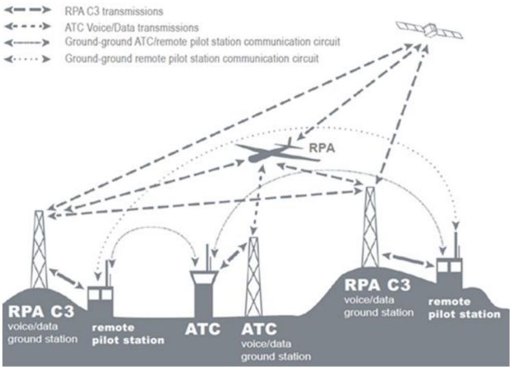
Modelling 2021, 2                                                                                              211

                          In this article, we study a RPAS/UAV-enabled Radio Access Networks (RAN) where
                    the RPAS/UAV is used as an airborne platform supporting communications for terrestrial
                    users, including relaying data from the base station to other RPASs/UAVs and terrestrial
                    users, downlink data transmission to terrestrial users, and collecting uplink data. This
                    multi-mode aerial communication platform is most attractive for a practical RAN with
                    different user requirements for the received data. For the RANs under consideration,
                    four models with different architectures are used, which are of practical interest. In the
                    first model, the base station controls the RPAS within the line of sight and communicates
                    through it with the users of the cellular network. In the second model, the base station
                    communicates with the cellular network via two RPASs to investigate the problem of
                    increasing coverage. The third model is used to study the traffic ramification and operation
                    with a large number of users. The fourth model is the closest to real conditions and contains
                    a complex architecture with the largest number of drones and ground users. The main
                    contributions of this paper are summarized as follows.
                          First, we offer original models as communication platforms for RPASs/UAVs with
                    cellular networks in various operating conditions, for which the characteristics of data
                    traffic in communication channels have been calculated for the first time.
                          Secondly, due to the complexity of the research problem for the designed models,
                    we propose an effective approach based on simulation modeling. The term “simulation”
                    means the calculation of the characteristics of a model, changing over time, by reproducing
                    the flow of this process on a computer using the equations of its mathematical model.
                          Third, for various architectures of communication channels, the results were obtained
                    and compared data transmission quality. From this point of view, the work can be con-
                    sidered as the development of theoretical methods for predicting the behavior of RPAS
                    communication channels in critical conditions.
                          Fourth, the practical value of the results is that using the obtained dependencies, you
                    can predict the channel’s behavior when the transaction size, channel bandwidth and bit
                    error rate change.
                          The rest of this article is organized as follows. Section 3 presents a research method
                    and algorithms for calculating traffic parameters. Section 4 describes the proposed models
                    and parameters of communication channels. Numerical results are presented in Section 5.
                    At the end of the article, the results are discussed in Section 6 and conclusions are given in
                    Section 7.

                    2. Related Works
                         The articles below consider technologies and applications of UAVs in cellular networks,
                    prospective RAN with UAVs, reliable communication for aerial vehicles over cellular
                    networks, and other important issues.
                         The article [11] analyzes UAV cellular communication and valuates the performance
                    of the downlink command and control channel when supported by either: A traditional
                    cellular network serving one user per transmission time interval, or a multi-user massive
                    Multiple Input Multiple Output (MIMO) network exploiting spatial multiplexing.
                         A RAN with a UAV acting as an aerial platform for communication with ground
                    users in the modes of data collection, data transmission, or relaying is considered in [12].
                    Iterative design algorithms of the UAV flight trajectory are proposed there.
                         A single cell cellular network, several cellular users and several UAVs that upload
                    their collected data to a base station are investigated in [13]. The UAV with a high Signal-to-
                    Noise Ratio (SNR) for the User-Infrastructure (U2I) channel downloads the collected data
                    directly to the base station, and the UAV with a low SNR for the U2I channel transmits the
                    data to the nearest UAV through the U2U backbone to ensure required Quality of Service
                    (QoS). The distribution of subchannels and the problem of optimizing the speed of the
                    UAV to maximize the total bandwidth of the uplink are formulated.
                         The network architecture of Distributed and Multi-layer UAVs (DAMUs) has been
                    presented for 5G/B wireless communication [14]. DAMU architecture due to hierarchical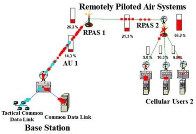
Modelling 2021, 2                                                                                             212

                    flexibility can be reconfigured for a specific deployment and application scenario, taking
                    into account key technical factors. A numerical analysis of the attenuation introduced by
                    typical meteorological conditions is carried out in this paper.
                         Drone Assisted Vehicular Networks (DAVNs) for the efficient integration of commu-
                    nication and networking technologies for drones and connected vehicles are presented
                    in [15]. A comprehensive DAVN architecture is proposed and it is demonstrated that the
                    performance of automotive networks can be significantly improved with the proposed
                    architecture.
                         An overview of the Long-Term Evolution (LTE) connectivity for UAVs at low altitude
                    is presented in [16]. Typical requirements and characteristics of airborne communication
                    are determined, the different propagation conditions for UAVs and mobiles on the ground
                    are emphasized, and the results of LTE connection modeling for UAVs are presented.
                         To ensure collaboration between UAVs and terrestrial users, two solutions have been
                    proposed to mitigate interference in existing LTE networks: Interference suppression and
                    antenna beam selection [17]. It is shown that each of solutions can provide up to 30%
                    increase in throughput and more than 99% of radio communication.
                         A path planning scheme taking into account interference for a network of UAVs
                    connected to cellular communication is proposed in [18]. A deep reinforcement learning
                    algorithm, based on Echo State Network (ESN) cells, is proposed to achieve a trade-off
                    between maximizing energy efficiency, reducing wireless latency and interference in the
                    terrestrial network. Each UAV uses the ESN to determine its optimal path, transmit power,
                    and cell association vector at different locations along its path.
                         Various communication architectures of the Future Flying Ad-Hoc Network (FANET),
                    including existing wireless technologies, are discussed in [19]. A hybrid wireless communi-
                    cation scheme is proposed to take advantage of the 802.11 high data rate and 802.15.1 low
                    power features. The proposed scheme significantly reduces communication costs and im-
                    proves network performance in terms of bandwidth and latency. The results of modeling
                    using the Optimized Network Engineering Tool (OPNET) are presented, which additionally
                    confirm the effectiveness of our proposed scheme.
                         The Internet of Things (IoT) requires high-performance two-way communication
                    between UAVs and their ground pilots/users using a cellular network [20]. An important
                    question is whether an existing cellular network designed for terrestrial users can also
                    effectively cover new UAV users in three-dimensional (3D) space for both uplink and
                    downlink. In practice, there are problems of terrestrial communications interference and a
                    non-uniform three-dimensional antenna gain pattern of a terrestrial base station. The article
                    presents a new 3D model of the system, taking into account UAV users, which offers an
                    analytical basis for determining the characteristics of their 3D uplink/downlink coverage.
                    A 3D analysis of the coverage was carried out taking into account the key parameters of
                    the system, such as the cell load factor, the tilt of the ground base station antenna, the UAV
                    height and the antenna beam width.
                         Potential 5G beneficiaries and network use are considered in [21]. Three main use
                    cases are considered: Vehicle-to-Vehicle communications, drones, and healthcare. The
                    challenges and disadvantages of current cellular technologies have been investigated and
                    highlighted in relation to these use cases, and ways to overcome these disadvantages in 5G
                    networks have been identified.
                         UAVs as a component of the IoT can provide sensing and communications in the air
                    due to their advantages in mobility and flexibility. However, the cellular QoS between the
                    UAV and the base station cannot be guaranteed when the UAVs are at the edge of a cell
                    or are experiencing deep fading. The article [22] considers the non-cooperative cellular
                    Internet of the UAV and proposes a joint data transfer protocol, in which the UAV can
                    download sensor data using the UAV relay to provide a better quality of communication
                    service for sensing tasks. The design of the trajectory and control of radio resources that
                    support the joint cellular Internet of the UAV are considered.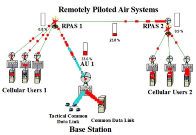
Modelling 2021, 3, FOR PEER REVIEW 4
Modelling 2021, 2 213
service for sensing tasks. The design of the trajectory and control of radio resources that
support the joint cellular Internet of the UAV are considered.
The
The RPAS/UAV communication requirements
RPAS/UAV communication requirementsmust mustbe beassessed
assessedininthe
thecontext
context
of of
an
an
AirAir Traffic
Traffic Control
Control (ATC)
(ATC) function
function [23] (Figure
[23] (Figure 1). Modeling
1). Modeling of channels
of channels for UAVfor UAV
commu-
communication over cellular
nication over cellular networks networks
has beenhasconsidered
been considered in a number
in a number of works,
of works, sincesince
UAV
UAV communication is an emerging and underexplored field. Accurate
communication is an emerging and underexplored field. Accurate channel parameters are channel parameters
are critical
critical to optimizing
to optimizing performance
performance and designing
and designing effective
effective UAV communications.
UAV communications. Models
Models
of path of path
loss andloss and shadowing
shadowing indicatorsindicators for achannel
for a radio radio channel
betweenbetween
UAVs and UAVs and
cellular
cellular
networks networks
are givenarein
given
[24].in
It [24]. It is shown
is shown that thethat the exponent
exponent of pathoflosses
path losses decreases
decreases as the
as the UAV
UAV moves moves upward,
upward, approaching
approaching propagation
propagation in free
in free space
space forfor horizontal
horizontal distancesof
distances
of up to tens of kilometers at an UAV height
up to tens of kilometers at an UAV height of about 100 m.of about 100 m.
Figure1.1.International
Figure International Civil
Civil Aviation
Aviation Organization
Organization (ICAO)
(ICAO) aeronautical
aeronautical Remotely
Remotely Piloted
Piloted Air
Air System
System (RPAS) communication
(RPAS) communication links [23]. links [23].
Anoverview
An overviewof ofthethemeasurement
measurementmethodsmethodsproposed
proposedfor formodeling
modelingUAV UAVchannels
channels
using low-altitude platforms, as well as attempts to determine the
using low-altitude platforms, as well as attempts to determine the channel characteristics,channel characteristics,
isisgiven
giveninin[25].
[25].The
Thereview
reviewalsoalsodiscusses
discussesapproaches
approachesto tomodeling
modelingUAV UAVchannels
channelsfromfromaa
modernpoint
modern pointofofview.
view.
AAnew
newCoordinate
CoordinateMultipoint
Multipoint(CoMP)
(CoMP)basedbasednetwork
networkarchitecture
architecturefor forUAV-assisted
UAV-assisted
wireless communications
wireless communications is is proposed in [26]. The Thehigh highmobility
mobilityofofthe theUAV UAVisisusedusedto
toachieve
achieve effective multi-user
effective multi-user communication
communication with
with several
several UAVs
UAVs andandto to
reduce
reduce interfer-
inter-
ence. TheThe
ference. placement
placement and and
movement
movementof theofUAV is optimized
the UAV is optimizedusing the theory
using the of random
theory of
random
matrices. matrices.
AAnew
newstructure
structurefor foraaUAV
UAVnetwork
networkwithwiththethepossibility
possibilityofofmass massaccess,
access,supported
supported
byby Non-Orthogonal
Non-Orthogonal Multiple Access Access (NOMA),
(NOMA), isisproposed
proposedinin[27]. [27].The The performance
performance as-
assessment
sessment ofof UAVnetworks
UAV networks with
with NOMA
NOMA is carried
is carried out,out,
usingusing stochastic
stochastic geometry
geometry to
to sim-
simulate
ulate thethe position
position of UAVs
of UAVs andand ground
ground users.
users. TheThe joint
joint design
design of the
of the trajectory
trajectory andandthe
the power distribution for static NOMA users based on a simplified
power distribution for static NOMA users based on a simplified 2D model of a UAV 2D model of a flying
UAV
flying at aaltitude
at a fixed fixed altitude is investigated.
is investigated. The problem
The problem of UAVof UAV placement
placement is solvedisusing
solved using
machine
machine
learninglearning
methods,methods,
when ground when users
ground areusers are in roaming,
in roaming, and the and UAVs theare
UAVsableareto able to
accord-
accordingly
ingly change change their position
their position in dimensions.
in three three dimensions.
AAsecured
securedUAV-assisted
UAV-assistedheterogeneous
heterogeneousnetworknetworkenvironment
environmentand andseamless
seamlessInternet
Internet
protocol
protocol prototype is proposed in [28]. UAVs are controlled over the Internettotoremove
prototype is proposed in [28]. UAVs are controlled over the Internet remove
communication
communication barriers
barriers overover long
longdistances
distancesand and improve
improve remote
remote sensing.
sensing. In new
In the the new
tech-
technology,
nology, the the
pilotpilot
can can control
control the UAV
the UAV through
through secure secure communication
communication with an with
endandevice
end
device without any information about network architectures, types
without any information about network architectures, types of network address transla- of network address
translation, and version
tion, and version of the of the Internet
Internet protocol.
protocol. Network Network
traversaltraversal with mobility
with mobility offers offers
secure
secure communications for UAVs over the public
communications for UAVs over the public network infrastructure.network infrastructure.
An effective technology to improve wireless coverage for remote and disaster-affected
areas is UAV radio access, which will be key for providing improved and sustainable cov-
erage in heterogeneous 5G cellular networks. Paper [29] studied edge caching for multiple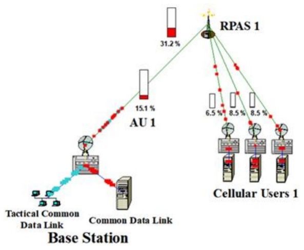
Modelling 2021, 2                                                                                                                    214

                    UAV-enabled radio access networks (UAV-RANs) and investigated the improvement in
                    overall spectral efficiency (SE) through efficient edge caching. UAV base stations may not
                    serve directly nearby users, but serve users based on requested content. Based on the SE
                    analysis achieved by the content-oriented UAV-RAN, a hybrid caching strategy is proposed
                    for further improvement the SE.
                          RPAS communication channels based on IEEE 802.11a, 802.11b, and 802.16 and LTE
                    standards are modeled in our works [30–34].
                          The articles considered above do not contain quantitative information on the impact
                    of traffic parameters on the operation of RPAS/UAV communication channels. It has not
                    been investigated how quantitatively the channel load can change with an increase in the
                    duration of transactions. How does the bandwidth affect the channel load at the given
                    traffic parameters? How does the increase in bit errors affect? There are no answers to
                    these questions in the literature.

                    3. Calculation Method
                             The NetCracker Professional 4.1 software [35] was chosen for traffic modeling in pro-
                    posed models (Figure 2). It uses an analytical simulator based on mathematical equations
                    to predict network behavior. The essence of the applied algorithm is as follows.
                             Let us denote the internal characteristics of the communication channel, which are
                    calculated at the time tk , as V 1 (tk ), . . . , Vn (tk ); external characteristics at the same moment
                    of time influencing them as W 1 (tk ), . . . , Wr (tk ), and the average rate of change of internal
                    characteristics in the time interval [tk , tk + 1] as Fi (tk , V 1 (tk ), . . . , Vn (tk ), W 1 (tk ) . . . Wr (tk )),
                    i = 1 . . . n. By specifying the values of the internal and external characteristics at the
                    moment tk , it is possible to calculate the values of the internal characteristics at the moment
                    (tk + 1). To do this, the segment [t0 , T] is divided into P parts by the points t0 , t1 , . . . ,
                    tk , . . . , tP = T. If the values of internal characteristics at time t0 and average rates of the
                    internal characteristics change on each segment [tk , tk + 1] are known, then using the
                    following relations it is possible calculating the values of internal characteristics for all tk ,
                    k = 1, . . . , P:

                                    Vi (tk + 1) = Vi (tk ) + ∆tFi (tk , V 1 (tk ), . . . , Vn (tk ), W 1 (tk ), . . . , Wr (tk )),    (1)

                    where i = 1, n; k = 0, 1, . . . , P − 1. We modeled such internal characteristics of communica-
                    tion channels as Average Utilization (AU), Travel Time (TT), and the number of dropped
                    packets. Transaction Size (TS), Time Between Transactions (TBT), Bit Error Rate (BER),
                    channel bandwidth, and packet failure probability were chosen as external characteristics
                    that influenced the mentioned internal characteristics. If we consider the functions Y1 (t),
                    . . . , Yn (t) as continuous and having derivatives, then to describe the process, the equations
                    of the following form are used

                                                      dVi /dt = Fi (t, V 1 , . . . , Vn , W 1 , . . . , Wr ),                         (2)

                    where i = 1, . . . , n. Here, the functions Fi (t, V 1 , . . . , Vn , W 1 , . . . , Wr ) represent the
                    “instantaneous” rates of change of the corresponding internal characteristics.
                         To calculate the parameters of the RPAS communication channel, it is necessary to
                    specify the statistical distribution laws for the lengths of transmitted packets ω(x) and the
                    time intervals (TBT) between them ω(t). In the proposed models, the Const probability
                    distribution law was used: ω(x) = Const and ω(t) = Const. Then the average length of
                    transmitted packets and the average time interval between two neighboring packets are
                    found by the Formulas (3) and (4) correspondently.

                                                                              Z∞
                                                                     TS =          xω ( x )dx.                                        (3)
                                                                             −∞
Modelling 2021, 2 215
Z∞
TBT = tω (t)dt. (4)
−∞
The average utilization of the communication channel is given by the formula:
AU = TS/TBT = TS/µ, (5)
where µ = 1/TBT is the packet transmission rate over the communication channel. The
utilization of the communication channel depends both on the size of the transmitted
packets and on the intensity of their generation. If the value of the AU parameter is greater
than the maximum data transmission rate of the communication channel, then some of the
transmitted packets will be lost with the probability:
AUlink
P = 1− . (6)
AU
The average packet travel time through the communication channel is determined by
the formula:
TS
TT = . (7)
AUlink
4. Models
In our previous works [32,33] models of communication channels “Base Station-to-
RPAS” and “Base Station-to-Satellite-to-RPAS” were built on the basis of 3GPP Wideband
Code Division Multiple Access (WCDMA) Standard. Using the MATLAB software, quan-
titative characteristics of the channels were obtained taking into account the Multipath
Rayleigh Fading, the nonlinearity of the satellite transponder, various antenna diameters,
and RPAS speeds.
In this work, within the framework of the RPAS-assisted cellular communication
paradigm, we first developed models with different architectures for simulating the traffic
of Base Station (BS) data exchange with user cellular networks using RPAS.
The BS can be ground or air with two-way traffic both in the control channel and in
the payload channel in all models. Flying RPASs have access to cellular infrastructure from
the sky. This paradigm allows the establishment of reliable wireless communications with
ground cell sites. It is assumed that the BS will not simultaneously work with terrestrial
users within the radio Line of Sight (LoS).
Flying RPASs should have antennas with radiation patterns that provide three-
dimensional coverage for communications with the BS, ground cellular network and
other RPASs. Integration of RPASs into a cellular network must provide the necessary QoS,
coverage and data transfer rates of the existing cellular network. The proposed model
architectures, due to the dynamic mobility and movement of the RPAS, provide many
advantages to the existing ground communication system. The flying BS or relay can be
provided as required upon request of 5G/B5G cellular systems, which is an attractive
operational solution in emergencies, disasters, and search and rescue operations. The
RPAS team reliably communicates directly with each other to monitor autonomous flight
behavior and prevent collisions in swarms. This architecture is illustrated by the example
of Models 2, 3, and 4 (Figure 2).Modelling 2021, 2 216
Modelling 2021, 3, FOR PEER REVIEW 7
(a) (b)
(c) (d)
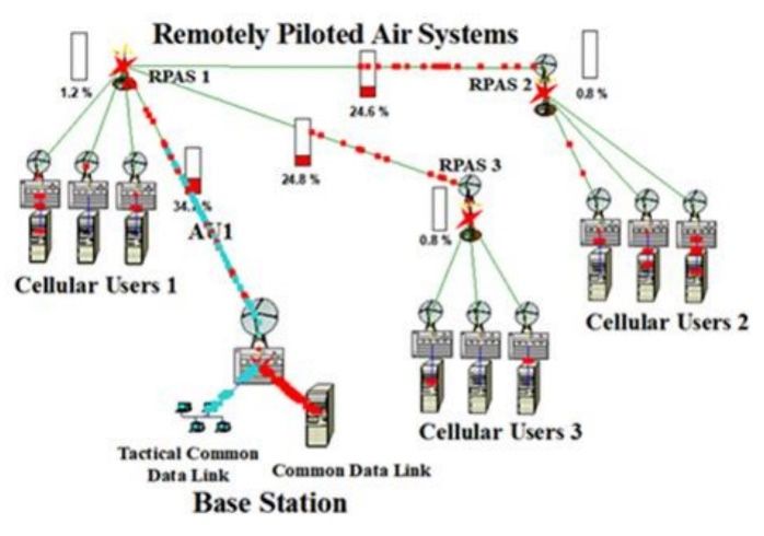
Figure 2. Architecture of models: (a) Model 1; (b) Model 2; (c) Model 3; and (d) Model 4.
Figure 2. Architecture of models: (a) Model 1; (b) Model 2; (c) Model 3; and (d) Model 4.
The
The models’
models’ architecture was based
architecture was based on
on ICAO
ICAO document
document [23][23] and
and included
included BS,
BS, RPASs,
RPASs,
and CellularUsers
and Cellular Users(CUs).
(CUs). AllAll models
models (Figure
(Figure 2) were
2) were designed
designed usingusing Professional
Professional Net-
NetCracker
Cracker 4.1 software
4.1 software [35] and
[35] and their their parameters
parameters are given are given1.in Table 1.
in Table
In Model 11 “BS-RPAS1-CU3”,
In Model “BS-RPAS1-CU3”,the theBSBScontrols
controlsRPAS1
RPAS1 inin LoS,
LoS, andand through
through it com-
it commu-
municates with the cellular network, represented by three users. In all
nicates with the cellular network, represented by three users. In all models, networksmodels, networks
containing
containing 1,1, 3,
3, 5,
5, and
and 77 users
users were
were considered,
considered, but
but in this work,
in this work, for
for simplicity,
simplicity, data
data are
are
given for only
only three
threeusers
usersforforeach
eachRPAS,
RPAS,which
whichdoes
doesnotnot limit
limit inin
anyany
wayway
thethe generality
generality of
of
thethe consideration.
consideration.
In Model 2 “BS-RPAS1-RPAS2-CU3”,
“BS-RPAS1-RPAS2-CU3”, the the BS
BS communicates
communicates with the cellular network
through two RPASs, which increases coverage and reveals the impact of the second RPAS
on data traffic.
Model 3 “BS-RPAS1-CU3-RPAS2-CU3”
“BS-RPAS1-CU3-RPAS2-CU3” adds users to RPAS1 RPAS1 for simulation of traffic
ramification to work with more users and increase increase the
the BS
BS coverage.
coverage.
Model 44 “BS-RPAS1-CU3-RPAS2-CU3-RPAS3-CU3”
“BS-RPAS1-CU3-RPAS2-CU3-RPAS3-CU3” considers
considers anan even
even more
more com-
complex
architecture
plex with an
architecture addition
with of RPAS3
an addition and CUand
of RPAS3 3, which
CU 3,further
whichincreases the BS coverage
further increases the BS
and increases
coverage and the load on
increases RPAS1
the (Figure
load on RPAS13). (Figure
All wireless connections
3). All of the BS, RPASs
wireless connections of theand
BS,
CUs are selected to be 10 km.
RPASs and CUs are selected to be 10 km.Modelling 2021, 2 217
Table 1. Parameters of Models.
Parameters →
Bandwidth (Mbps) Length (m) BER (%)
Model Elements ↓
Model 1: “BS-RPAS1-CU3”
Base Station
Tactical Data (TD) Workgroup 10 - -
Common Data (CD) Server 10 - -
TD—Switch link 10 1 0
CD—Switch link 10 1 0
Switch 1000 - -
Switch—Antenna link 44.736 10 0
Antenna 1000 - -
BS—RPAS 1 wireless link 2.048–44.736 105 0–0.05
RPAS 1 1000 - -
RPAS 1—CUs 1 wireless links 44.736 105 0
CUs 1
Antenna 1000 - -
Antenna—Switch link 44.736 10 0
Switch 1000 - -
Switch—Server link 10 1 0
Server 10 - -
Model 2: “BS-RPAS1-RPAS2-CU3” (in addition to Model 1)
RPAS 1—RPAS 2 wireless link 44.736 105 0
Antenna 1000 - -
RPAS 2 1000 - -
Model 3: “BS-RPAS1-CU3-RPAS2-CU3” (in addition to Model 2)
RPAS1—CUs 1 wireless links 44.736 105 0
CUs 1
Model 4: “BS-RPAS1-CU3-RPAS2-CU3-RPAS3-CU3” (in addition to Model 3)
RPAS 1—RPAS 3 wireless link 44.736 105 0
RPAS 3—CUs 3 wireless links 44.736 105 0
CUs 3
The wireless architecture of connecting the BS to the RPAS1 and each of the RPAS to the
CU results in more reliable LoS channels. In addition, our models incorporate RPASs space
diversity to reduce mutual interferences. In reality, there are effects such as fading, shading
and loss along the way that should be considered. Only the free-space channel model
lacks fading and shading effects and is suitable for rural areas where the LoS assumption
is valid for high-altitude RPAS and ground stations. However, in urban environments,
low-altitude RPAS can detect channels other than LoS. Therefore, it is necessary to look for
ways to properly match the propagation conditions taking into account the propagation
loss in space.
Mentioned effects can lead to a decrease in the data transmission rate and an increase
in the number of bit errors in messages. For a quantitative assessment of the consequences
of this, we simulated data transmission with different rates (Figure 4) and the number of
bit errors (Figure 5) for all models.
For RPAS data transmission, it is necessary to organize Command, Control, and
Communication (C3) data traffic (Figure 1) in accordance with the ICAO circular [23]. The
C3 data traffic consists of a Tactical Data channel (Command and Control) for RPAS flight
control and a Common Data channel for transmitting payload data. Command and Control
communication without payload data refers to time-critical control and safety commands
for maintaining flights and includes navigation, waypoint updates, telemetry reports, and
Air Traffic Control communications. The reliability requirement for this is less than 10−6 bit
error rate. Payload transmission refers to all information of the RPAS/UAV mission andModelling 2021, 3, FOR PEER REVIEW 9
Modelling 2021, 2 commands for maintaining flights and includes navigation, waypoint updates, telemetry 218
reports, and Air Traffic Control communications. The reliability requirement for this is
less than 10−6 bit error rate. Payload transmission refers to all information of the
RPAS/UAV mission and can include the transmission of data from users of the cellular
can include
network, the transmission
remote multisensor ofdata
data (radar
from users
data,ofoptical,
the cellular network,
infrared remote
systems, multisensor
etc.), and trans-
data (radar data, optical, infrared systems, etc.), and transmit real-time
mit real-time video at a high data rate in the surveillance operation. video at a high data
rate in the surveillance
Traffic operation.
with File Transfer Protocol (FTP) profile for Tactical Data (TS = 100 Kbits and
Traffic with File Transfer Protocol
TBT = 1 s with Const distribution laws) (FTP)
and profile for Tactical
Local Area Network Data (TS LAN)
(inter = 100 Kbits
profileand
for
TBT = 1 s with Const distribution laws) and Local Area Network (inter LAN) profile for
Common Data (TS and TBT with Const distribution laws, TBT = 1 s) has been defined for
Common Data (TS and TBT with Const distribution laws, TBT = 1 s) has been defined for
the designed models with topology according to Figure 2. Command, Control, and Com-
the designed models with topology according to Figure 2. Command, Control, and Com-
munication traffic is carried out as two-way communication. RPAS/UAV communication
munication traffic is carried out as two-way communication. RPAS/UAV communication
requirements were selected in accordance with the cellular communications [8] and ICAO
requirements were selected in accordance with the cellular communications [8] and ICAO
requirements [36].
requirements [36].
5. Results
5. Results
This section
This section presents
presents the
the calculated
calculated dependencies
dependencies of of the
the average
average utilization
utilization for
for the
the
“BS-RPAS1” link (AU1) on the TS parameter, the link bandwidth
“BS-RPAS1” link (AU1) on the TS parameter, the link bandwidth and the BER. The average and the BER. The aver-
age channel
channel utilization
utilization refers
refers to the
to the average
average traffic
traffic on aongiven
a given channel
channel as aaspercentage
a percentage of of
a
a total channel bandwidth. The channel bandwidth is the amount
total channel bandwidth. The channel bandwidth is the amount of information in bits of information in bits
per second
per second that that aachannel
channel cancanpass
passoveroveraacertain
certaintime
timeperiod.
period.In Inaddition
additionto tothe
theaverage
average
utilization, such
utilization, such parameters
parameters as as message
message travel
travel time,
time, the
the number
numberof ofdropped
droppedpackets,
packets,andand
the average
the averageworkload
workloadwere werealso
also calculated.
calculated. For
For simplicity,
simplicity, thisthis article
article provides
provides datadata for
for the
the average utilization
average utilization only. only.
ItIt is
is necessary
necessary toto find
find how
how thethe architecture
architectureof ofthe
themodels
modelsisisrelated
relatedtotothe
the quantitative
quantitative
characteristics of
characteristics of traffic.
traffic. How
How cancan adding
adding ofof one
one oror two
two newnew RPASs
RPASschange
changetraffic?
traffic? How
How
does traffic
does traffic change
change across
across models
models with
with different
different architectures
architectures in in response
response to toincreasing
increasing
transactionsizes?
transaction sizes? At
At what
what size
size of
of transactions
transactionsisisthe
thechannel
channelclosed?
closed? Does
Doesthis
thishappen
happenfor for
the same
the same valuesvalues in
in different
differentarchitectures?
architectures?
Figure
Figure 3. Dependencies of
3. Dependencies of Average
AverageUtilization
Utilization(AU)
(AU)for
forAU1
AU1link
linkononCommon
Common Data
Data Transaction
Transaction
Size (TS) (Tactical Data— File Transfer Protocol (FTP), TS =
Size (TS) (Tactical Data—File Transfer Protocol (FTP), TS = 100 Kbits, Time Between Transactions
Between Transactions
(TBT)
(TBT)== 11 s,
s, Const
Const law;
law; Common Data— LocalArea
CommonData—Local AreaNetwork
Network(inter LAN),
(inter LAN),TBT
TBT= =1 1s, s,Const
Constlaw; and
law;
andError
Bit Bit Error
Rate Rate
(BER)(BER) = 0%).
= 0%).
All
All distances
distances were
were considered
considered toto be
be equal
equal to
to 10 km, as indicated in Table
Table.1.1.The
Thegoal
goal
was
was to
to find out the
find out the average
averageAU1AU1link
linkutilization
utilizationfor
fordifferent
differentmodels.
models. Figure
Figure 3 shows
3 shows the
the dependencies
dependencies of AU
of the the AU parameters
parameters for“BS-RPAS1”
for the the “BS-RPAS1” channels
channels onsize
on the theof
size
theof the
Com-
Common
mon DataData transactions
transactions for for different
different models.
models. AtAtthethesame
sametime,
time, Tactical
Tactical Data
Data traffic
traffic
remained constant with TS = 100 Kbits. Messages of both types of traffic are sent every
second. The nature of the dependencies is approximately the same for all models. The AU
values practically do not change for TS parameter values from 10 bits to 10 Kbit, increasing
only for TS = 100 Kbits. The increase in the AU parameter occurs as the transition fromModelling 2021, 3, FOR PEER REVIEW 10
remained constant with TS = 100 Kbits. Messages of both types of traffic are sent every
Modelling 2021, 2 219
second. The nature of the dependencies is approximately the same for all models. The AU
values practically do not change for TS parameter values from 10 bits to 10 Kbit, increasing
only for TS = 100 Kbits. The increase in the AU parameter occurs as the transition from
Model 11 to
Model to Model
Model 4, 4, that
that is,
is, as
as the
the architecture
architecture of of the
the models
models becomes
becomes more
more complex.
complex.
When TS
When TS>> 100
100 Kbits,
Kbits, the
the channel
channel isisclosed
closedforforall
allmodels.
models.The Thetransmission
transmissionofofCommon
Common
Data becomes
Data becomes impossible
impossible in in the
the case
case of
of the
theselected
selected transmission
transmission conditions
conditions for
for Tactical
Tactical
Data traffic.
Data traffic. The
The results
results for
for Models
Models 11 and
and 22 are
are practically
practically the
the same
same (for example, ≈ ≈ 2.5
2.5%%
and ≈
and ≈ 2.7%,
2.7 %,respectively,
respectively,for forTCTC==1000
1000bits),
bits),but
butwith
withincreasing
increasingcomplexity
complexityof
ofthethemodel
model
architecture, the
architecture, AU parameter becomes equal to ≈≈5.7
the AU 5.7% % (Model 3) and ≈≈7.5 % (Model
7.5% (Model 4).
Theincrease
The increasein inthe
theload
loadofofthe
theAU1
AU1channel
channelduring
duringthethetransition
transition from
from Model
Model 1 to1 to Model
Model 4
occurs
4 occursalmost
almost three times.
three times.
Figure 4. Dependencies
Figure 4. Dependencies of
of AU
AU on
on AU1
AU1 link
link bandwidth
bandwidth (Tactical
(TacticalData—FTP,
Data—FTP,TS TS==11Kbits,
Kbits,TBT
TBT==11s,
Const law; Common Data—inter LAN, TS = 10 Kbits, TBT = 1 s, Const law; and BER = 0%).
s, Const law; Common Data—inter LAN, TS = 10 Kbits, TBT = 1 s, Const law; and BER = 0%).
The established requirements for the cellular communication of the RPASs/UAVs [8,36]
The established
correspond to the datarequirements
transfer rate over for thethecellular
Command communication
and Control of the RPASs/UAVs
channel ~ 100 Kbps
[8,36]
and thecorrespond
payload channel to the~ 50 data transfer
Mbps. That rate
is why over
when theobtaining
Command the and Control channel
dependencies shown
~ 100
in Kbps
Figure 3, and the payload
for Tactical Datachannel ~ 50 Mbps.
the parameters TS That
= 100isKbits,
why when TBT =obtaining
1 s were the depend-
chosen. At
encies
the same shown
time,inthe Figure
data 3, for Tactical
transfer rate orData the parameters
bandwidth for Tactical TS =and100 Common
Kbits, TBTData = 1 sinwereall
chosen. At
network the same
branches was time, the data
T3 (44.736 transfer
Mbps), rate or bandwidth
as indicated in Table 1.for Tactical and
However, Common
in reality, the
data
Datatransfer rate may
in all network decreasewas
branches dueT3 to(44.736
different reasons.
Mbps), As the bandwidth
as indicated in Table 1. decreases,
However, lessin
and less the
reality, information
data transfer can pass
rate through
may decrease the channel
due toper unit of reasons.
different time. How Ascantheabandwidth
change in
data transfer
decreases, lessrate
and affect
less network
information loadcanin models with different
pass through the channel architectures?
per unit of With time.what
How
data
can atransfer
changerates in datamodels
transfercanrate
operate?
affectThe answers
network loadtointhese
models questions are contained
with different architec- in
Figure 4.
tures? With what data transfer rates models can operate? The answers to these questions
The dependencies
are contained in Figure 4. of the AU parameter on AU1 link bandwidth for all models
(FigureThe 2)dependencies
are shown in Figure of the AU 4. The bandwidth
parameter ranged
on AU1 link from 6 Mbps to
bandwidth forE3all(34.368
models Mbps)
(Fig-
and T3are
ure 2) (44.736
shown Mbps).
in FigureDependencies
4. The bandwidth are given for TS
ranged from = 16 Kbits
Mbps for to E3Tactical
(34.368DataMbps) traffic
and
and TS = 10Mbps).
T3 (44.736 Kbits for Common Data
Dependencies traffic.forThis
are given TS =is1due
Kbits to for
theTactical
fact thatData
it is traffic
necessary
and to TS
simultaneously observe the data transmission in all models,
= 10 Kbits for Common Data traffic. This is due to the fact that it is necessary to simulta-which is difficult to ensure
at large values
neously observe of the
the data
TS parameters
transmission for in
bothall channels.
models, whichThe AU parameter
is difficult increases
to ensure at with
large
decreasing the bandwidth and at 6 Mbps bandwidth reaches
values of the TS parameters for both channels. The AU parameter increases with decreas- ≈ 70% for Model 4, ≈ 50% for
Model 3, ≈ 23% for Model 2, and ≈ 19% for Model 1. For
ing the bandwidth and at 6 Mbps bandwidth reaches ≈ 70 % for Model 4, ≈ 50 % for T3 and E3 bandwidths AU values
for all models
Model 3, ≈ 23 % dofornot exceed
Model ≈10%.
2, and ≈ 19However,
% for Model as the bandwidth
1. For T3 and E3decreases,
bandwidths a significant
AU values
increase in the AU parameter is observed, which makes it practically
for all models do not exceed ≈ 10 %. However, as the bandwidth decreases, a significant impossible to transfer
data for Models 3 and 5 at the bandwidth below ≈ 10 Mbps.
increase in the AU parameter is observed, which makes it practically impossible to The results for Models 1 and
trans- 2
are very close and show the data transfer capability of such
fer data for Models 3 and 5 at the bandwidth below ≈ 10 Mbps. The results for Models 1 models over a wide range of
data rates.Modelling 2021, 3, FOR PEER REVIEW 11
Modelling 2021, 2 220
and 2 are very close and show the data transfer capability of such models over a wide
range of data rates.
Figure 5. Dependencies of AU on AU1 link BER (Tactical
Figure 5. (Tactical Data—FTP,
Data—FTP,TS TS==11Kbits,
Kbits,TBT
TBT== 11 s,s,Const
law; Common Data—inter LAN, TS = 10 Kbits, TBT = 1 s, Const law; and BER = 0%).
Const law; Common Data—inter LAN, TS = 10 Kbits, TBT = 1 s, Const law; and BER = 0%).
The −6
The BER
BER measured
measured afterafterForward
ForwardError
ErrorCorrection
Correction(FEC)
(FEC)should
shouldbebeless
lessthan
than1010−6 in
in
accordance
accordance with
with ICAOICAO requirements
requirements [36,37].
[36,37]. Figure
Figure 55 shows
shows the
the dependencies
dependencies of of the
the AU
AU
parameter
parameter on on the
the BER
BER for
for the
the “BS-RPAS1”
“BS-RPAS1” channels
channels of
ofall
allmodels.
models. The
The dependencies
dependencies are are
given for TS = 1 Kbits for Tactical Data traffic and TS = 10 Kbits for
given for TS = 1 Kbits for Tactical Data traffic and TS = 10 Kbits for Common Common Data traffic
Data as
traffic
in the case of
as in the case Figure 4.
of −Figure The BER value for channels without additional error correction
4. The BER value for channels without additional error correction is
usually − 4
10 10–10 6
is usually −4–10−6.. Bit
Bit distortion
distortion occurs
occurs both
both due
due to
to the
the presence
presence of
of noise
noise in
in the
the channel
channel
and due to the distortion of the waveform in channels with limited bandwidth. The BER
and due to the distortion of the waveform in channels−with limited bandwidth. The BER
value of 0.01% in Figure 5 corresponds to a value of 10 −44 . The data presented in Figure 5
value of 0.01% in Figure 5 corresponds to a value of 10 . The data presented in Figure 5
indicate a high sensitivity of channels to bit errors. As in previous cases, the results for
indicate a high sensitivity of channels to bit errors. As in previous cases, the results for
Models 1 and 2 are very close. The results indicate that it is necessary to use effective error
Models 1 and 2 are very close. The results indicate that it is necessary to use effective error
correction techniques in the case of complex networks (Models 3 and 4).
correction techniques in the case of complex networks (Models 3 and 4).
6. Discussion
6. Discussion
The RPAS in practical use often requires communication that goes beyond visual line
TheMobile
of sight. RPAS in practicaloffer
networks use the
often requires communication
opportunity to use the RPASthat goes beyond
outside of visualvisual line
LoS with
of sight. Mobile networks offer the opportunity
wide area, high speed, and secure wireless connections. to use the RPAS outside of visual LoS with
wideThis
area,work
high isspeed,
devotedandtosecure wireless connections.
the development of theoretical methods for predicting the
Thisofwork
behavior RPASiscommunication
devoted to the channels
developmentwhenof theoretical
integrating methods
with cellularfor predicting
networks. the
In our
behavior works
previous of RPAS communication
([30–34] and references channels when
therein), weintegrating
studied thewith cellular networks.
transmission of messages In
our previous works ([30–34] and references therein), we studied the
using RPASs/UAVs in direct and indirect visibility, through terrestrial networks without transmission of mes-
sages
and using
with the RPASs/UAVs
use of satellites.inThedirect and indirect
research was based visibility, through terrestrial
on the simulation networks
of communication
channels using Matlab and NetCracker software. IEEE 802.11a, 802.11b, and 802.16of
without and with the use of satellites. The research was based on the simulation com-
[30,31]
munication
and channels[32,33]
LTE Standards usinghave
Matlab beenand NetCracker
used software.
in the various IEEEThe
models. 802.11a,
main802.11b,
purposeand of
802.16studies
these [30,31]wasandto LTE Standards
obtain [32,33]characteristics
quantitative have been used of in the various
RPAS models. The
communication main
channels
purpose
and of these
to develop studiesfor
methods was to obtain the
calculating quantitative
parameters characteristics
of communicationof RPAS communica-
channels.
tion The
channels and
articles to develop
considered in methods for calculating
the introduction the parameters
demonstrate of communication
the achievements in the field
channels.
of RPASs/UAVs communications. However, we could not find quantitative information
on theThe articles considered
influence in the introduction
of traffic parameters demonstrate
on the exchange of datathebetween
achievements
the basein the field
station
of RPASs/UAVs
and users of cellular communications.
networks through However, we could not
the RPAS/UAV. Howfinddoes
quantitative information
the transactions size
affect
on thechannel
influence loading?
of trafficHow does theon
parameters bandwidth
the exchangeaffect
ofthe
datachannel
between utilization
the base for the
station
given trafficofparameters?
and users What and
cellular networks how affects
through the qualityHow
the RPAS/UAV. of service, namely
does the the increase
transactions size
in the number
affect channel of bit errors?
loading? HowTheredoesare theno answers toaffect
bandwidth suchthequestions
channelinutilization
the literature,
for theso
this article considers three main aspects: The different architecture of channel models, anModelling 2021, 2 221
algorithm for calculating the parameters of communication channels, and the application
of the results to assess the quality of data transmission.
From data of Figure 3 (dependencies on the transaction size) it follows that in a wide
range of the TS parameter (from 10 bits to 10 Kbits), the AU values practically do not
change for all models. At the same time, the complexity of the network architecture leads
to an increase in the network load by more than three times.
Figure 4 (dependencies on the bandwidth) shows that for reliable data transmission
you should use a bandwidth not lower than T3 (44.736 Mbps) for all models. In this case
the network load will not exceed ≈ 10%. In complex networks, efficient data transmission
is practically impossible at bandwidths below 10 Mbps due to a significant increase in
network utilization.
At BER = 0% (Figure 5), the AU values for Models 1 and 2 coincide (≈2.7%), for
Model 3 is of the order of ≈5.4%, and for Model 4 it reaches ≈7.2%. As the BER increases,
the differences between the models increase, and the situation is most unfavorable for
Model 4. Figure 5 is relevant for understanding the conditions for achieving the required
level of QoS in the network.
In addition to the above models, we considered Model 1 (Figure 2), containing N users
of the cellular network. It was important to analyze this in order to understand what to
expect from a significant increase in users’ number and how this increases the load in the
RPAS communication channel. Model 1 was considered for the cases of N = 1, 3, 5, 7, and
10 users, for which values similar to those shown in the Figures 3–5 have been calculated.
At the same time, all links bandwidth, in contrast to the data of Table 1, were taken to be
equal to 10 Mbps (which is almost 5 times less), and the FTP traffic in the Control and
Command channel was 10 Kbits (which is 10 times more than discussed above). This choice
of parameters was interesting for analyzing the behavior of “insufficiently fast” networks
with significant traffic volumes. For brevity, these data are not presented in full here. Let
us just say that, for example, doubling the number of users from N = 5 to N = 10 leads to a
twofold increase in the parameter AU for the link “BS-RPAS1” (TS = 1000 bits and other
parameters similar to those discussed above).
In general, our research shows that using the obtained data on traffic characteristics
(Figures 3–5), it is possible to choose the right operating conditions and successfully
exchange data between the base station and users of remote cellular networks using
RPAS/UAV integration.
In the future, we will expand our research to RPAS satellite radio access networks,
coordinated data transfers between ground base stations and predicting channel behavior
in critical conditions. In our next work, we will present the results obtained for models
containing instead of RPAS1 (Figure 2) the low-orbit satellite Iridium.
NetCracker software tools allow you to create a network, carry out the necessary
simulation experiments, determine the final characteristics, change the topology and
modify the network equipment for further improvement and development. The capabilities
of the NetCracker software for predicting traffic parameters were tested in our work [38].
The obtained dependencies of the message transit time (1.4–1.9 s) on the number of satellites
and aircraft were experimentally confirmed by Aireon [39], which provided air traffic
surveillance data to its partners. Tracking more than 10,000 aircraft with ADS-B 1090
Extended Squitter receivers for Iridium NEXT satellites, the system delivered data to air
traffic control centers with a delay of less than 1.5 s [40].
7. Conclusions
The presented research is devoted to obtaining quantitative characteristics of RPAS/
UAV traffic parameters for radio access technology to cellular networks. Models of
RPAS/UAV integration are based on the ICAO recommendations. Base station data trans-
mission channels have different architectures, for which the RPAS/UAV traffic parameters
were first obtained. The dependencies of the average channel utilization on the transaction
size, the effect of different bandwidth, and the effect of the bit error rate were obtainedModelling 2021, 2 222
and analyzed. A quantitative comparison of traffic characteristics in models with different
topologies was carried out.
It was discovered that the AU values practically do not change for the considered
models when varying the TS parameter (from 10 bits to 10 Kbits), which means messages
of bigger size can be transmitted with the same efficiency. However, for reliable data
transmission the one should use a bandwidth not lower than T3 (44.736 Mbps) for all
models (to avoid network load higher than 10%). At zero BER all considered models has
AU values less than 8%. However, with the BER increase, the situation becomes the most
unfavorable for Model 4. The obtained data allow us to judge about the provision of the
required quality of service with heavy traffic and about the choice of the necessary data
transmission modes for this. With appropriate communication strategies, an RPAS/UAV
platform can provide a viable relay or broadcast node for high-bandwidth communications.
Author Contributions: Conceptualization, A.G., V.K. and S.I.; methodology, S.I. and A.G.; validation,
S.I., A.G. and V.K.; investigation, A.G. and S.I.; resources, V.K.; writing—original draft preparation,
A.G.; writing—review and editing, S.I.; supervision, project administration and funding acquisition,
V.K. All authors have read and agreed to the published version of the manuscript.
Funding: This research received no external funding.
Conflicts of Interest: The authors declare no conflict of interest.
References
1. Namuduri, K.; Chaumette, S.; Kim, J.H.; Sterbenz, J.P.G. (Eds.) UAV Networks and Communications; Cambridge University Press:
Cambridge, UK, 2017. [CrossRef]
2. Saad, W.; Bennis, M.; Mozaffari, M.; Lin, X. Wireless Communications and Networking for Unmanned Aerial Vehicles; Cambridge
University Press: Cambridge, UK, 2020. [CrossRef]
3. Yong, Z.; Guvenc, I.; Zhang, R.; Gerazi, G.; Matolak, D.W. UAV Communications for 5G and Beyond; Wiley-IEEE Press: Hoboken,
NJ, USA, 2020. [CrossRef]
4. Zhang, H.; Song, L.; Han, Z. Unmanned Aerial Vehicle Applications over Cellular Networks for 5G and Beyond; Springer International
Publishing: Cham, Switzerland, 2020. [CrossRef]
5. Zeng, Y.; Zhang, R.; Lim, T.J. Wireless Communications with Unmanned Aerial Vehicles: Opportunities and Challenges. IEEE
Commun. Mag. 2016, 54. [CrossRef]
6. Fotouhi, A.; Qiang, H.; Ding, M.; Hassan, M.; Giordano, L.G.; Garcia-Rodriguez, A.; Yuan, J. Survey on UAV Cellular Communi-
cations: Practical Aspects, Standardization Advancements, Regulation, and Security Challenges. IEEE Commun. Surv. Tutor. 2019,
21, 3417–3442. [CrossRef]
7. Bor-Yaliniz, I.; Salem, M.; Senerath, G.; Yanikomeroglu, H. Is 5G Ready for Drones: A Look into Contemporary and Prospective
Wireless Networks from a Standardization Perspective. IEEE Wirel. Commun. 2019, 26, 19–27. [CrossRef]
8. Mishra, D.; Natalizio, E. A Survey on Cellular-Connected UAVs: Design Challenges, Enabling 5G/B5G Innovations, and
Experimental Advancements. arXiv 2020, arXiv:abs/2005.00781.
9. Mozaffari, M.; Saad, W.; Bennis, M.; Nam, Y.-H.; Debbah, M. A Tutorial on UAVs for Wireless Networks: Applications, Challenges,
and Open Problems. IEEE Commun. Surv. Tutor. 2019, 21, 2334–2360. [CrossRef]
10. Zeng, Y.; Wu, Q.; Zhang, R. Accessing from the Sky: A Tutorial on UAV Communications for 5G and Beyond. Proc. IEEE 2019,
107, 2327–2375. [CrossRef]
11. Geraci, G.; Garcia-Rodriguez, A.; Giordano, L.G.; Lopez-Perez, D.; Bjornson, E. Understanding UAV Cellular Communications:
From Existing Networks to Massive MIMO. IEEE Access 2018, 6, 67853–67865. [CrossRef]
12. Zhang, J.; Zeng, Y.; Zhang, R. UAV-Enabled Radio Access Network: Multi-Mode Communication and Trajectory Design. IEEE
Trans. on Signal Process. 2018, 66, 5269–5284. [CrossRef]
13. Zhang, S.; Zhang, H.; Di, B.; Song, L. Cellular UAV-to-X Communications: Design and Optimization for Multi-UAV Networks.
arXiv 2018, arXiv:abs/1801.05000. [CrossRef]
14. Huo, Y.; Dong, X.; Lu, T.; Xu, W.; Yuen, M. Distributed and Multi-Layer UAV Network for the Next-Generation Wireless
Communication. arXiv 2018, arXiv:abs/1805.01534.
15. Shi, W.; Zhou, H.; Li, J.; Xu, W.; Zhang, N.; Shen, X. Drone Assisted Vehicular Networks: Architecture, Challenges and
Opportunities. IEEE Network 2018, 32, 130–137. [CrossRef]
16. Lin, X.; Yajnanarayana, V.; Muruganathan, S.D.; Gao, S.; Asplund, H.; Maattanen, H.-L.; Bergstrom, M.; Euler, S.; Wang, Y.-P.E.
The Sky Is Not the Limit: LTE for Unmanned Aerial Vehicles. IEEE Commun. Mag. 2018, 56, 204–210. [CrossRef]
17. Nguyen, H.C.; Amorim, R.; Wigard, J.; Kovacs, I.Z.; Sorensen, T.B.; Mogensen, P.E. How to Ensure Reliable Connectivity for
Aerial Vehicles over Cellular Networks. IEEE Access 2018, 6, 12304–12317. [CrossRef]Modelling 2021, 2 223
18. Challita, U.; Saad, W.; Bettstetter, C. Interference Management for Cellular-Connected UAVs: A Deep Reinforcement Learning
Approach. IEEE Trans. Wirel. Commun. 2019, 18, 2125–2140. [CrossRef]
19. Khan, M.A.; Qureshi, I.M.; Khanzada, F. A Hybrid Communication Scheme for Efficient and Low-Cost Deployment of Future
Flying Ad-Hoc Network (FANET). Drones 2019, 3, 16. [CrossRef]
20. Lyu, J.; Zhang, R. Network-Connected UAV: 3-D System Modeling and Coverage Performance Analysis. IEEE Internet Things J.
2019, 6, 7048–7060. [CrossRef]
21. Ullah, H.; Nair, N.G.; Moore, A.; Nugent, C.; Muschamp, P.; Cuevas, M. 5G Communication: An Overview of Vehicle-to-
Everything, Drones, and Healthcare Use-Cases. IEEE Access 2019, 7, 37251–37268. [CrossRef]
22. Zhang, H.; Song, L.; Han, Z.; Poor, H.V. Cooperation Techniques for A Cellular Internet of Unmanned Aerial Vehicles. arXiv 2019,
arXiv:abs/1904.01257. [CrossRef]
23. ICAO. Circular 328-AN/190; Unmanned Aircraft Systems (UAS): Montréal, QC, Canada, 2011.
24. De Amorim, R.M.; Nguyen, H.C.; Mogensen, P.E.; Kovacs, I.Z.; Wigard, J.; Sørensen, T.B. Radio Channel Modeling for UAV
Communication over Cellular Networks. IEEE Wirel. Commun. Lett. 2017, 6, 514–517. [CrossRef]
25. Khuwaja, A.A.; Chen, Y.; Zhao, N.; Alouini, M.-S.; Dobbins, P. A Survey of Channel Modeling for Uav Communications. IEEE
Commun. Surv. Tutor. 2018, 20, 2804–2821. [CrossRef]
26. Liu, L.; Zhang, S.; Zhang, R. CoMP in the Sky: UAV Placement and Movement Optimization for Multi-User Communications.
IEEE Trans. Commun. 2019, 67, 5645–5658. [CrossRef]
27. Liu, Y.; Qin, Z.; Cai, Y.; Gao, Y.; Li, G.Y.; Nallanathan, A. UAV Communications Based on Non-Orthogonal Multiple Access. arXiv
2018, arXiv:abs/1809.05767. [CrossRef]
28. Aljehani, M.; Inoue, M.; Watanbe, A.; Yokemura, T.; Ogyu, F.; Iida, H. UAV Communication System Integrated into Network
Traversal with Mobility. SN Appl. Sci. 2020, 2, 1057. [CrossRef]
29. Zhou, F.; Wang, N.; Luo, G.; Fan, L.; Chen, W. Edge Caching in Multi-UAV-Enabled Radio Access Networks: 3D Modeling and
Spectral Efficiency Optimization. IEEE Trans. Signal Inf. Process. Over Netw. 2020, 6, 329–341. [CrossRef]
30. Grekhov, A.M. Recent Advances in Satellite Aeronautical Communications Modeling. In Advances in Wireless Technologies and
Telecommunication; IGI Global: Hershey, PA, USA, 2019. [CrossRef]
31. Grekhov, A.; Kondratiuk, V.; Ilnitska, S. RPAS Satellite Communication Channel Based on IEEE 802.11b Standard. Transp. Aerosp.
Eng. 2019, 7, 32–40. [CrossRef]
32. Grekhov, A.; Kondratiuk, V.; Ilnitska, S. RPAS Satellite Communication Channel Based on Long-Term Evolution (LTE) Standard.
Transp. Aerosp. Eng. 2020, 8, 1–14. [CrossRef]
33. Grekhov, A.; Kondratiuk, V.; Ilnytska, S. RPAS Communication Channels Based on WCDMA 3GPP Standard. Aviation 2020, 24,
42–49. [CrossRef]
34. Ilnytska, S.I.; Li, F.; Grekhov, A.; Kondratiuk, V. Loss Estimation for Network-Connected UAV/RPAS Communications. IEEE
Access 2020, 8, 137702–137710. [CrossRef]
35. Netcracer. Available online: https://www.netcracker.com/ (accessed on 26 February 2021).
36. 3GPP TR 36.777. Technical Specification Group Radio Access Network: Study on Enhanced LTE Support for Aerial Vehicles; V15.0.0;
December 2017. Available online: https://www.3gpp.org/ftp/Specs/archive/36_series/36.777/ (accessed on 28 March 2021).
37. ICAO. BER Estimation through Packet Error Rate Measurement. ACP-WG-S_Web Meeting 5 WP04_Error measurement.cdoc.
Available online: https://www.icao.int/safety/acp/ACPWGF/ACP-WG-S-Web%20Meeting%205/ACP-WG-S_WP04-
ErrorMeasurment_r11%20%20(2).docx (accessed on 26 February 2021).
38. Kharchenko, V.; Bo, W.; Grekhov, A.; Kovalenko, M. Investigation of ADS-B Messages Traffic Via Satellite Communication
Channel. Proc. Natl. Aviat. Univ. 2014, 61, 7–13. [CrossRef]
39. Collins, M. First Space-Based ADS-B Satellites in Orbit. AOPA, 18 January 2017. Available online: https://www.aopa.org/news-
and-media/all-news/2017/january/18/first-space-based-ads-b-satellites-in-orbit (accessed on 28 March 2021).
40. Iridium-NEXT. Spaceflight101. Available online: https://spaceflight101.com/spacecraft/iridium-next/ (accessed on
26 February 2021).You can also read