GEAFOL Cast-Resin Transformers - Planning Guidelines
←
→
Page content transcription
If your browser does not render page correctly, please read the page content below

1W 1V 1U

2W 2V 2U 2N

           230V~
                    Si

1U   1V    1W

                   GEAFOL Cast-Resin Transformers
                   Planning Guidelines

                   Power Transmission and Distribution
Contents
    Basic data for planning
    Technical preconditions                                           4
    Standards and specifications                                       4
    Dimensions and weight                                             4
    Installation requirements
    Water conservation measures to DIN VDE 0101                       5
    Measures for fire protection and preservation
    of functional integrity to DIN VDE 0101                           5
    Installation of transformers with rated voltages above 1 kV
    Measures for fire protection and preservation
    of functional integrity                                           6
    Classification according to IEC 60076-11                           6
    Temperature of the cooling air                                    7
    Special installation conditions                                   7
    Minimum clearances                                                7
    Room design                                                       8
    Protection against accidental contact                             9
    Examples for installation                                         9
    Room division between transformers                                9
    Connection system
    Connection of the high-voltage side                              10
    Connection of the HV side using plug-type connectors             10
    High-voltage tappings                                            10
    Connection of the low-voltage side                               10
    Connection of earthing and short-circuiting devices              10
    Temperature supervision
    Temperature supervision                                          12
    Function                                                         12
    Additional forced-air cooling to increase
    the transformer power rating
    Fan characteristics                                              13
    Economic efficiency of additional forced-air cooling              13
    Ventilation of the transformer room
    Assumptions                                                      14
    Calculating the heat losses in the room                          15
    Calculating the heat dissipation                                 15
    Qv1: Heat dissipation by natural air circulation                 15
    Worked example                                                   15
    Qv2: Heat dissipation through the walls and ceiling              15
    Qv3: Heat dissipation by forced-air circulation                  16
    Air ducting                                                      16
    Room ventilation fans                                            16
    Criteria for choice of room ventilation fans                     17
    Rating of the room ventilation fan                               17
    pR: Pressure difference due to flow                               17
    pB: Pressure difference due to acceleration                      17
    Worked example                                                   17
    Noise
    The sound sensitivity of the ear                                 19
    Approximation of the ear characteristics using instrumentation   19
    Propagation of noise                                             20
    Sound power level                                                20
    Measures for noise reduction                                     20
    – Air-borne noise                                                20
    – Structure-borne noise                                          21
    – Insulation against structure-borne noise: Dimensioning         21
    – Insulation against structure-borne noise: Worked example       21
    Noise level in the room next to the transformer room:
    Worked example                                                   22
    EMC of distribution transformers                                 23

2
Easy to Integrate Anywhere

GEAFOL – for the Most
Stringent Local Conditions

GEAFOL® cast-resin dry-type transformers
are the ideal solution wherever high
load densities necessitate provision of
power sources close to the load. They
give designers the necessary freedom
of action, since they facilitate economic
implementation of network concepts,
because they are environmentally
friendly and safe, and because they
allow installation of power sources
close to the load without the need for
special rooms and precautions. These
are aspects which predestinate these
distribution transformers for use in
buildings.
Your advantage: GEAFOL cast-resin
dry-type transformers can be easily
integrated anywhere – directly at the
site, regardless of whether a commer-
cial or residential building is involved,
or an industrial plant, or public trans-
port services.
Requirements stipulated in regulations
such as those for fire protection or wa-
ter conservation can be easily satisfied
using GEAFOL cast-resin dry-type
transformers. The design employed
is not only flame-retardant and self-
extinguishing, humidity-proof and
tropic-proof, but is also low-noise. And
because a whole range of possibilities
are available, matching to the plant is
facilitated and planning is more flexible.
These planning guidelines give impor-
tant tips on how to get the best results
using GEAFOL transformers in your plant.    3

                                                3
Basic Data for Planning
    The basic data for planning your GEAFOL installation are given below.

    Technical preconditions                         DIN VDE 0105 –
    All the technical data apply to GEAFOL          for “Operation of electrical power
    cast-resin dry-type transformers with           installations”
    the following features:                         DIN VDE 0108 –
       Installation in enclosed electrical          for erection and operation of power
       operating area in accordance with            installations in buildings open to the
       VDE 0101 or DIN VDE 0108                     public and for emergency lighting at
       Power rating 50–2500 kVA                     production and office areas
       Voltages of up to Um = 36 kV                 DIN VDE 0141 –
                                                    for “Earthing of power installations
    The data also generally apply to                with rated voltages above 1 kV”
      transformers of over 2500 kVA                 Elt Bau VO –
      oil-immersed transformers in terms of         Standards of the Federal States for
      “Water conservation and fire protection        electrical operating areas
      measures and measures for preservation        Arb. Stätt. VO –
      of functional integrity” in addition to       Regulations for production and office
      those for “Ventilation” and “Noise”           areas
                                                    TA-Lärm –
    Standards and specifications                     Instructions for protection against
    Our GEAFOL transformers meet the                acoustical pollution
    requirements of all relevant national,
    European and international Standards.         Additional planning and design notes are
                                                  contained in:
    Standards                                       VDI 2078 –
       IEC 60076-11                                 for calculation of the cooling load in
       DIN VDE 0532                                 air-conditioned rooms
                                                    AGI J 12 –
    Standards                                       Structural design: Rooms for indoor
       DIN 42 523 dry-type transformers             switchgear; Worksheet of the Project
       50 Hz, 100–2500 kVA                          Group for Industrial Buildings (AGI)
       HD 538.1 S1
                                                  Dimensions and weights
    The following requirements must be taken      All data regarding dimensions and weights
    into account for installation and operation   relevant to planning are to be found in
    of plants:                                    the latest edition of our catalog “GEAFOL
       DIN VDE 0100 –                             cast-resin dry-type transformers” (Order
       for “Erection of power installations       No. E50001-K7101-A101-A5-7600).
       with rated voltages up to 1000 V”          The quotation and / or the contractual
       DIN VDE 0101 –                             documents are binding as regards the
       for “Erection of power installations       actual design of the transformers.
       with rated voltages above 1 kV”

4
Installation Requirements

GEAFOL transformers present no special requirements for the point of installation.
This can be seen from the regulations for water conservation, fire protection and
preservation of functional integrity in DIN VDE 0101, DIN VDE 0108 and Elt Bau VO.
The requirements of these regulations (from 1997) are compared below for
transformers of different design.

Water protection measures to DIN VDE 0101

Transformer Coolant          General                   In closed electrical     Outdoor installations
design      designation                                operating areas
            to VDE 0532

Mineral oil1   O             a water-collecting        The use of impermea-     No water-collection
                               troughs and oil-        ble floors and dams is    troughs and oil-
                               collecting pits         permitted for water      collecting pits, subject
                                                       collection troughs for   to certain conditions
                             b Discharge of liquid
                                                       max. 3 transformers
                               from the water-
                                                       each containing less
                               collecting trough
                                                       than 1000 l liquid       The complete text of
                               must be prevented
                                                                                VDE 0101, Section
                             c Water conservation                               5.4.2.5 C, must be ob-
                               legislation and                                  served
                               regulation of local
                               authorities are to
                               be observed

Transformers K               As for coolant
with silicone                designation O
fluid or syn-
thetic ester2

Cast-resin   A               No measures required
dry-type
transformers

                                              1) or fire point of coolant and insulating medium ≤ 300 °C
                                              2) or fire point of coolant and insulating medium > 300 °C

Measures for fire protection and preservation of functional integrity to DIN VDE 0101

Coolant            General                                                           Outdoor
designation                                                                          installations
O                  a Rooms separated by F90A fire-retardant walls                     a Adequate
                                                                                       clearances
                   b Fire-retardant doors T30
                   c Flame-retardant doors to outside
                                                                                     or
                   d Water-collecting troughs and oil-collecting pits partition
                     walls are arranged so that fire is not propagated except
                     for installation in closed electrical operating areas with
                                                                                     b Fire-resistant
                     max. 3 transformers each containing less than 1000 l fluid.
                                                                                       partition walls
                   e Quick-acting protection devices

K                  As for coolant designation O                                      No measures
                   a, b and c can be dispensed with, when e is provided              required

A                  As for coolant designation K, however, without d                  No measures
                                                                                     required

                                                                                                           5
Installation of transformers with rated          Classification according to IEC 60076-11      The fire class takes account of the
    voltages above 1 kV                              This standard defines environment, cli-       possible consequences of a fire.
    Measures for fire protection and                  mate and fire classes and in consequence
    preservation of functional integrity             thereof takes into account varying oper-     Class F0: No provision is made for
                                                     ating conditions existing at the point of              limitation of the fire hazard
    Coolant Additional requirements for plants
    desig-  in buildings with public access to       installation.                                Class F1: Fire hazard is limited as a
    nation  DIN VDE 0108 and Elt Bau VO                                                                     result of the transformer
                                                     The environment class takes air humidity,              characteristics
    O        a Installation in closed electrical
               operating areas                       condensation and pollution into account.
                                                                                                  Important!
             b These may be located only in the
                                                     Class E0: No condensation, negligible        In conformity with DIN 42 523 the
               basement and up to 4 m under
               the ground level of the site                    pollution                          necessary classes must be defined
                                                     Class E1: Occasional condensation,           by the user.
             c Exit to outside either directly or
                                                               pollution to a limited extent
               through an annex
                                                               only                               GEAFOL transformers meet the
             d Fire-resistant transformer room       Class E2: Frequent condensation              requirements of the highest classes
               walls
                                                               or pollution or both               defined:
             e Transformer room walls are as                   simultaneously.                    Environment class E2
               thick as fire walls                                                                 Climate class      C2
             f Doors are flame-retardant and are      The climate class takes the lowest ambient   Fire class         F1
               of non-combustible material           temperature into account.
             g In the case of doors giving access                                                 Consequently GEAFOL transformers
               outside, design employing non-        Class C1: Indoor installation not              are reliable – even with condensation
               combustible material is adequate                under –5 °C                          and pollution
             h It must be ensured that any liquid    Class C2: Outdoor installation down            are suitable for outdoor installation
               which leaks out is collected                    to –25 °C                            in an IP 23 protective housing with
             i Automatic protection devices                                                         special paint finish at temperatures
               against the effects of overloads in   The climate class is thus also a measure       down to –25 °C (lower temperatures
               addition to internal and external     for the fracture toughness of the cast-        on request)
               faults                                resin compound.                                offer considerable advantages as
                                                                                                    regards fire protection
    K        As for coolant designation O,
             however, without b, c and e

    A        As for coolant designation K,
             however, without h

6
Installation requirements

                                                                                                             c
                                                                                                                 Fig. 1:
                                                                                                                 Minimum clearances around
                                                                      b                             a            GEAFOL transformers

Temperature of the cooling air                                            Table 1
Transformers are designed in accordance with the applicable
                                                                           Ambient temperature                    Load rating
standards for the following cooling air values:                            (Average annual
    40 °C maximum                                                          temperature)
    30 °C monthly average of the hottest month
                                                                                         – 20 °C                            124 %
    20 °C annual average
If operated normally, the transformer should attain its expected                         – 10 °C                            118 %
service life. In particular, the average annual temperature and the
load crucially influence the service life (Table 1).                                         0 °C                            112 %

Special installation conditions                                                          + 10 °C                            106 %
Extreme local conditions must be taken into account when
                                                                                         + 20 °C                            100 %
planning the installation:
   The paintwork and the prevailing temperatures are                                     + 30 °C                                93 %
   relevant to use in tropical climates
   When used at altitudes of more than 1000 m a special
   design is needed with regard to heating and insulation                 Table 2
   level, see IEC 60076-11
                                                                           Maximum             Rated lightning Minimum clearance
   If there are extra severe mechanical stresses at the place              voltage of the      impulse with-   (refer to Fig. 1)
   of installation (e.g. on ships, excavators and in earthquake            equipment*)         stand voltage*)
   areas), it will be necessary to incorporate additional                  Um                  LI
   structural features such as bracing of the top yoke
                                                                                                   List 1   List 2      a         b     c

Minimum clearances                                                                  kV              kV       kV        mm        mm    mm
In the case of particularly cramped space conditions, e.g in               12                           –    75       120        **)    50
protective housings, minimum clearances (Table 2) must be
maintained. Voltage flashovers are avoided as a consequence                 24                       95        –       160        **)    80
thereof.
                                                                           24                           –   125       220        **)   100

                                                                           36                      145        –       270        **)   120

                                                                           36                           –   170       320        **)   160

                                                                          *) Refer to DIN EN 60076-3 (VDE 0532, Part 3)
                                                                          **) Clearance b = clearance a,
                                                                              when HV tappings are employed,
                                                                              otherwise: clearance b = clearance c.

                                                                                                                                             7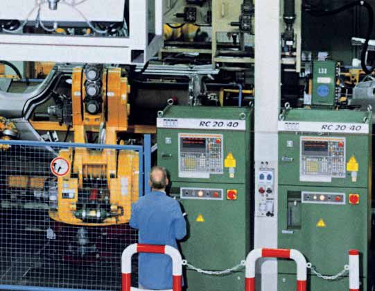
Room design
                                                         Air outlet    GEAFOL                                                                    MV equipment
    GEAFOL cast-resin transformers can be                                                                                 LV equipment
                                                         (natural      transformer
    installed in a room together with medium-            cooling)
                                                                                                            Alternative
                                                                                 Solid wall*                air outlet
    voltage and low-voltage switchgear, without

                                                                                                                                                                  3000
    the need for any special precautions. This
    produces a substantial reduction in building
                                                                                                         Guard rail
    costs for the transformer cells. The room can
                                                                         1U         1V              1W
    be up to 4 m below ground level or on the
    upper floors of buildings; which would be
    impossible if oil-immersed transformers

                                                                                                                                                                  800
                                                         Air inlet                                        Cable duct
    were to be used.
    In the case of installations which fall within
                                                                        *Refer also to Section „Protection against accidental contact“, p. 9
    the scope of the regulations Elt Bau VO, the
    doors must be of fire-resistant class F30A
    and the walls of fire-resistance class F90A
    in order to provide fire-resistant isolation of
    the electrical operating area. However, fire                                                                            Tr. 3
    walls (24 cm), such as those required with                                                                                                         Cable 1
                                                                              Transformer 3
                                                                                              630 kVA
    oil-immersed transformers, are not required
    in the case of GEAFOL transformers.                                                                                                                Cable 2

                                                                                                                                                      Power in-
                                                                                                                           Tr. 2                      strumen-
                                                                                                                                                                  6000

                                                                              Transformer 2
                                                                                              630 kVA
                                                                                                                                                      tation

                                                                                                                                                      Trans-
                                                                                                                                                      former 3

                                                                                                                                                      Trans-
                                               Fig. 2:                                                                     Tr. 1                      former 2
                          Example of arrangement to                           Transformer 1
                                                                                              630 kVA
                                       DIN VDE 0108                                                                                                   Trans-
                           with GEAFOL transformers                                                                                                   former 1
                       and switchgear in an electrical
                         operating area for supply of
                                   an office building
                                                                                                                      7500
                                                                      Self-closing doors, outward-                                 Fire resistance class
                                                                      opening, fire resistance class                                F90A to DIN 4102
                                                                      F30A to DIN 4102

8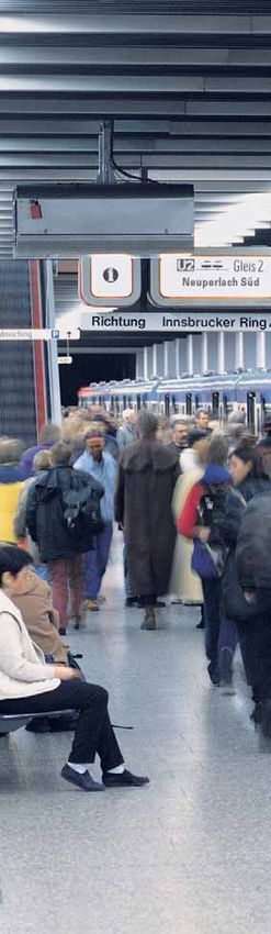
Installation requirements

                                                                                                                       Solid wall

                                                                                                                                    1800
                                                                                                  1300
                                                                                                  C
                                                                                                              A

                                                                                                  B
                                                                                                  D
Protection against accidental contact         The safe clearance D (Fig. 3) is specified        Fig. 3:
The cast-resin of the transformer winding     for use of guard rails, chains and ropes         Guard-rail protection
is not safe to touch when the transformer     installed at a height of 1100 –1300 mm.
is energized. For this reason protection
against accidental contact must be pro-       The following values apply at Um:
vided. There are a number of measures         12 kV = 500 mm
which may be taken to provide protection      24 kV = 500 mm
against accidental contact on installation    36 kV = 525 mm
of a transformer in an electrical operating
area, e.g. installation of guard rails        The safe clearance E (Fig. 4) is specified                                Solid wall

(Fig. 3) or wire mesh (Fig. 4).               for a mesh height of 1800 mm.

Examples for installation                     The following values apply at Um:

                                                                                                                                    1800
Figs. 3 and 4 depict examples of protection   12 kV = 215 mm
against accidental contact.                   24 kV = 315 mm
                                              36 kV = 425 mm
The following rule applies for the
clearances A, B and C:                        And: max. mesh size = 40 mm for wire-
   Minimum clearance (Table 2)                mesh doors and fencing.
                                                                                                  C

plus                                          The safe clearances D and E should
   30 mm safety allowance                     conform to DIN VDE 0101.
   (empirical value)
plus                                          Room division between transformers                              A
                                                                                                  B

   Installation clearance (depending on       On installation of a number of GEAFOL
   space requirements).                       transformers in a room (Figs. 2, 3 + 4)
                                                                                                  E

                                              provision of room divisions is not manda-
                                              tory; however, as a general rule, these
                                              are provided in the form of simple, non-
                                              inflammable partition walls.
                                              There are clear advantages to be gained
                                              from provision of partitions between             Fig. 4:
                                              transformers which supply different              Wire-mesh door protection
                                              networks: If it becomes necessary to
                                              de-energize one transformer, the other
                                              can remain in operation.

                                                                                                                                           9
Connection System
     Practice-oriented options for connection of the
     high-voltage and the low-voltage side are a
     distinguishing feature of the flexible connection
     philosophy of GEAFOL transformers.

     Connection of the high-voltage side
     In the standard design the HV connection of the transformer is
     at the top coil connection, connection at the bottom is available
     as an option (Fig. 5). Screwed circuit connections are used for
     the delta connection. The transformer connection is made at
     the end of the connection rods, alternatively at a straight or
     angled terminal face.

     Connection of the HV side using plug-type connectors
     Connection of the HV side using external conical plug-type
     penetrations is possible (see Fig. 6).

     High-voltage tappings
     The HV tappings allow matching to local network conditions.
     The desired tapping can be selected by means of connection
     straps and screwed connections.

     Connection of the low-voltage side
     In the standard design the LV connection of the transformer
     is also at the top coil connection, connection at the bottom is
     available as an option (Fig. 7). If intermediate expansion links
     are employed, the LV side connection is protected against
     mechanical stress and transmission of structure-borne noise.

     Connection of earthing and short-circuiting devices
     Either straight or angled conical fixed points, of diameter 20 mm
     or 25 mm, can be mounted at the conductor connections, at the
     HV side at the connection rod and at the LV side at the conductor
     terminal face.

10
1U 1V 1W
Fig. 5: Variable termination facility,
e.g. at the delta-connected HV side
Fig. 6: Plug-type HV connections
Fig. 7: LV connection systems on GEAFOL transformers
2W 2V 2U
2N
2N
2W 2V 2U
Fig. 7a: Conductor and neutral Fig. 7b: Conductor and neutral
terminal, top terminal, bottom
11Temperature Supervision
Either PTC thermistor temperature sensors, PT 100 resistance tempera-
ture detectors (RTD) or a capillary tube thermometer can be employed
for temperature supervision of GEAFOL transformers. The temperature
of the LV windings are monitored and in addition the core temperature
in the case of converter transfomers. The most economical solution is
monitoring by means of PTC thermistor sensors without indication of
the temperature. All GEAFOL transformers are provided with at least
one PTC thermistor sensor circuit for tripping purposes.
Function
Temperature monitoring by means of PTC thermistor sensors
In the case of three-phase transformers a monitoring system consists of 3 PTC
thermistor sensors connected in series – one sensor per phase – and a tripping
device.
The PTC thermistor sensors function as resistances. When the response tempera-
ture is reached, a step-change in resistance occurs and the changeover contact
in the tripping device is operated. As soon as the temperature falls below the
response temperature by approx. 3 K, the relay coil in the tripping device is once
more fully energized and the changeover contact returns to its original position.
The supervision system is fail-safe and uses a normally closed circuit. It also
provides protection against a wire-break in the sensor circuit.
When two systems are employed for temperature supervision, one is connected
to provide alarm signalling and the other tripping. The rated response tempera-
tures of both systems differ by 20 K. A third system can, for example, be used for
fan control. If the control supply is taken directly from the secondary side of the
transformer to be protected, a time relay must be used. This time relay is used to
bridge the time interval between energizing the transformer and pick-up of the
relay in the tripping device. The ambient temperature for the tripping device is
limited to 55 °C. For this reason installation of the tripping device in the medium-
Typical circuit diagram for temperature supervision
2
1 PTC thermistor sensor
1W 1V 1U 2 Tripping device
3 Alarm or trip
4 Time relay, pick-up delay
5
5 Terminal strip at the transformer
4
1
2W 2V 2U 2N 3 Alarm / trip
230 V~
Si
Fig. 8: Power supply for the tripping unit from a system fed
from the protected transformer
12Additional Forced-Air Cooling
to Increase the Transformer
Power Rating
The output rating of GEAFOL transformers up to 2500 kVA with degree of protection
IP 00 can be increased up to 50 % as a result of mounting centrifugal-flow fans.
For example, the continuous power rating of a 1000 kVA transformer can be increased
to 1500 kVA using this efficient method of forced cooling without exceeding the
permissible winding temperatures.
The rating is then given on the rating plate as rated output
1000 kVA with type of cooling AN and rated output 1500 kVA
with type of cooling AF.
Capacity can thus be held in reserve and load peaks of longer
duration can be covered.
For forced-air cooling 2 or 3 fans are mounted on each of the
two longitudinal sides.
Fan characteristics
Single-phase AC induction motor (external rotor IP 00)
Protection against accidental contact for the motor
Sound pressure level as a rule 71– 74 dB(A), and therefore
the main factor governing the noise level.
A control device is needed for starting the fans as a function
of the temperature. The fans are switched off by means of an
adjustable time relay incorporated in the control device.
On operation with fans, i.e. cooling type AF with forced-air
circulation, the following points must be taken into account:
Extra space requirement for the fans, e.g. for a
1000 kVA transformer
Length + approx. 200 mm, width + approx. 250 mm
The LV connections must be designed so that the air flow
at the coils is not interfered with
The higher power losses of the transformer: The load
losses increase as a function of the square of the load.
This is of relevance for design of the room ventilation
(refer to page 16) and for the operating costs.
Economic efficiency of additional forced-air cooling
The cost of the fans and of fan controls remain practically
constant within the output range up to 2500 kVA. In the case of
power ratings up to 400 kVA, it is generally more economical to
select a transformer with a higher output rating than to install
forced-air cooling. Continuous operation at 150 % rated power Fig. 9: Attachment of centrifugal-
output is permissible with type of cooling AF; however, in this flow fans to GEAFOL transformers
case the load losses are 2.25 times those at 100 % rated output,
for example, in the case of a 1000 kVA transformer 22.5 kW
instead of 10 kW. If a transformer of higher rated power output
is used, the load-dependent losses would be lower; however,
the no-load losses be higher. It can thus be seen that forced-air
cooling is not an economical solution for continuous operation
but is on the other hand a favorable alternative for making
available reserve capacity and for coping with load peaks.
The maintenance costs may also be increased by the use of
ventilator fans.
13Ventilation of the
Transformer Room
Heat losses inevitably occur during operation of transformers.
These losses must be dissipated from the transformer room.
The first priority is thus investigation of whether natural
ventilation is feasible. In cases where this is insufficient,
installation of mechanical ventilation (forced-air ventilation)
must be considered.
Hints for the following are given below:
Calculations for simple systems fo natural and forced ventilation
Diagrams and worked examples for dimensioning of ventilation systems
Efficient specimen ventilation systems
Assumptions
The ambient temperature of the transformers dimensioned in conformity
with VDE may not exceed +40 °C (see page 7 – average daily and annual
temperatures). The temperature sensors embedded in the low-voltage
windings are matched to this maximum value of coolant temperature plus
the winding temperature rise permitted by IEC 60076-11/VDE 0532 and
the appropriate hot-spot allowance.
It is immaterial whether the transformers are naturally cooled (type of
cooling AN) or equipped with fans for raising the output (type of cooling
AF). Whatever the circumstances, the ventilation system must always be
designed to deal with the maximum heat loss which can occur.
Effective cooling can be achieved by admitting cold air at the bottom of
the room and exhausting it to atmosphere from the opposite side just be-
neath the ceiling. If the air supply is heavily polluted it must be filtered.
QD
KD A D, K D
AW
ϑ2
A2 VL Qv = Σ Pv KW
H
V2
QW
A1 ϑ1
1U 1V 1W
V1
Q v: Total dissipated losses (kW) Q W, D: Losses dissipated through the walls
P v: Transformer losses (kW) and ceiling (kW)
v: Air velocity (m/s) A W, D: Surface area of the walls and ceiling
A 1, 2: Air inlet/outlet cross section (m2) K W, D: Heat transfer coefficient (mWK)
2
∆ϑ L: Air temperature rise (K), ∆ϑL = ϑ1 – ϑ2 Subscripts: W – wall, D – ceiling
H: Height for thermal purposes (m) VL: Air flow rate (m3/s)
Fig. 10: Data for calculation of ventilation
14Calculating the heat losses in the room This implies: AW, D = Surface area of the walls
The heat losses are caused by the power Approx. 200 m3/h air per kW heat losses and ceiling
losses of the transformer. are required at ∆ϑL = 15 K (approximate ∆ϑW, D = Temperature difference, indoors /
The power losses of a transformer are: value). outdoors
A second straight line should be drawn (see also Fig. 10).
SAF 2
Pv = P0 + 1.1 x PK120 x (S ) (kW)
AN
from the intersection point of the first
straight line with the borderline (to the In contrast to heat dissipation by air
where: right of the VL scale) to H = 5. This line circulation (Qv1), heat dissipation through
P0: No-load losses (kW) intersects the A1,2 scale at 0.78 m2 – the walls and ceiling (Qv2) is generally
1.1 x PK120 (kW): Load losses at 120 °C this is the sought value for the free cross low. It is dependent on the thickness and
(from the catalog or, if available, from section of the air inlet and outlet. The material of the walls and ceiling.
the test certificate) multiplied by the flow resistances for the inlet opening The heat transfer coefficient K is the
factor 1.1 to obtain the working tempera- with a wire grille of mesh size 10–20 mm decisive factor.
ture of class F/F insulation for the HV/LV and for the outlet opening with fixed lou-
windings of GEAFOL transformers. vres have been taken into account in the Table 3: Some examples
SAF: Rated power with type of nomogram. Use of a wire mesh instead
Material Thickness Heat transfer
cooling AF (kVA) of fixed louvres at the outlet opening
coefficient K*
SAN: Rated power with type of reduces the required cross section by cm W/m2 K
cooling AN (kVA). 10 %. Where applicable, all parts causing
Light 10 1.7
The total heat losses in the room (Qv) is constriction of the cross section must
concrete 20 1.0
the sum of the heat losses of all the be taken into account by corresponding 30 0.7
transformers in the room. increase of the cross section.
Burnt brick 10 3.1
Qv = ∑ Pv Qv2: Heat dissipation through the 20 2.2
walls and ceiling 30 1.7
Calculating the heat dissipation The following applies to that portion of the
Concrete 10 4.1
The following methods are available for heat losses which is dissipated by natural 20 3.4
dissipation of the total heat losses in the convection: 30 2.8
room (Qv):
Qv1: Heat dissipation by natural air Qv2 = (0.7 x Aw x Kw x ∆ϑw + AD x KD x ∆ϑD) Metal – 6.5
circulation x 10–3 (kW)
Glass – 1.4
Qv2: Heat dissipation through the walls
and ceiling where: *) The heat transfer coefficient K includes the
Qv3: Heat dissipation by forced-air KW, D = Coefficient of heat transmission conduction and transfer of heat at the surfaces
circulation
Qv = Pv = Qv1 + Qv2 + Qv3
QV1 (kW) VL (m3/s) A1, 2 (m2) H (m) ΔϑL = ϑ2 – ϑ1 (K)
5
Qv1: Heat dissipation by natural 20
air circulation 100 15
The following applies to that portion of 2
the heat losses which is dissipated by 10
natural convection: 8 3
50 6
Qv1 = 0.1 x A1,2 x H x ∆ϑL3 (kW) 10 4
40 4
5
For symbols refer to text of Fig. 10: 3 5
4 10
The nomogram in Fig. 11 can be used 30 6
3
for solving by graphical means. 2 7
2 8
20 1.5 9
Worked example for cooling by means 1
10
1
of natural convection. 15
15
0.8
Given: 0.7 0.5
Qv1 = ∑ Pv = 10 kW 0.6 0.4 15
10
0.5 0.3
H = 5 m; ∆ϑL = ϑ2 – ϑ1 = 15 K 20
0.4
(empirical value) 0.2 20
0.3
To be calculated: 0.2
0.1 30
5
Inlet and outlet air flow rate VL 25
Inlet and outlet cross section A1, 2 0.15
4
(Qv2 is neglected here) 0.1
3
Using the nomogram in Fig. 11: Fig. 11: Nomogram for
The first straight line is to be drawn from 2 natural ventilation of the room
Qv1 = 10 kW to ∆ϑL = 15 K. It intersects
the scale VL at 0.58 m3/s – the sought 1.5
value of the air flow rate.
1
15Qv3: Heat dissipation by forced-air The nomogram in Fig. 13 makes use
circulation of this equation. It is thus possible, for
That part of the heat loss Qv3, dissipated example, to determine the following
by forced-air circulation, usually proves parameters for an air velocity of 10 m/s
to be much larger than the components in the air ducting and for different
Qv1 and Qv2. In practice for calculation of temperature differences ∆ϑL:
forced-air cooling the following applies: Air flow rate of the air to be exhausted
Assume that Qv3 = ∑ Pv. Consequently all Cross section of the air ducting
ventilation is attributed to forced-air Cross section for air inlet/outlet
circulation and Qv1 and Qv2 provide a (approx. 4 x duct cross section).
safety margin. The heat dissipation by
forced-aircirculation is: The following relationship exists for the
ratio of the air flow rate VL, air velocity v
Qv3 = VL x CPL x ρL x ∆ϑL (kW) and the average cross section A:
where: VL = v x A
VL = Air flow rate in (m3/s)
CPL = Thermal capacity of air An air velocity of 0.6 to 0.7 m/s can be
= 1.015 kWs tolerated in transformer rooms. If the
kg x K
ρL = Air density at 20 °C room is not accessible, higher values of
= 1.18 kg/m3 air velocity can be selected.
∆ϑL = Air temperature rise (K)
= ϑ2 – ϑ1
Air ducting
The air ducting should be made of
Losses 40 38 36 34 32 30 26 22 19 17 15 ∆ϑL (K)
QV3 28 24 20 18 16 14 13 12 11 10 9 8
galvanized sheet steel or plastic (not PVC).
(kW) 100 It can be of either rectangular or circular
cross section. Installation of a fire damper
90 7 in the air duct is mandatory, where the
air duct penetrates a fire wall. The inlet
80 and outlet grilles should prevent the in-
6
gress of foreign objects and vermin.
70
The following points should be taken into
5
account: The calculated inlet/outlet cross
60
section of the air grilles should be multi-
50 4 plied by a factor of 1.7 because the
effective open cross section of the grilles
40 3
is only approx. 60 %. Adjustable louvres
permit more accurate setting of the inlet
30 air flow rate.
2
20 Room ventilation fans
1 Box-type, centrifugal or axial-flow fans
10
can be used for room ventilation. These
are available from various suppliers. The
0
VL 0 2.5 5 7.5 10 12.5 15 17.5 20 22.5 25 27.5 30 32.5 35 37.5 40 x 103 required total pressure difference (N/m2)
Air flow rate (m3/h) is of particular importance for selection
of the room ventilation fan. For calculation
AK 0 0.1 0.2 0.3 0.4 0.5 0.6 0.7 0.8 0.9 1.0 1.1 of this value reference should be made
Duct cross section (m2)
to the Section “Power rating of the room
A1,2 0 0.5 1 1.5 2 2.5 3 3.5 4 4.5 ventilation fan”. It may be necessary to
Inlet cross section (m2) employ sound dampening to reduce the
Outlet cross section (m2) operational noise of the room ventilation
fan. The silencers are installed in the air
ducts. The following points should be
Fig. 13: Nomogram for forced ventilation taken into account: The normal noise
of the room with Vduct = 10 m/s level can be amplified as a result of
special local conditions.
And: If a number of air ventilation fans
are in operation, the noise levels are
summated; refer to page 19 “Noise”.
16Ventilation of the transformer room
r=2D
2000
r=2D
r=2D
2000
2000
AK
A2
2000
4 x 1000 kVA r=2D
QV3
Fig. 12: Diagram of the
forced ventilation system A1
for the worked example
Criteria for selection of the room Typical values for the pressure loss due to 40 °C max. cooling air temperature
ventilation fan pR are: to IEC 60076-11/VDE 0532 (special
The following criteria should be checked measures are necessary in the tropics
for selection of the room ventilation fan: Table 4 with ϑ1 > 40 °C: precooling of the air,
Air delivery rate (m3/h) as a function reduction of the transformer output
Wall mounting, approx. 40–70 N/m2
of the pressure (N/m2) including louvres rating, or installation of transformers
Speed in operation (to keep the designed for the relevant higher
noise level as low as possible: Louvres approx. 10–50 N/m2 ambient temperature)
max. 600–800 min–1) Temperature difference ∆ϑL = 16 K
Operating voltage V Grilles approx. 10–20 N/m2
Power rating kW Using the nomogram (Fig. 13) the
Silencers approx. 50–100 N/m2
Frequency Hz following are found:
Sound pressure level dB (A) Flow rate of the cooling air: 10000 m3/h
Average values should be used in Cross section of the air duct: 0.28 m2
Power rating of the room the case of “free extraction” and “free Air inlet cross section 1.12 m2
ventilation fan delivery”. Fig. 12 depicts a ventilation system with
The drive rating P of the room ventilation the following components:
fans is given by the following equation: pB: Pressure difference due to acceleration 1 extraction ventilator
The following equation is valid for the (room ventilation fan)
pxV
P = 3.6 x 10L6 x η (kW) pressure difference pB (N/m2) due to 1 louvre damper
acceleration: 4 90° bends, r = 2D
where: 8 m galvanized sheet-steel, straight
p = Total pressure difference due to pB = 0.61 x vK2 (N/m2) cross section 0.7 x 0.4 m
air flow (N/m2): 1 outlet grille, free area: approx. 1.12 m2
p = pR + pB where: 1 inlet grille, free area: approx. 1.12 m2
VL = Air flow rate (m3/h) vK = Air velocity (m/s) in the duct
η = Efficiency of the fan VL = Air flow rate (m3/h) The total pressure difference of the fan
(0.7…0.9) AK = Duct cross section (m2) is obtained as follows:
Pressure loss due to flow
VL
pR: Pressure difference due to flow where: vK = 3600 x AK
plus
The pressure difference occurs as a result of: Pressure loss due to acceleration:
The frictional resistance pR in the Worked example for forced-air circulation – p = pR + pB
straight duct = duct length L x specific refer to Figs. 12 and 13.
duct frictional resistance pRO Given: Determining of the components:
Individual resistances due to bends, 4 GEAFOL transformers, each rated pR: Pressure difference due to flow
branches, grilles and changes in at 1000 kVA The pressure loss due to flow is the sum
cross section. Total heat losses of the following losses:
Qv3 = ∑ Pv = 4 x 12.9 kW = 51.6 kW 1. Frictional resistance in the duct
(Qv1 und Qv2 are neglected and 2. The resistances of individual components
represent a safety margin)
17Ventilation of the transformer room
VL
(m3/h) (m3/s)
54000 15
AK 80 D
(m2) (mm)
90
36000 10
0.008 100
28800 8
0.01
21600 6 120
VDuct PRO
1800 5 (m3/s) (Pa•m) 0.015
14400 4 150
0.02
10800 3 1000
100 500 0.03 200
7200 2 200
50 0.04
100
50 240
5400 1.5 0.05
20 20
10 300
3600 1
5 0.08
2880 0.8 10
2 0.1
1
2160 0.6 5 400
0.5
1800 0.5 0.15
0.2
1440 0.4 2 0.1 0.2 500
1080 0.3
1 600
0.3
Fig. 14: Nomogram for 720 0.2 0.5 0.4 700
determining of the
540 0.15 0.5 800
pressure difference of
air ducting – here for 0.2
air density 1.18 kg/m3
and 20 °C. r=2D 0.1 0.2 0.5 1 2 5 10 20 50 100 200 500 Pa
For the scale PR
designations refer to 1 1.5 2 3 4 6 8 10 15 20 30 40 60 vDuct (m/s)
page 16. r=0 PR
0.5 1 2 5 10 20 50 100 200 500 1000 2000 4000 Pa
1. Pressure loss due to frictional resistance Total pressure difference due to flow
in the ducting The total pressure difference due to flow is thus
The pressure loss per metre duct can be read off the
pR0 scale in the nomogram (Fig. 14): as the intersection pR = Sum of the frictional losses
of the straight lines connecting the already determined = 12 + 138 = 150 Pa
values for VL and AK or D, as the case may be. AK applies pB: Pressure difference due to acceleration
to ducts of rectangular cross section and D to ducts of pB (Pa) is found from the equation:
circular cross section. pB = 0.61 x v2K (vK in m/s)
In our example – connecting straight line Fig. 14 – the
specific frictional resistance per metre duct is found to be In the example: vK = 10 m/s
The pressure difference due to acceleration is found to be:
pR0 = 1.5 m2Nx m
pB = 0.61 x 102 = 61 Pa
For a total duct length L of 8 m:
Result: Total pressure difference of the fan
pR = pR0 x L = 1.5 x 8 = 12 Pa The total pressure difference of the ventilation fan
is thus for the example given
2. Pressure loss due to individual components
The values for the pressure loss due to individual p = pR + pB = 150 + 61 = 211 Pa
components are found from Fig. 14 and Table 4.
In the example: It is therefore necessary to use a ventilation fan
4 90° bends, r = 2D, vK = 10 m/s with an air delivery rate of 10000 m3/h and a total
each 12,0 Pa 48 Pa pressure difference of 211 Pa.
1 inlet grille 20 Pa It is usually not necessary to calculate the drive
1 outlet grille 20 Pa power, if the manufacturer is given the delivery rate
1 louvre (exhaust) 50 Pa and the total pressure difference of the fan.
∑ pR = 138 Pa
18Noise
Special design measures have reduced the noise level of GEAFOL cast-resin
dry-type transformers to that of oil-immersed transformers.
The noise level values are to be found in the catalog “GEAFOL cast-resin
transformers 100 kVA to 16,000 kVA”, Order-no. E50001-K7101-A101-A5-7600.
These values meet the requirements of the Standard. Noise is caused as a
result of magnetostriction of the core laminations. In the case of distribution
transformers noise is dependent on the induction and not on the load. The
noise level can be increased by voltage harmonics, e.g. caused by converter
operation.
The sound sensitivity of the ear This extensive pressure range is subdivided In the sound sensitive range of the ear
Sound in the present context is defined on a logarithmic basis. Ten-fold increase defined by frequency and sound pressure,
as compressive oscillations of the elastic of the sound pressure P with respect to viz. the auditory sensation area (see Fig. 15),
medium air within the audible frequency the reference value is defined as 1 Bel = sound sensations with identical sound
range. The ear interprets the frequency 10 Dezibel (dB). (The sound power level pressure p but of different frequency are
of such compressive oscillations as pitch is proportional to the square of the sound not experienced as being identically loud.
and the pressure amplitude as loudness. pressure P.) The following relationships For this reason the auditory sensation
While the amplitude of the alternating are thus obtained for the “sound level” L: area is divided into curves of identical
sound pressure p and the frequency “loudness”.
p2
can be measured precisely as physical L = 10 lg PP = 10 lg p 02
(dB)
0
parameters, the subjective sensitivity of the Approximation of the ear characteristics
ear to noise cannot be measured directly. Since sound measurements are based on using instrumentation
Oscillations with frequencies below 16 Hz measurement of the sound pressure, Evaluation of noise by measurement of
and above 16 kHz are not interpreted as equation (1) is the most frequently used the sound level must take frequency-
sound by the ear. The receptivity of the relationship. The sound pressure of dependent ear sensitivity into account.
ear for sound pressure extends from approx. 2 x 10⁻⁴ bar at the threshold of Low and high frequencies measured within
2 x 10⁻⁴ µbar at the hearing threshold to hearing is the reference value p0. the noise spectrum must be evaluated to
2 x 10³ µbar at the pain threshold. a greater extent than medium frequencies
P
(1) L = 20 lg P (dB) (filter) in a manner corresponding to the
0
curves of equal loudness.
The evaluation curve A (see Fig. 15)
represents an approximation of the curve
of equal loudness within the frequency
Sound pressure level referred to 20 µN/m2 (= 2 x 10⁻⁴ µbar)
range up to 500 Hz.
dB 140 µbar
140 2 x 10 3
110
100
120
120 90 2 x 10 2
80
70
100
100 60 2 x 10 1
Sound pressure
50
40
30 80
80 20 2
10
60
60 A-weighted sound-pressure level 2 x 10⁻¹
40
40 2 x 10⁻²
20
20 2 x 10⁻³
Threshold of 10 Fig. 15: Threshold of hearing
hearing -4 and curves of equal loudness
0 phon 2 x 10
for sinewaves for binaural
20 31.5 63 125 250 500 Hz1 2 4 8 16 kHz listeners in an open sound field
Frequency
19dB
Propagation of noise Measures for noise reduction 15
Operational noise of transformers is Air-borne noise
Increase in noise level
propagated locally in the form of air- Air-borne noise is amplified by reflections
borne noise and structure-borne noise. at the walls and ceiling of the transformer 10
Different noise reduction measures must room. The following parameters are of 8
be used for each type of noise. Main relevance for sound reflection:
objective of noise reduction: Compliance AR = total surface area of the room 5
with the specified values at the site AT = transformer surface area 3
boundaries or at the boundary of an α = acoustical absorption coefficient
adjacent site. of the walls and ceiling 0
Fig. 18 shows how these factors determine 1 2 4 5 10 15 20 25
Number of sources having
Sound power level noise generation.
the same noise level
The sound power level provides a measure
Fig. 16: Increase in noise level for
of the noise produced by a sound source. Some examples of the acoustical absorp-
a number of sound sources having
It characterizes the noise of the source and, tion coefficient a for different building identical sound level
in contrast to the sound pressure level, is materials are given below, here for 125 Hz.
independent of the point of measurment
and of the acoustical properties of the Table 5: Transformer surface area AT (approx.
dB
environment. figure) with the corresponding value for the 65
The method for determining of the enveloping surface L S
L SR value
sound power level LWA is given in 60
Sr (kVA) AT (m2) L S 0.3 m (dB)
IEC/EN 60076-10 (VDE 0532 T76-10). 55
Noise power levels are maximum values 100 3.8 6
without tolerance. 160 4.4 6.5
50
The noise power level is to be determined
250 4.7 7 45
as follows:
Determining of the sound pressure level 400 5.5 7.5 40
LpA on a defined enveloping surface 630 6.4 8
35
around the transformer plus 1000 8.4 9 30 40 60 100 150 300 500 m
Logarithm of the enveloping surface S. Distance R
1600 10 10
Fig. 17: L SR value as a
As an equation: 2500 14 11.5
function of distance R
LWA = LpA + L S
Table 6
where: Acoustical
Building materials for
the value for the absorption dB
S transformer room coefficient α 30
enveloping surface L S = 10 x lg S =0
2
0 .01
(refer to Table 5) S0 = 1 m Brick wall, unplastered 0.024 ∆L 25
0.0
2
20 0.0
Dependency of the sound pressure on the Brick wall, plastered 0.024 5
distance 0.1
15
LpA = audible and measurable sound pres- Concrete 0.01 0.2
sure level at a distance R ≥ 30 m using the 10 0.4
3 cm glass-fibre panel on 0.22
equation given above it follows that: hard backing 5
LpA = LWA – L SR 0.8
4 cm mineral wool with 0.74
2
0
where L SR = 10 lg 2πR smooth board covering 1 2 3 4 6 8 10 20 30
S0
AR/AT
The diagram in Fig. 17 depicts the value LSR It is thus possible to reduce the operational Fig. 18: Increase in operational noise in
as a function of the distance R. It is thus noise due to reflections by lining the trans- the transformer room due to reflection
easily possible to determine the magnitude former room, e.g. to a very significant extent
of the sound pressure level LpA of a trans- though use of mineral wool. This effect is
former at a specific distance (refer also to evident in Fig. 18.
dB
DIN EN 60551). The sound pressure level in the room is atten- 40
uated on propagation through the walls.
Noise reduction
An example:
30
LWA = 70 dB and R = 35 m Examples for the insulating effect:
Brick wall, 12 cm thick = 35 dB (A) 24
Using these values in the diagram: insulation 20
L SR = 39 dB Brick wall, 24 cm thick = 39 dB (A)
insulation 10
Consequently the free-field sound The insulating effect of doors and air duct-
pressure level is: ing must be taken into account; as a general
0
rule they reduce the room insulating effect.
1 2 5 10 20 30 50 100 150
LpA = 70 dB – 39 dB = 31 dB The sound pressure level outside the trans- Distance m
former room is continuously reduced as
Fig. 19: Reduction of the noise pressure
function of distance (see Fig. 19). level as a function of the distance
20Noise
Fig. 20: Anti-vibration mounting for structure-borne
noise insulation of transformers
Structure-borne noise Insulation against structure-borne noise: Solution:
Transformer noise is propagated via the Dimensioning The force (F) per supporting point is:
contact surfaces between the transformer In order to achieve adequate insulation Transformer mass x g
F = Number of mounting points
and the floor to the walls and other parts of structure-borne noise, the natural
of the transformer room. frequency of the vibration system com- in this case
Structure-borne noise insulation of the prising the transformer and insulating
2630 x 10
transformer reduces or completely inter- device must be low in relation to the F= 4
= approx. 6575 N
rupts sound propagation via this path. exciting frequency.
The magnitude of the primary operation Proven in practice: Insulating devices, The required spring constant is thus:
noise cannot be reduced by this method. whose elastic compression s is at least CD = Fs
However: The room insulation is optimized 2.5 mm under the weight F of the trans-
6575
as a result of provision of structure-borne former. = 0.25
= 26300 N/cm
noise insulation. In many cases it is thus The maximum permissible load of the
possible to completely dispense with insulating devices must be taken into For ordering purposes the following is
cladding of the walls using acoustical account. The spring constant CD (N/cm). recommended: Selection of 4 mounting
absorption material, e.g. with mineral It is calculated as follows: devices with spring constant ≤ 23400 N/cm
wool. and ≥ 8500 N permissible steady-state
Resilient walls and special anti-vibration CD = Fs continuous load.
mountings (see Fig. 20) are employed
for structure-borne noise insulation of Structure-borne noise insulation Special features:
GEAFOL transformers. And: Elastic adapters Worked example Increased oscillation of the foundation
are available for busbar connection of the An example for calculation of structure- is to be expected, if the transformer is
low-voltage switchgear, thus ensuring borne noise insulation is given below: installed on an upper floor of a building.
optimum structure-borne noise insulation 1 GEAFOL cast-resin dry-type In this case an elastic compression s of
in the complete transformer room. transformer rated at 1000 kVA up to 0.5 cm is recommended.
Transformer mass: 2630 kg
4 mountings for insulation
Location: Basement – e.g. on a
solid foundation, resulting elastic
compression s = 0.25 cm
g = gravitational acceleration =
m
9.81 S2
21Noise
A
Room dimensions: 8000 x 5000 x 4000
Fig. 21: Diagram of 2 x 630 kVA
the worked example
Noise level in the room next to the The following relationship applies for
transformer room: Worked example noise amplification due to reflection:
In this example, the approximate noise
AR 184 m2
level in the room A adjacent to the AT
= 6.4 m2
= 29
transformer room is to be calculated
(see Fig. 21). For an acoustical absorption coefficient
α = 0.01 (concrete walls), from the
The following parameters are known: diagram, Fig. 18
2 GEAFOL cast-resin dry-type
transformers each rated at 630 kVA ∆L = + 12 dB (A)
Structure-borne noise insulation has
been provided plus
Air-borne noise propagation to room A as per diagramm, Fig. 16
through the floor only Increment for 2 transformers (2 sound
Transformer room inner surface sources) + 3 dB (A)
AR = 184 m2; adjacent room A has
the same dimensions This results in
Surface area of a transformer AT = 6.4 m2 57 dB (A) + 12 dB (A) + 3 dB (A) = 72 dB (A)
Floor area of the room AF = 40 m2;
Walls of concrete, 24 cm thick minus
insulation by concrete ceiling
Solution: (24 cm) = 39 dB
Sound power level of the transformer
from catalog or diagram, Fig. 15: Thus the sound pressure level propagated
to room A = 33 dB (A).
LWA = 70 dB
To this must be added: Amplification of the
The following equation gives the sound sound pressure level in the adjacent room
pressure near the transformer (≈ 1 m): (of identical size) due to reflection:
AR 184 m2
LpA = LWA – L S 0.3 m – 5 dB; AF
= 40 m2
= 4.6
5 dB is the attenuation of the noise level For an acoustical absorption coefficient
on increase of the distance α = 0.6 in the adjacent room (estimated
LS = 0.3 m to 1 m; with carpets, curtains, etc.) we find from
the diagram, Fig. 18, that:
where:
AT
L S 0.3 m ≈ 10 lg 1 m2
= 10 lg 6.4 = 8 dB ∆L = + 3 dB (A)
Thus the sound pressure is: Result:
LpA = 70 – 8 – 5 = 57 dB (A) The total sound pressure level in room A is:
33 + 3 = 36 dB (A).
22EMC of
Distribution Transformers
Electrical and magnetic fields occur on operation of transformers.
The electric field of oil-immersed and GEAFOL transformers and of
their connections has practically no effect outside the transformer
cell or the enclosure of the transformer. The tank and the covers of
oil-immersed transformers and the protective housing of GEAFOL
transformers act as Faraday cages. This also applies to a considerable
extent to the ceiling and walls of the transformer cells, provided
these are not constructed of insulating material.
Interference can be caused by the magnetic fields. The stray
field of a GEAFOL transformer of rated output 630 kVA and
a short-circuit voltage of 6 % is approx. 5 µT at rated load at a
distance of 3 m from the transformer; the equivalent value for
an oil-immersed transformer with identical data is approx. 3 µT.
The approximate value for the magnetic field in the range from
a = 1 to 10 m for GEAFOL transformers of varying ratings and
short-circuit voltages can be found using the following equation:
u Sn
B = 5 µT 6 %z (3m)2.8
630 kVA a
In the case of oil-immersed transformers the initial value
is approx. 3 µT.
The 26th implementation order for the Federal Environmental
Protection Law (Regulations for electromagnetic fields –
26. BimSchV) dated December 16, 1996, allows a maximum
electric field strength of 5 kV/m and a maximum magnetic flux
density of 100 µT at the exposure point for 50 Hz fields. The
point of exposure is the point with the most marked effect, to
which persons can have access over appreciable periods of time.
The electric field outside the transformer cell or the enclosure
and the magnetic field at distances in excess of 3 m do not
come anywhere near the permitted limit values in the case
of distribution transformers. Interference can be caused to
computer monitors from approx. 1 µT. Detailed information is
to be found in the leaflet „Distribution transformers and EMC“
(Order No. E50001-U410-A14-X-7600).
CE marking
Transformers are to be considered as passive elements in ac-
cordance with IEC 60076-11. CE marking is not permissible in
accordance with the COTREL statement.
23Siemens AG
Power Transmission and Distribution
Transformers Division
Transformatorenwerk Kirchheim
Hegelstraße 20
73230 Kirchheim/Teck
Germany
Tel.: +49 (0) 7021 508-0
Fax: +49 (0) 7021 508-495
Siemens Transzformátor Kft.
1214 Budapest
II. Rákóczi Ferenc u.189.
Hungary
Tel. +36 (1) 278 5300
Fax +36 (1) 278 5335
www.siemens.com/energy
For more information, contact our Order No. E50001-U413-A47-V2-7600
Customer Support Center. Printed in Germany
Dispo 19201
Phone: +49 180/524 70 00
TH 101-060451 101928 WS 09062.5
Fax: +49 180/524 24 71
(Subject to charges: e. g. 0,12 €/min)
E-mail: support.energy@siemens.com
www.siemens.com/energy-support
The information in this document contains general descriptions of the technical options available, which do not always have to be present in individual cases.
The required features should therefore be specified in each individual case at the time of closing the contract.You can also read