Pressure sensor module up to 1,000 bar, model MTF-1 Drucksensormodul bis 1.000 bar, Typ MTF-1 - Drucksensormodul, Typ MTF-1 - WIKA
←
→
Page content transcription
If your browser does not render page correctly, please read the page content below
Installation instructions
                             Einbauanleitung

Pressure sensor module up to 1,000 bar, model MTF-1 EN

Drucksensormodul bis 1.000 bar, Typ MTF-1                DE

             Drucksensormodul, Typ MTF-1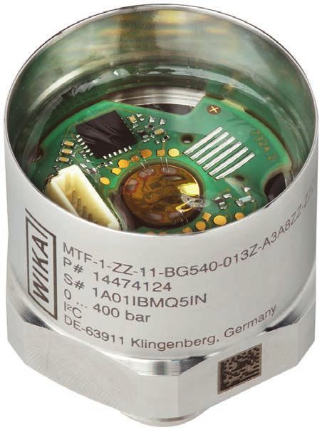
EN Installation instructions model MTF-1                                        Page              3 - 20

DE Einbauanleitung Typ MTF-1                                                    Seite           21 - 37

   © 06/2021 WIKA Alexander Wiegand SE & Co. KG
   All rights reserved. / Alle Rechte vorbehalten.
                                                                                                              14401881.01 06/2021 EN/DE

   WIKA® is a registered trademark in various countries.
   WIKA® ist eine geschützte Marke in verschiedenen Ländern.

   Prior to starting any work, read the installation instructions!
   Keep for later use!

   Vor Beginn aller Arbeiten Einbauanleitung lesen!
   Zum späteren Gebrauch aufbewahren!

    2                                                           WIKA installation instructions, model MTF-1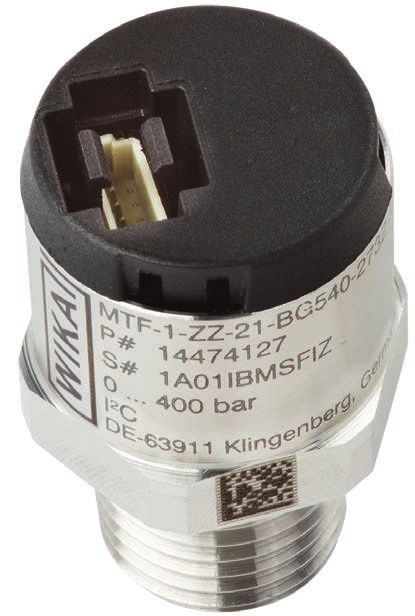
Contents

                            Contents
                            1. General information                                                                                         4
                                                                                                                                               EN
                            2. Design and function                                                                                         5
                                2.1 Overview  .   .   .   .   .   .   .   .   .   .   .   .   .   .   .   .   .   .   .   .   .   .   . 5
                                2.2 Scope of delivery  .  .  .  .  .  .  .  .  .  .  .  .  .  .  .  .  .  .  .  . 5
                            3. Safety                                                                                                      5
                                3.1 Explanation of symbols  .  .  .  .  .  .  .  .  .  .  .  .  .  .  .  .  .  . 5
                                3.2 Intended use  .  .  .  .  .  .  .  .  .  .  .  .  .  .  .  .  .  .  .  .  .  . 6
                                3.3 Improper use  .   .   .   .   .   .   .   .   .   .   .   .   .   .   .   .   .   .   .   .   .   . 7
                                3.4 Responsibility of the operator   .   .   .   .   .   .   .   .   .   .   .   .   .   .   .   . 7
                                3.5 Personnel qualification  .   .   .   .   .   .   .   .   .   .   .   .   .   .   .   .   .   .   . 8
                                3.6 Personal protective equipment  .   .   .   .   .   .   .   .   .   .   .   .   .   .   .   . 8
                                3.7 Labelling, safety marks  .  .  .  .  .  .  .  .  .  .  .  .  .  .  .  .  .  . 9
                            4. Transport, packaging and storage                                                                            9
                                4.1 Transport  .   .   .   .   .   .   .   .   .   .   .   .   .   .   .   .   .   .   .   .   .   .   . 9
                                4.2 Packaging and storage  .  .  .  .  .  .  .  .  .  .  .  .  .  .  .  .  .  . 9
                            5. Commissioning, operation                                                                                   10
                            6. Faults                                                                                                     11
                            7. Maintenance and cleaning                                                                                   12
                            8. Dismounting, return and disposal                                                                           12
                                8.1 Dismounting  .  .  .  .  .  .  .  .  .  .  .  .  .  .  .  .  .  .  .  .  .  . 12
                                8.2 Return  .   .   .   .   .   .   .   .   .   .   .   .   .   .   .   .   .   .   .   .   .   .   .   . 13
                                8.3 Disposal  .  .  .  .  .  .  .  .  .  .  .  .  .  .  .  .  .  .  .  .  .  .  . 13
                            9. Specifications                                                                                             14
                            10. Accessories                                                                                               19
14401881.01 06/2021 EN/DE

                             WIKA installation instructions, model MTF-1                                                                  3
1. General information
1. General information
■ The pressure sensor module described in the installation instructions has been
designed and manufactured using state-of-the-art technology. All components
EN are subject to stringent quality and environmental criteria during production. Our
management systems are certified to ISO 9001 and ISO 14001.
■ These installation instructions contain important information on handling the pressure
sensor module.
■ Observe the relevant local accident prevention regulations and general safety
regulations for the pressure sensor module's range of use.
■ The general terms and conditions contained in the sales documentation shall apply.
■ Subject to technical modifications.
■ Further information:
- Internet address: www.wika.de / www.wika.com
- Relevant data sheet: PE 83.01
- Application consultant: Tel.: +49 9372 132-0
Fax: +49 9372 132-406
info@wika.de
14401881.01 06/2021 EN/DE
4 WIKA installation instructions, model MTF-12. Design and function / 3. Safety
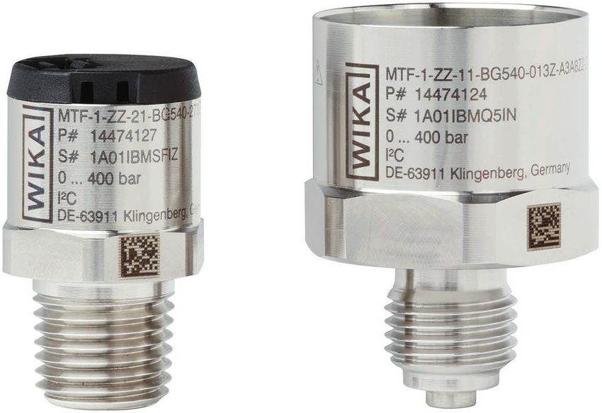
2. Design and function
2.1 Overview
EN
Cover (only with 19-mm version)
JST female connector
Housing with nameplate
Spanner flats
WIKA internal manufacturing code
Process connection
Potting
2.2 Scope of delivery
Cross-check scope of delivery with delivery note.
3. Safety
3.1 Explanation of symbols
WARNING!
... indicates a potentially dangerous situation that can result in serious
injury or death, if not avoided.
14401881.01 06/2021 EN/DE
CAUTION!
... indicates a potentially dangerous situation that can result in light injuries
or damage to property or the environment, if not avoided.
WIKA installation instructions, model MTF-1 53. Safety
Information
... points out useful tips, recommendations and information for efficient
and trouble-free operation.
EN
3.2 Intended use
This pressure sensor module is used for the conversion of pressure into an electrical
signal. In addition, a temperature value is output via the digital I²C signal. This
temperature value does not correspond directly to the medium temperature, since it is
measured on the electronics of the module. The module is used as a component for
products with integrated pressure measurement. For applications with direct contact
with foodstuffs this pressure sensor module is not suitable.
The model MTF-1 was developed for pressure measurement in non-hazardous process
media, i.e. for media of fluid group 2 in accordance with directive 2014/68/EU article 13,
such as industrial working fluids (liquids and gases) like hydraulic oils, breathing air,
nitrogen, etc.
The use with hazardous media, i.e. media of the fluid group 1 in accordance with
2014/68/EU article 13, is excluded.
The only exception to this restriction is the model MTF-1, marked “O2” for use with
oxygen, e.g. in oxygen supply and distribution stations. This variant may be used with
oxygen, a fluid group 1 medium in accordance with 2014/68/EU article 13.
The pressure sensor module must not be used in applications with unstable fluids,
especially hydrogen.
This pressure sensor module is not permitted to be used in hazardous areas!
The pressure sensor module has been designed and built solely for the intended use
described here, and may only be used accordingly.
The technical specifications contained in these installation instructions must be
observed. Improper handling or operation of the pressure sensor module outside of its
technical specifications requires the instrument to be taken out of service immediately
and inspected by an authorised WIKA service engineer.
The manufacturer of the pressure measuring instrument, i.e. the person who installs the
model MTF-1 pressure sensor module in a pressure measuring instrument, machine
or other, must inform the user about the specification, the use as well as the limits (e.g.
14401881.01 06/2021 EN/DE
limit values of the load) of the pressure measuring instrument. The manufacturer of the
pressure measuring instrument must, when manufacturing the pressure measuring
instrument, observe the installation instructions in order not to change the pressure-
bearing properties.
6 WIKA installation instructions, model MTF-13. Safety
The manufacturer of the pressure measuring instrument is responsible for compliance
with the CE requirements in respect of EMC immunity and emitted interference in the
overall system.
The model MTF-1 must be operated within the specifications and load limits which EN
are defined in the installation instructions. If the model MTF-1 is operated outside of
the specified measuring range, operating up to the overpressure limit, this is not a
permanently permissible operating state.
Handle electronic precision measuring instruments with the required care (protect from
humidity, impacts, strong magnetic fields, static electricity and extreme temperatures,
do not insert any objects into the instrument or its openings). Plugs and sockets must be
protected from contamination.
The manufacturer shall not be liable for claims of any type based on operation contrary
to the intended use.
3.3 Improper use
WARNING!
Injuries through improper use
Improper use of the pressure sensor module can lead to hazardous
situations and injuries.
▶ Refrain from unauthorised modifications to the pressure sensor module.
▶ Do not use the pressure sensor module within hazardous areas.
▶ The pressure sensor module should not be used with abrasive or
unstable fluids, in particular not with hydrogen.
Do not use the pressure sensor module for applications with direct contact with
foodstuffs.
Any use beyond or different to the intended use is considered as improper use.
3.4 Responsibility of the operator
The module is used in the industrial sector. The operator is therefore responsible for
legal obligations regarding safety at work.
The safety instructions within these installation instructions, as well as the safety, accident
14401881.01 06/2021 EN/DE
prevention and environmental protection regulations for the application area of the module
must be maintained.
The operator must ensure the compatibility of the medium with the material used.
WIKA installation instructions, model MTF-1 73. Safety
Avoid plant conditions which can lead to the formation of atomic hydrogen in the
connection channel of the sensor.
The shock and vibration test must be carried out on the end device and ensured by the
EN manufacturer of the pressure measuring instrument.
3.5 Personnel qualification
WARNING!
Risk of injury should qualification be insufficient
Improper handling can result in considerable injury and damage to property.
▶ The activities described in these installation instructions may only be
carried out by skilled personnel who have the qualifications described
below.
Skilled personnel
Skilled personnel, authorised by the operator, are understood to be personnel who, based
on their technical training, knowledge of measurement and control technology and on their
experience and knowledge of country-specific regulations, current standards and directives,
are capable of carrying out the work described and independently recognising potential
hazards.
Special operating conditions require further appropriate knowledge, e.g. of aggressive
media.
3.6 Personal protective equipment
The personal protective equipment is designed to protect the skilled personnel from
hazards that could impair their safety or health during work.
The design of the personal protective equipment must take into account all operating
parameters of the place of use.
The requisite personal protective equipment must be provided by the operating company.
14401881.01 06/2021 EN/DE
8 WIKA installation instructions, model MTF-13. Safety / 4. Transport, packaging and storage
3.7 Labelling, safety marks
Product label (example)
EN
DE-63911 Klingenberg Made in Germany
Model incl. model code
P# article number
S# serial number
Measuring range
Additional text (optional), e.g. oxygen version marked with “O2”
Coded date of manufacture
Output signal
4. Transport, packaging and storage
4.1 Transport
Check the pressure sensor module for any damage that may have been caused by
transport.
Obvious damage must be reported immediately.
CAUTION!
Damage through improper transport
With improper transport, a high level of damage to property can occur.
▶ When unloading packed goods upon delivery as well as during internal
transport, proceed carefully and observe the symbols on the packaging.
▶ With internal transport, observe the instructions in chapter 4.2
“Packaging and storage”.
4.2 Packaging and storage
Do not remove packaging until just before mounting.
14401881.01 06/2021 EN/DE
Keep the packaging as it will provide optimum protection during transport (e.g. change
in installation site, sending for repair).
Permissible conditions at the place of storage:
■ Storage temperature: -40 ... +70 °C [-40 ... +158 °F]
■ Air humidity: 45 ... 75 % relative humidity (non-condensing)
WIKA installation instructions, model MTF-1 94. Transport, packaging ... / 5. Commissioning, operation
Store the pressure sensor module in its original packaging in a location that fulfils the
conditions listed above. If the original packaging is not available, pack and store the
pressure sensor module as described below:
1. Wrap the pressure sensor module in an antistatic plastic film.
EN 2. Place the pressure sensor module, along with the shock-absorbent material, in the
packaging.
3. If stored for a prolonged period of time (more than 30 days), place a bag containing
a desiccant inside the packaging.
5. Commissioning, operation
Mounting the pressure sensor module
■ Observe the recommended tightening torque for the thread in accordance with the
corresponding standard.
■ Before installation and removal, ensure that the instrument has been made free from
pressure.
■ Comply with the max. permissible pressures (→ see chapter 9 “Specifications”).
■ Information on tapped holes can be found in Technical information IN 00.14 at www.
wika.com, in the relevant standard or by contacting WIKA.
Any technical change to the pressure sensor module is generally not permitted.
This restriction does not apply to the model MTF-1 with a spanner width of 27 mm, for which
the welding of further components to the case is possible, in principle. Laser welding is
recommended for this purpose. With this, the heating of the pressure sensor module must
not exceed the specified ambient temperature range.
→ For technical details, contact WIKA.
For contact details, please see chapter 1 “General information” or the back
page of the operating instructions.
For the model MTF-1 with spanner width 19 mm, the welding on of further components
is not intended.
CAUTION!
Damage to the pressure sensor module
14401881.01 06/2021 EN/DE
When working on open electric circuits (printed circuit boards) there is a
risk of damaging sensitive electronic components through electrostatic
discharge.
▶ The correct use of grounded working surfaces and personal armbands
is required.
10 WIKA installation instructions, model MTF-16. Faults
6. Faults
WARNING!
Physical injuries and damage to property and the environment
caused by hazardous media EN
Upon contact with hazardous media (e.g. oxygen, acetylene, flammable
or toxic substances), harmful media (e.g. corrosive, toxic, carcinogenic,
radioactive), and also with refrigeration plants and compressors, there is a
danger of physical injuries and damage to property and the environment.
Should a failure occur, aggressive media with extremely high temperature
and under high pressure or vacuum may be present at the pressure
sensor module.
▶ For these media, in addition to all standard regulations, the appropriate
existing codes or regulations must also be followed.
▶ Wear the requisite protective equipment.
For contact details, please see chapter 1 “General information” or the back
page of the operating instructions.
Faults Causes Measures
No output signal Cable break Check the continuity
Deviating zero point Overpressure limit exceeded Maintain permissible
signal overpressure limit
Too high/low working temperature Observe the permissible
temperatures
Constant output Mechanical overload caused by Replace pressure sensor
signal upon change in overpressure module; if it fails repeatedly,
pressure contact the manufacturer
Signal span varies EMC interference source in the Shield pressure sensor
environment, e.g. frequency module; cable shield; remove
converter source of interference
Signal span varies/ Too high/low working temperature Observe the permissible
inaccurate temperatures
Signal span drops/too Mechanical overload caused by Replace pressure sensor
small overpressure module; if it fails repeatedly,
14401881.01 06/2021 EN/DE
contact the manufacturer
WIKA installation instructions, model MTF-1 117. Maintenance and cleaning / 8. Dismounting, return ...
7. Maintenance and cleaning
For contact details, please see chapter 1 “General information” or the back
EN page of the operating instructions.
Maintenance
This pressure sensor module is maintenance-free.
8. Dismounting, return and disposal
WARNING!
Physical injuries and damage to property and the environment
through residual media
Residual media on the dismounted pressure sensor module can result in a
risk to persons, the environment and equipment.
▶ Wear the requisite protective equipment.
▶ Observe the information in the material safety data sheet for the
corresponding medium.
▶ Wash or clean the dismounted pressure sensor module, in order to
protect persons and the environment from exposure to residual media.
8.1 Dismounting
WARNING!
Physical injuries and damage to property and the environment
through residual media
Upon contact with hazardous media (e.g. oxygen, acetylene, flammable
or toxic substances), harmful media (e.g. corrosive, toxic, carcinogenic,
radioactive), and also with refrigeration plants and compressors, there is a
danger of physical injuries and damage to property and the environment.
▶ Before storage of the dismounted pressure sensor module (following
use) wash or clean it, in order to protect persons and the environment
from exposure to residual media.
▶ Wear the requisite protective equipment.
▶ Observe the information in the material safety data sheet for the
corresponding medium.
14401881.01 06/2021 EN/DE
12 WIKA installation instructions, model MTF-18. Dismounting, return and disposal
8.2 Return
Strictly observe the following when shipping the pressure sensor module:
All pressure sensor modules delivered to WIKA must be free from any kind of hazardous
substances (acids, bases, solutions, etc.) and must therefore be cleaned before being EN
returned.
WARNING!
Physical injuries and damage to property and the environment
through residual media
Residual media on the dismounted pressure sensor module can result in a
risk to persons, the environment and equipment.
▶ With hazardous substances, include the material safety data sheet for
the corresponding medium.
▶ Clean the pressure sensor module
When returning the pressure sensor module, use the original packaging or a suitable
transport packaging.
To avoid damage:
1. Wrap the pressure sensor module in an antistatic plastic film.
2. Place the pressure sensor module, along with the shock-absorbent material, in the
packaging.
Place shock-absorbent material evenly on all sides of the transport packaging.
3. If possible, place a bag containing a desiccant inside the packaging.
4. Label the shipment as carriage of a highly sensitive measuring instrument.
Information on returns can be found under the heading “Service” on our
local website.
8.3 Disposal
Incorrect disposal can put the environment at risk.
Dispose of instrument components and packaging materials in an environmentally
compatible way and in accordance with the country-specific waste disposal regulations.
Do not dispose of with household waste. Ensure a proper disposal in
accordance with national regulations.
14401881.01 06/2021 EN/DE
WIKA installation instructions, model MTF-1 139. Specifications
9. Specifications
Specifications
EN
Measuring range → See product label
Overpressure limit 1)
Measuring ranges 2 times
≤ 600 bar/7,500 psi
Measuring ranges 1.43 times
> 600 bar/7,500 psi
Vacuum resistance Yes
Signal noise ≤ ±0.2 % of span
Non-repeatability per IEC 62828-1 ■ ≤ 0.1 % of span for analogue signals and I²C with
oversampling ≥ 4
■ ≤ 0.15 % of span for I²C with oversampling < 4
Temperature error → See below
Temperature error
≥ 10 bar
3,0
2,0
Temperature error (%)
1,0
0,0
-40 -20 0 20 40 60 80 100 120 130
-1,0
-2,0
-3,0
Temperature range (°C)
For pressure ranges < 10 bar/150 psi, a higher temperature error at below -20 °C [-4 °F]
and above 60 °C [140 °F] must be taken into account.
14401881.01 06/2021 EN/DE
14 WIKA installation instructions, model MTF-19. Specifications
Specifications
Influence of supply voltage Max. ±0.1 %/10 V (for signal 1 ... 10 V)
Long-term drift per IEC 62828-1 ≤ ±0.1 % of span
Reference conditions Per IEC 62828-1 EN
Output signal → See product label
Load in Ω
DC 1 … 10 V ≥ 10 k
DC 0.5 … 4.5 V ratiometric ≥ 4.5 k
Measuring rate > 1 kHz
Signal clamping (optional for analogue signals)
DC 1 … 10 V Zero point DC 0.5 V
Full scale DC 11.5 V
DC 0.5 … 4.5 V ratiometric Zero point DC 0.25 V
Full scale DC 4.75 V
Communication, digital signal The MTF-1 is designed as a slave in the I²C bus and sends
a pressure value to the master when it requests this.
If no interrogation occurs, the MTF-1 switches to the
power-saving “sleep mode”.
→ For a detailed description, see “I²C protocol for models
MPR-1 and MTF-1” at www.wika.com.
Communication protocol I²C
Supply voltage → See product label
Current supply DC 1 … 10 V ≤ 3.5 mA
DC 0.5 … 4.5 V ratiometric ≤ 3.5 mA
I²C ■ ≤ 2 mA with
measurement
■ ≤ 1 µA in sleep mode
Dynamic behaviour
Settling time per IEC 62828-1 Analogue 1 ms
signals
Digital signals ■ 6 ms with oversampling = 1 (includes
the switch-on time)
■ 24 ms with oversampling = 4 (includes
the switch-on time)
Switch-on time Analogue 20 ms
signals
14401881.01 06/2021 EN/DE
Digital signals 2.5 ms
Start-up drift 200 ms (only for analogue signals, not valid for I²C)
Response time I²C ■ 3 ms with a pulse frequency of ≥ 400 kHz
(oversampling = 1)
■ 12 ms with a pulse frequency of ≥ 400 kHz
(oversampling = 4)
WIKA installation instructions, model MTF-1 159. Specifications
Specifications
Ingress protection (IP code) per IEC 60529
Spanner width 19 mm IP-3x
EN Spanner width 27 mm IP-1x
Pin assignment → See below
Short-circuit resistance
Analogue signals S+ vs. U-
Digital signals U+ and U- vs. SDA, SCL, RES
Reverse polarity protection U+ vs. U- (only for analogue signals)
Insulation voltage DC 500 V
Material (wetted)
Process connection and sensor Stainless steel 316L, PH grade steel
Material (in contact with the environment)
Case Stainless steel 316L
Potting Silopren®
Cover PBT GF30
Vibration resistance per 20 g, 10 ... 2,000 Hz
IEC 60068-2-6
Shock resistance per 600 g, 1 ms
IEC 60068-2-27
Free fall per IEC 60068-2-31
Individual packaging 1 m [3.3 ft]
Multiple packaging 0.5 m [1.6 ft]
Service life ■ 100 million load cycles
■ 10 million load cycles for measuring ranges
> 600 bar/7,500 psi
Optional temperature output
Measuring range -20 ... +100 °C [-4 ... +212 °F]
Max. measuring deviation Measuring range -20 ... +60 °C ±3.5 K
[-4 ... +140 °F]
Measuring range 60 … 80 °C ±4.75 K
[140 ... 176 °F]
Measuring range 80 … 100 °C ±6 K
[176 ... 212 °F]
1) The overpressure limit is based on the sensor element used. Depending on the selected process connection
14401881.01 06/2021 EN/DE
and sealing, restrictions in overpressure limit can result. With increased overpressure limit there are
deviations in temperature error and long-term stability.
16 WIKA installation instructions, model MTF-19. Specifications
Process connection
Standard Thread Max. measuring Overpressure Sealing
size range limit
EN 837 G⅛B 400 bar 572 bar Copper EN
[5,800 psi] [8,290 psi]
G¼B 1,000 bar 1,480 bar ■ Copper
[15,000 psi] [21,400 psi] ■ Stainless steel
G 1/2 B 1,000 bar 1,480 bar ■ Copper
[15,000 psi] [21,400 psi] ■ Stainless steel
DIN EN ISO 1179-2 G 1/8 A 250 bar 358 bar FPM/FKM
(formerly DIN 3852-E) [3,000 psi] [5,190 psi]
G¼A 600 bar 858 bar ■ NBR
[8,700 psi] [12,400 psi] ■ FPM/FKM
G 1/2 A 600 bar 858 bar ■ NBR
[8,700 psi] [12,400 psi] ■ FPM/FKM
DIN EN ISO 9974-2 M10 x 1.0 250 bar 358 bar FPM/FKM
(formerly DIN 3852-E) [3,000 psi] [5,190 psi]
ANSI/ASME B1.20.1 ¼ NPT 1,000 bar 1,480 bar -
[15,000 psi] [21,400 psi]
Pin assignment
JST female connector, 6-pin (model BM06B-SRSS-TB)
3-wire I 2C
U+ 1 1
U-/GND 4 4
S+ 2 -
SDA - 5
SCL - 6
EOC - 2
Reset - 3
Legend
U+ Positive power supply terminal
U-/GND Negative power supply terminal/ground
14401881.01 06/2021 EN/DE
S+ Analogue output
EOC End of conversion
SCL Serial clock
SDA Serial data
For further specifications see WIKA data sheet PE 83.01 and the order documentation.
WIKA installation instructions, model MTF-1 179. Specifications
Dimensions in mm [in]
Spanner width 19 mm, G 1/4 B per EN 837 Spanner width 27 mm, G 1/4 B per EN 837
EN
Weight: 31 g [1.09 oz] Weight: 54 g [1.9 oz]
Process connections
Spanner width 19 mm
G L1 G L1 G L1
G 1/4 B EN 837 13 [0.51] G 1/8 B EN 837 10 [0.39] G 1/8 A 9.5
DIN EN ISO 1179-2 [0.37]
G 1/4 A 14
DIN EN ISO 1179-2 [0.55]
M10 x 1.0 14
DIN EN ISO 9974-2 [0.55]
14401881.01 06/2021 EN/DE
G L1
1/4 NPT 13
ANSI/ASME B1.20.1 [0.51]
18 WIKA installation instructions, model MTF-19. Specifications / 10. Accessories
Spanner width 27 mm
EN
G L1 G L1 G L1
G 1/4 B EN 837 13 [0.51] G 1/8 B EN 837 15 [0.59] G 1/4 A 14
DIN EN ISO 1179-2 [0.55]
G 1/2 B EN 837 20 [0.79]
G 1/2 A 17
DIN EN ISO 1179-2 [0.67]
G L1
1/4 NPT 13
ANSI/ASME B1.20.1 [0.51]
10. Accessories
Model Description Order number
Sealings for process G 1/8 B EN 837 Copper 11251051
connection
Stainless steel 14124338
G 1/4 B EN 837 Copper 11250810
Stainless steel 11250844
G 1/8 A EN 837 FPM/FKM 14170413
M10 DIN EN ISO 9974-2 FPM/FKM 14170413
G 1/4 A DIN EN ISO 1179-2 NBR 1537857
FPM/FKM 1576534
14401881.01 06/2021 EN/DE
G 1/2 B DIN EN ISO 1179-2 Copper 11250861
Stainless steel 11251042
G 1/2 A DIN EN ISO 1179-2 NBR 1039067
FPM/FKM 1039075
→ WIKA accessories can be found online at www.wika.com.
WIKA installation instructions, model MTF-1 19EN
14401881.01 06/2021 EN/DE
20 WIKA installation instructions, model MTF-1Inhalt
Inhalt
1. Allgemeines 22
2. Aufbau und Funktion 23
2.1 Überblick . . . . . . . . . . . . . . . . . . . . . . . 23
2.2 Lieferumfang . . . . . . . . . . . . . . . . . . . . . . 23 DE
3. Sicherheit 23
3.1 Symbolerklärung . . . . . . . . . . . . . . . . . . . . 23
3.2 Bestimmungsgemäße Verwendung . . . . . . . . . . . . . . 24
3.3 Fehlgebrauch . . . . . . . . . . . . . . . . . . . . . 25
3.4 Verantwortung des Betreibers . . . . . . . . . . . . . . . . 25
3.5 Personalqualifikation . . . . . . . . . . . . . . . . . . . 26
3.6 Persönliche Schutzausrüstung . . . . . . . . . . . . . . . 26
3.7 Beschilderung, Sicherheitskennzeichnungen . . . . . . . . . . . 27
4. Transport, Verpackung und Lagerung 27
4.1 Transport . . . . . . . . . . . . . . . . . . . . . . . 27
4.2 Verpackung und Lagerung . . . . . . . . . . . . . . . . . 27
5. Inbetriebnahme, Betrieb 28
6. Störungen 29
7. Wartung und Reinigung 30
8. Demontage, Rücksendung und Entsorgung 30
8.1 Demontage . . . . . . . . . . . . . . . . . . . . . . 30
8.2 Rücksendung . . . . . . . . . . . . . . . . . . . . . 31
8.3 Entsorgung . . . . . . . . . . . . . . . . . . . . . . 31
9. Technische Daten 32
10. Zubehör 37
14401881.01 06/2021 EN/DE
WIKA Einbauanleitung, Typ MTF-1 211. Allgemeines
1. Allgemeines
■ Das in der Einbauanleitung beschriebene Drucksensormodul wird nach dem
aktuellen Stand der Technik konstruiert und gefertigt. Alle Komponenten
unterliegen während der Fertigung strengen Qualitäts- und Umweltkriterien. Unsere
Managementsysteme sind nach ISO 9001 und ISO 14001 zertifiziert.
DE ■ Diese Einbauanleitung gibt wichtige Hinweise zum Umgang mit dem
Drucksensormodul.
■ Die für den Einsatzbereich des Drucksensormodules geltenden örtlichen
Unfallverhütungsvorschriften und allgemeinen Sicherheitsbestimmungen einhalten.
■ Es gelten die allgemeinen Geschäftsbedingungen in den Verkaufsunterlagen.
■ Technische Änderungen vorbehalten.
■ Weitere Informationen:
- Internet-Adresse: www.wika.de / www.wika.com
- Zugehöriges Datenblatt: PE 83.01
- Anwendungsberater: Tel.: +49 9372 132-0
Fax: +49 9372 132-406
info@wika.de
14401881.01 06/2021 EN/DE
22 WIKA Einbauanleitung, Typ MTF-12. Aufbau und Funktion / 3. Sicherheit
2. Aufbau und Funktion
2.1 Überblick
DE
Deckel (nur bei 19-mm-Ausführung)
JST-Buchse
Gehäuse mit Typenschild
Schlüsselfläche
WIKA-interner Fertigungscode
Prozessanschluss
Verguss
2.2 Lieferumfang
Lieferumfang mit dem Lieferschein abgleichen.
3. Sicherheit
3.1 Symbolerklärung
WARNUNG!
... weist auf eine möglicherweise gefährliche Situation hin, die zum Tod
oder zu schweren Verletzungen führen kann, wenn sie nicht gemieden
14401881.01 06/2021 EN/DE
wird.
VORSICHT!
... weist auf eine möglicherweise gefährliche Situation hin, die zu
geringfügigen oder leichten Verletzungen bzw. Sach- und Umweltschäden
führen kann, wenn sie nicht gemieden wird.
WIKA Einbauanleitung, Typ MTF-1 233. Sicherheit
Information
... hebt nützliche Tipps und Empfehlungen sowie Informationen für einen
effizienten und störungsfreien Betrieb hervor.
3.2 Bestimmungsgemäße Verwendung
DE Dieses Drucksensormodul dient zur Umwandlung von Druck in ein elektrisches Signal.
Über das digitale Signal I²C wird zusätzlich ein Temperaturwert ausgegeben. Dieser
Temperaturwert entspricht nicht direkt der Messstofftemperatur, da er auf der Elektronik
des Modules erfasst wird. Das Modul wird als Bauteil für Produkte mit integrierter
Druckmessung verwendet. Für Anwendungen mit direkter Lebensmittelberührung ist
dieses Drucksensormodul nicht geeignet.
Der Typ MTF-1 wurde entwickelt für die Druckmessung in ungefährlichen
Prozessmedien, d. h. für Messstoffen der Fluidgruppe 2 nach Richtlinie 2014/68/EU
Artikel 13, wie z. B. industrielle Arbeitsfluide (Flüssigkeiten und Gase) wie Hydrauliköle,
Atemluft, Stickstoff etc.
Die Verwendung mit gefährlichen Messstoffen, d. h. Messstoffe der Fluidgruppe 1 nach
2014/68/EU Artikel 13, ist ausgeschlossen.
Ausgenommen von dieser Einschränkung ist nur der Typ MTF-1 mit Kennzeichnung
„O2“ für die Verwendung mit Sauerstoff, z. B. in Sauerstoffversorgungs- und
Verteilstationen. Diese Variante darf mit Sauerstoff, einem Messstoff der Fluidgruppe 1
nach 2014/68/EU Artikel 13, verwendet werden.
Das Drucksensormodul darf nicht in Anwendungen mit instabilen Fluiden, insbesondere
mit Wasserstoff, eingesetzt werden.
Dieses Drucksensormodul ist nicht für den Einsatz in explosionsgefährdeten Bereichen
zugelassen!
Das Drucksensormodul ist ausschließlich für den hier beschriebenen
bestimmungsgemäßen Verwendungszweck konzipiert und konstruiert und darf nur
dementsprechend verwendet werden.
Die technischen Spezifikationen in dieser Einbauanleitung sind einzuhalten. Eine
unsachgemäße Handhabung oder ein Betreiben des Drucksensormodules außerhalb
der technischen Spezifikationen macht die sofortige Stilllegung und Überprüfung durch
einen autorisierten WIKA-Servicemitarbeiter erforderlich.
14401881.01 06/2021 EN/DE
Der Hersteller des Druckmessgerätes, also derjenige, der das Drucksensormodul
Typ MTF-1 in ein Druckmessgerät, eine Maschine oder anderes einbaut, muss den
Anwender über die Spezifikation, die Verwendung sowie über die Grenzen (z. B.
Grenzwerte der Belastung) des Druckmessgerätes informieren. Der Hersteller des
24 WIKA Einbauanleitung, Typ MTF-13. Sicherheit
Druckmessgerätes muss bei der Herstellung des Druckmessgerätes die Hinweise
in der Einbauanleitung beachten, um die druckhaltenden Eigenschaften nicht zu
verändern.
Der Hersteller des Druckmessgerätes ist verantwortlich für die Einhaltung der
CE-Anforderungen hinsichtlich EMV-Störfestigkeit und Störaussendung im
Gesamtsystem.
DE
Der Typ MTF-1 muss innerhalb der Spezifikationen und Belastungsgrenzen betrieben
werden, die in der Einbauanleitung festgelegt sind. Wird der Typ MTF-1 außerhalb des
spezifizierten Messbereiches, also bis zur Überdruckgrenze betrieben, handelt es sich
dabei nicht um einen dauerhaft zulässigen Betriebszustand.
Elektronische Präzisionsmessgeräte mit erforderlicher Sorgfalt behandeln (vor Nässe,
Stößen, starken Magnetfeldern, statischer Elektrizität und extremen Temperaturen
schützen, keine Gegenstände in das Gerät bzw. Öffnungen einführen). Stecker und
Buchsen vor Verschmutzung schützen.
Ansprüche jeglicher Art aufgrund von nicht bestimmungsgemäßer Verwendung sind
ausgeschlossen.
3.3 Fehlgebrauch
WARNUNG!
Verletzungen durch Fehlgebrauch
Fehlgebrauch des Drucksensormodules kann zu gefährlichen Situationen
und Verletzungen führen.
▶ Eigenmächtige Umbauten am Drucksensormodul unterlassen.
▶ Drucksensormodul nicht in explosionsgefährdeten Bereichen einsetzen.
▶ Drucksensormodul nicht mit abrasiven oder instabilen Fluiden
betreiben, insbesondere nicht mit Wasserstoff.
Das Drucksensormodul nicht für Anwendungen mit direkter Lebensmittelberührung
einsetzen.
Jede über die bestimmungsgemäße Verwendung hinausgehende oder andersartige
Benutzung gilt als Fehlgebrauch.
14401881.01 06/2021 EN/DE
3.4 Verantwortung des Betreibers
Das Modul wird im gewerblichen Bereich eingesetzt. Der Betreiber unterliegt daher den
gesetzlichen Pflichten zur Arbeitssicherheit.
Die Sicherheitshinweise dieser Einbauanleitung, sowie die für den Einsatzbereich des
Modules gültigen Sicherheits-, Unfallverhütungs- und Umweltschutzvorschriften einhalten.
WIKA Einbauanleitung, Typ MTF-1 253. Sicherheit
Der Betreiber muss die Verträglichkeit des Messstoffes mit dem eingesetzten Werkstoff
sicherstellen.
Einbau- und Anlagenzustände vermeiden, die zur Bildung von atomarem Wasserstoff
im Anschlusskanal des Sensors führen können.
Die Schock- und Schwingungsprüfung muss am Endgerät erfolgen und durch den
DE Hersteller des Druckmessgerätes sichergestellt werden.
3.5 Personalqualifikation
WARNUNG!
Verletzungsgefahr bei unzureichender Qualifikation
Unsachgemäßer Umgang kann zu erheblichen Personen- und
Sachschäden führen.
▶ Die in dieser Einbauanleitung beschriebenen Tätigkeiten nur durch
Fachpersonal nachfolgend beschriebener Qualifikation durchführen
lassen.
Fachpersonal
Das vom Betreiber autorisierte Fachpersonal ist aufgrund seiner fachlichen Ausbildung,
seiner Kenntnisse der Mess- und Regelungstechnik und seiner Erfahrungen sowie Kenntnis
der landesspezifischen Vorschriften, geltenden Normen und Richtlinien in der Lage, die
beschriebenen Arbeiten auszuführen und mögliche Gefahren selbstständig zu erkennen.
Spezielle Einsatzbedingungen verlangen weiteres entsprechendes Wissen, z. B. über
aggressive Messstoffe.
3.6 Persönliche Schutzausrüstung
Die persönliche Schutzausrüstung dient dazu, das Fachpersonal gegen Gefahren zu
schützen, die dessen Sicherheit oder Gesundheit bei der Arbeit beeinträchtigen könnten.
Die Bemessung der persönlichen Schutzausrüstung muss unter Berücksichtigung aller
Betriebsparameter des Einsatzortes erfolgen.
Die erforderliche persönliche Schutzausrüstung muss vom Betreiber zur Verfügung
gestellt werden.
14401881.01 06/2021 EN/DE
26 WIKA Einbauanleitung, Typ MTF-13. Sicherheit / 4. Transport, Verpackung und Lagerung
3.7 Beschilderung, Sicherheitskennzeichnungen
Typenschild (Beispiel)
DE
DE-63911 Klingenberg Made in Germany
Typ inkl. Typcode
P# Artikelnummer
S# Seriennummer
Messbereich
Zusatztext (optional), z. B. Sauerstoffausführung gekennzeichnet mit „O2“
Kodiertes Herstelldatum
Ausgangssignal
4. Transport, Verpackung und Lagerung
4.1 Transport
Drucksensormodul auf eventuell vorhandene Transportschäden untersuchen.
Offensichtliche Schäden unverzüglich mitteilen.
VORSICHT!
Beschädigungen durch unsachgemäßen Transport
Bei unsachgemäßem Transport können Sachschäden in erheblicher Höhe
entstehen.
▶ Beim Abladen der Packstücke bei Anlieferung sowie innerbetrieblichem
Transport vorsichtig vorgehen und die Symbole auf der Verpackung
beachten.
▶ Bei innerbetrieblichem Transport die Hinweise unter Kapitel 4.2
„Verpackung und Lagerung“ beachten.
4.2 Verpackung und Lagerung
14401881.01 06/2021 EN/DE
Verpackung erst unmittelbar vor der Montage entfernen.
Die Verpackung aufbewahren, denn diese bietet bei einem Transport einen optimalen
Schutz (z. B. wechselnder Einbauort, Reparatursendung).
Zulässige Bedingungen am Lagerort:
■ Lagertemperatur: -40 ... +70 °C [-40 ... +158 °F]
■ Luftfeuchte: 45 ... 75 % relative Feuchte (keine Betauung)
WIKA Einbauanleitung, Typ MTF-1 274. Transport, Verpackung ... / 5. Inbetriebnahme, Betrieb
Das Drucksensormodul in der Originalverpackung an einem Ort lagern, der die oben
gelisteten Bedingungen erfüllt. Wenn die Originalverpackung nicht vorhanden ist, dann
das Drucksensormodul wie folgt verpacken und lagern:
1. Das Drucksensormodul in eine antistatische Plastikfolie einhüllen.
2. Das Drucksensormodul mit dem Dämmmaterial in der Verpackung platzieren.
3. Bei längerer Einlagerung (mehr als 30 Tage) einen Beutel mit Trocknungsmittel der
DE Verpackung beilegen.
5. Inbetriebnahme, Betrieb
Drucksensormodul montieren
■ Das empfohlene Anzugsdrehmoment für das Gewinde nach der entsprechenden
Norm beachten.
■ Vor dem Ein- und Ausbau sicherstellen, dass das Gerät drucklos geschaltet ist.
■ Die max. zulässigen Drücke einhalten (→ siehe Kapitel 9 „Technische Daten“).
■ Angaben zu Einschraublöchern finden Sie in der Technischen Information IN 00.14
unter www.wika.de, in der entsprechenden Norm oder per Anfrage an WIKA.
Eine technische Veränderung des Drucksensormodules ist im Allgemeinen nicht zulässig.
Von dieser Einschränkung ausgenommen ist der Typ MTF-1 mit Schlüsselweite 27 mm,
bei dem das Anschweißen weiterer Komponenten an das Gehäuse grundsätzlich möglich
ist. Hierfür wird das Laserschweißverfahren empfohlen. Dabei darf die Erwärmung des
Drucksensormodules den spezifizierten Umgebungstemperaturbereich nicht überschreiten.
→ Für technische Details WIKA kontaktieren.
Kontaktdaten siehe Kapitel 1 „Allgemeines“ oder Rückseite der
Betriebsanleitung.
Für Typ MTF-1 mit Schlüsselweite 19 mm ist das Anschweißen weiterer Komponenten
nicht vorgesehen.
VORSICHT!
Beschädigung des Drucksensormodules
Bei Arbeiten mit offenen Schaltkreisen (Leiterplatten) besteht die Gefahr
empfindliche elektronische Bauteile durch elektrostatische Entladung zu
14401881.01 06/2021 EN/DE
beschädigen.
▶ Die ordnungsgemäße Verwendung geerdeter Arbeitsflächen und
persönlicher Armbänder ist erforderlich.
28 WIKA Einbauanleitung, Typ MTF-16. Störungen
6. Störungen
WARNUNG!
Körperverletzungen, Sach- und Umweltschäden durch gefährliche
Messstoffe
Bei Kontakt mit gefährlichen Messstoffen (z. B. Sauerstoff, Acetylen,
brennbaren oder giftigen Stoffen), gesundheitsgefährdenden Messstoffen
(z. B. ätzend, giftig, krebserregend, radioaktiv) sowie bei Kälteanlagen,
DE
Kompressoren besteht die Gefahr von Körperverletzungen, Sach- und
Umweltschäden.
Am Drucksensormodul können im Fehlerfall aggressive Messstoffe mit
extremer Temperatur und unter hohem Druck oder Vakuum anliegen.
▶ Bei diesen Messstoffen müssen über die gesamten allgemeinen
Regeln hinaus die einschlägigen Vorschriften beachtet werden.
▶ Notwendige Schutzausrüstung tragen.
Kontaktdaten siehe Kapitel 1 „Allgemeines“ oder Rückseite der
Betriebsanleitung.
Störungen Ursachen Maßnahmen
Kein Ausgangssignal Leitungsbruch Durchgang überprüfen
Abweichendes Überdruckgrenze überschritten Zulässige Überdruckgrenze
Nullpunkt-Signal einhalten
Zu hohe/niedrige Einsatztemperatur Zulässige Temperaturen
einhalten
Gleichbleibendes Mechanische Überlastung durch Drucksensormodul
Ausgangssignal bei Überdruck austauschen; bei
Druckänderung wiederholtem Ausfall
Rücksprache mit Hersteller
Signalspanne EMV-Störquelle in Umgebung, z. B. Drucksensormodul
schwankend Frequenzumrichter abschirmen;
Leitungsabschirmung;
Störquelle entfernen
Signalspanne Zu hohe/niedrige Einsatztemperatur Zulässige Temperaturen
schwankend/ungenau einhalten
Signalspanne fällt ab/ Mechanische Überlastung durch Drucksensormodul
14401881.01 06/2021 EN/DE
zu klein Überdruck austauschen; bei
wiederholtem Ausfall
Rücksprache mit Hersteller
WIKA Einbauanleitung, Typ MTF-1 297. Wartung und Reinigung / 8. Demontage, Rücksendung ...
7. Wartung und Reinigung
Kontaktdaten siehe Kapitel 1 „Allgemeines“ oder Rückseite der
Betriebsanleitung.
DE
Wartung
Dieses Drucksensormodul ist wartungsfrei.
8. Demontage, Rücksendung und Entsorgung
WARNUNG!
Körperverletzungen, Sach- und Umweltschäden durch
Messstoffreste
Messstoffreste im ausgebauten Drucksensormodul können zur
Gefährdung von Personen, Umwelt und Einrichtung führen.
▶ Notwendige Schutzausrüstung tragen.
▶ Angaben im Sicherheitsdatenblatt für den entsprechenden Messstoff
beachten.
▶ Ausgebautes Drucksensormodul spülen bzw. säubern, um Personen
und Umwelt vor Gefährdung durch anhaftende Messstoffreste zu
schützen.
8.1 Demontage
WARNUNG!
Körperverletzungen, Sach- und Umweltschäden durch
Messstoffreste
Bei Kontakt mit gefährlichen Messstoffen (z. B. Sauerstoff, Acetylen,
brennbaren oder giftigen Stoffen), gesundheitsgefährdenden Messstoffen
(z. B. ätzend, giftig, krebserregend, radioaktiv) sowie bei Kälteanlagen,
Kompressoren besteht die Gefahr von Körperverletzungen, Sach- und
Umweltschäden.
▶ Vor der Einlagerung das ausgebaute Drucksensormodul (nach Betrieb)
spülen bzw. säubern, um Personen und Umwelt vor Gefährdung durch
anhaftende Messstoffreste zu schützen.
▶ Notwendige Schutzausrüstung tragen.
▶ Angaben im Sicherheitsdatenblatt für den entsprechenden Messstoff
14401881.01 06/2021 EN/DE
beachten.
30 WIKA Einbauanleitung, Typ MTF-18. Demontage, Rücksendung und Entsorgung
8.2 Rücksendung
Beim Versand des Drucksensormodules unbedingt beachten:
Alle an WIKA gelieferten Drucksensormodule müssen frei von Gefahrstoffen (Säuren,
Laugen, Lösungen, etc.) sein und sind daher vor der Rücksendung zu reinigen.
WARNUNG!
Körperverletzungen, Sach- und Umweltschäden durch DE
Messstoffreste
Messstoffreste im ausgebauten Drucksensormodul können zur
Gefährdung von Personen, Umwelt und Einrichtung führen.
▶ Bei Gefahrstoffen das Sicherheitsdatenblatt für den entsprechenden
Messstoff beilegen.
▶ Drucksensormodul reinigen
Zur Rücksendung des Drucksensormodules die Originalverpackung oder eine
geeignete Transportverpackung verwenden.
Um Schäden zu vermeiden:
1. Das Drucksensormodul in eine antistatische Plastikfolie einhüllen.
2. Das Drucksensormodul mit dem Dämmmaterial in der Verpackung platzieren.
Zu allen Seiten der Transportverpackung gleichmäßig dämmen.
3. Wenn möglich einen Beutel mit Trocknungsmittel der Verpackung beifügen.
4. Sendung als Transport eines hochempfindlichen Messgerätes kennzeichnen.
Hinweise zur Rücksendung befinden sich in der Rubrik „Service“ auf
unserer lokalen Internetseite.
8.3 Entsorgung
Durch falsche Entsorgung können Gefahren für die Umwelt entstehen.
Gerätekomponenten und Verpackungsmaterialien entsprechend den landesspezifischen
Abfallbehandlungs- und Entsorgungsvorschriften umweltgerecht entsorgen.
Nicht mit dem Hausmüll entsorgen. Für eine geordnete Entsorgung
gemäß nationaler Vorgaben sorgen.
14401881.01 06/2021 EN/DE
WIKA Einbauanleitung, Typ MTF-1 319. Technische Daten
9. Technische Daten
Technische Daten
Messbereich → Siehe Typenschild
Überdruckgrenze 1)
Messbereiche ≤ 600 bar/7.500 psi 2-fach
DE
Messbereiche > 600 bar/7.500 psi 1,43-fach
Vakuumfestigkeit Ja
Signalrauschen ≤ ±0,2 % der Spanne
Nichtwiederholbarkeit nach ■ ≤ 0,1 % der Spanne für Analogsignale und I²C mit
IEC 62828-1 Oversampling ≥ 4
■ ≤ 0,15 % der Spanne für I²C mit Oversampling < 4
Temperaturfehler → Siehe unten
Temperaturfehler
≥ 10 bar
3,0
2,0
Temperaturfehler (%)
1,0
0,0
-40 -20 0 20 40 60 80 100 120 130
-1,0
-2,0
-3,0
Temperaturbereich (°C)
Für Druckbereiche < 10 bar/150 psi muss ein höherer Temperaturfehler bei unter -20 °C
[-4 °F] und über 60 °C [140 °F] berücksichtigt werden.
14401881.01 06/2021 EN/DE
32 WIKA Einbauanleitung, Typ MTF-19. Technische Daten
Technische Daten
Einfluss der Hilfsenergie Max. ±0,1 %/10 V (für Signal 1 ... 10 V)
Langzeitdrift nach IEC 62828-1 ≤ ±0,1 % der Spanne
Referenzbedingungen Nach IEC 62828-1
Ausgangssignal → Siehe Typenschild
Bürde in Ω
DE
DC 1 … 10 V ≥ 10 k
DC 0,5 … 4,5 V ratiometrisch ≥ 4,5 k
Messrate > 1 kHz
Signalbegrenzung (optional für Analogsignale)
DC 1 … 10 V Nullpunkt DC 0,5 V
Endwert DC 11,5 V
DC 0,5 … 4,5 V ratiometrisch Nullpunkt DC 0,25 V
Endwert DC 4,75 V
Kommunikation, digitales Signal Der MTF-1 ist als Slave im I²C-Bus ausgelegt und sendet
bei Abfrage des Masters einen Druckwert an diesen.
Findet keine Abfrage statt, wechselt der MTF-1 in den
Stromsparmodus „Sleep-Modus“.
→ Detaillierte Beschreibung siehe „I²C-Protokoll für Typen
MPR-1 und MTF-1“ auf www.wika.de.
Kommunikationsprotokoll I²C
Hilfsenergie → Siehe Typenschild
Stromaufnahme DC 1 … 10 V ≤ 3,5 mA
DC 0,5 … 4,5 V ratiometrisch ≤ 3,5 mA
I²C ■ ≤ 2 mA bei der Messung
■ ≤ 1 µA im Sleep-Modus
Dynamisches Verhalten
Einschwingzeit nach IEC 62828-1 Analogsignale 1 ms
Digitalsignale ■ 6 ms mit Oversampling = 1 (beinhaltet
die Einschaltzeit)
■ 24 ms mit Oversampling = 4 (beinhaltet
die Einschaltzeit)
Einschaltzeit Analogsignale 20 ms
Digitalsignale 2,5 ms
Einschaltdrift 200 ms (nur für analoge Signale, gilt nicht für I²C)
14401881.01 06/2021 EN/DE
Antwortzeit I²C ■ 3 ms bei einer Taktfrequenz ≥ 400 kHz (Oversampling = 1)
■ 12 ms bei einer Taktfrequenz ≥ 400 kHz (Oversampling = 4)
Schutzart (IP-Code) nach IEC 60529
Schlüsselweite 19 mm IP-3x
Schlüsselweite 27 mm IP-1x
WIKA Einbauanleitung, Typ MTF-1 339. Technische Daten
Technische Daten
Anschlussbelegung → Siehe unten
Kurzschlussfestigkeit
Analogsignale S+ vs. U-
Digitalsignale U+ und U- vs. SDA, SCL, RES
Verpolungsschutz U+ vs. U- (nur für Analogsignale)
DE
Isolationsspannung DC 500 V
Werkstoff (messstoffberührt)
Prozessanschluss und Sensor CrNi-Stahl 316L, PH-Stahl
Werkstoff (in Kontakt mit der Umgebung)
Gehäuse CrNi-Stahl 316L
Verguss Silopren®
Deckel PBT GF30
Schwingungsbeständigkeit 20 g, 10 ... 2.000 Hz
nach IEC 60068-2-6
Schockfestigkeit 600 g, 1 ms
nach IEC 60068-2-27
Freier Fall nach IEC 60068-2-31
Einzelverpackung 1 m [3,3 ft]
Mehrfachverpackung 0,5 m [1,6 ft]
Lebensdauer ■ 100 Millionen Lastwechsel
■ 10 Millionen Lastwechsel für Messbereiche
> 600 bar/7.500 psi
Optionaler Temperaturausgang
Messbereich -20 ... +100 °C [-4 ... +212 °F]
Max. Messabweichung Messbereich -20 ... +60 °C ±3,5 K
[-4 ... +140 °F]
Messbereich 60 … 80 °C ±4,75 K
[140 ... 176 °F]
Messbereich 80 … 100 °C ±6 K
[176 ... 212 °F]
1) Die Überdruckgrenze bezieht sich auf das verwendete Sensorelement. Abhängig vom gewählten
Prozessanschluss und der Dichtung können sich Einschränkungen in der Überdruckgrenze ergeben. Bei
erhöhter Überdruckgrenze gelten abweichende Temperaturfehler und Langzeitstabilität.
14401881.01 06/2021 EN/DE
34 WIKA Einbauanleitung, Typ MTF-19. Technische Daten
Prozessanschluss
Norm Gewindegröße Max. Überdruckgrenze Dichtung
Messbereich
EN 837 G⅛B 400 bar 572 bar Kupfer
[5.800 psi] [8.290 psi]
G¼B 1.000 bar 1.480 bar ■ Kupfer
[15.000 psi] [21.400 psi] ■ CrNi-Stahl DE
G 1/2 B 1.000 bar 1.480 bar ■ Kupfer
[15.000 psi] [21.400 psi] ■ CrNi-Stahl
DIN EN ISO 1179-2 G 1/8 A 250 bar 358 bar FPM/FKM
(ehemals DIN 3852-E) [3.000 psi] [5.190 psi]
G¼A 600 bar 858 bar ■ NBR
[8.700 psi] [12.400 psi] ■ FPM/FKM
G 1/2 A 600 bar 858 bar ■ NBR
[8.700 psi] [12.400 psi] ■ FPM/FKM
DIN EN ISO 9974-2 M10 x 1,0 250 bar 358 bar FPM/FKM
(ehemals DIN 3852-E) [3.000 psi] [5.190 psi]
ANSI/ASME B1.20.1 ¼ NPT 1.000 bar 1.480 bar -
[15.000 psi] [21.400 psi]
Anschlussbelegung
JST-Buchse, 6-polig (Typ BM06B-SRSS-TB)
3-Leiter I 2C
U+ 1 1
U-/GND 4 4
S+ 2 -
SDA - 5
SCL - 6
EOC - 2
Reset - 3
Legende
U+ Positiver Versorgungsanschluss
U-/GND Negativer Versorgungsanschluss/Erde
14401881.01 06/2021 EN/DE
S+ Analogausgang
EOC End of Conversion
SCL Serial Clock
SDA Serial Data
→ Weitere technische Daten siehe WIKA-Datenblatt PE 83.01 und Bestellunterlagen.
WIKA Einbauanleitung, Typ MTF-1 359. Technische Daten
Abmessungen in mm [in]
Schlüsselweite 19 mm, G 1/4 B nach EN 837 Schlüsselweite 27 mm, G 1/4 B nach EN 837
DE
Gewicht: 31 g [1,09 oz] Gewicht: 54 g [1,9 oz]
Prozessanschlüsse
Schlüsselweite 19 mm
G L1 G L1 G L1
G 1/4 B EN 837 13 [0,51] G 1/8 B EN 837 10 [0,39] G 1/8 A 9,5
DIN EN ISO 1179-2 [0,37]
G 1/4 A 14
DIN EN ISO 1179-2 [0,55]
M10 x 1,0 14
DIN EN ISO 9974-2 [0,55]
14401881.01 06/2021 EN/DE
G L1
1/4 NPT 13
ANSI/ASME B1.20.1 [0,51]
36 WIKA Einbauanleitung, Typ MTF-19. Technische Daten / 10. Zubehör
Schlüsselweite 27 mm
DE
G L1 G L1 G L1
G 1/4 B EN 837 13 [0,51] G 1/8 B EN 837 15 [0,59] G 1/4 A 14
DIN EN ISO 1179-2 [0,55]
G 1/2 B EN 837 20 [0,79]
G 1/2 A 17
DIN EN ISO 1179-2 [0,67]
G L1
1/4 NPT 13
ANSI/ASME B1.20.1 [0,51]
10. Zubehör
Typ Beschreibung Bestellnummer
Dichtungen für G 1/8 B EN 837 Kupfer 11251051
Prozessanschluss
CrNi-Stahl 14124338
G 1/4 B EN 837 Kupfer 11250810
CrNi-Stahl 11250844
G 1/8 A EN 837 FPM/FKM 14170413
M10 DIN EN ISO 9974-2 FPM/FKM 14170413
G 1/4 A DIN EN ISO 1179-2 NBR 1537857
FPM/FKM 1576534
14401881.01 06/2021 EN/DE
G 1/2 B DIN EN ISO 1179-2 Kupfer 11250861
CrNi-Stahl 11251042
G 1/2 A DIN EN ISO 1179-2 NBR 1039067
FPM/FKM 1039075
→ WIKA-Zubehör finden Sie online unter www.wika.de.
WIKA Einbauanleitung, Typ MTF-1 37DE
14401881.01 06/2021 EN/DE
38 WIKA Einbauanleitung, Typ MTF-1DE
14401881.01 06/2021 EN/DE
WIKA Einbauanleitung, Typ MTF-1 39WIKA subsidiaries worldwide can be found online at www.wika.com.
WIKA-Niederlassungen weltweit finden Sie online unter www.wika.de.
WIKA Alexander Wiegand SE & Co. KG
14401881.01 06/2021 EN/DE
Alexander-Wiegand-Strasse 30
63911 Klingenberg • Germany
Tel. +49 9372 132-0
Fax +49 9372 132-406
info@wika.de
www.wika.de
40 WIKA installation instructions, model MTF-1You can also read