OxyJet: Design and Evaluation of A Low-Cost Precision Venturi Based Continuous Positive Airway Pressure (CPAP) System
←
→
Page content transcription
If your browser does not render page correctly, please read the page content below
OxyJet: Design and Evaluation of A Low-Cost
                                                 Precision Venturi Based Continuous Positive Airway
                                                 Pressure (CPAP) System
                                                 Md. Kawsar Ahmed, Meemnur Rashid, Kaisar Ahmed Alman, Farhan Muhib, Saeedur
                                                 Rahman, and Taufiq Hasan

                                                 Department of Biomedical Engineering, Bangladesh University of Engineering & Technology, Dhaka, Bangladesh
arXiv:2106.00981v1 [physics.med-ph] 2 Jun 2021

                                                 ABSTRACT

                                                 The Covid-19 pandemic has strained the hospital systems in many countries in the world, especially in the developing countries.
                                                 In many low-resource hospitals, severely ill hypoxemic Covid-19 patients are treated with various forms of low-flow oxygen
                                                 therapy (0-15 L/min), including interfaces such as, nasal cannula, hudson mask, venturi-mask, and non-rebreather masks.
                                                 When the oxygen saturation of patients cannot be maintained on 15L/min of pure oxygen flow, international treatment guidelines
                                                 suggest non-invasive positive pressure ventilation (NIPPV) or high-flow nasal oxygenation (HFNO) as the next stage of
                                                 treatment to avoid invasive mechanical ventilation (IMV). However, administering high-flow nasal oxygenation (HFNO) in the
                                                 general wards of a low-resource hospital is difficult due to a number of factors, including difficulty in operation, unavailability
                                                 of electric power outlets and frequent maintenance. Therefore, in many cases the highest level of care a patient receives in
                                                 the general ward is 15L/min of oxygen on a Non-Rebreather Mask. With shortage of Intensive Care Unit (ICU) beds, this is a
                                                 major problem since intermediate forms of treatments are simply not available at an affordable cost. To address this gap, we
                                                 have developed the OxyJet CPAP, a low-cost CPAP system specifically designed for low and middle-income country (LMIC)
                                                 hospitals. The device is a precision venturi-based flow-generator capable of providing up to 60L/min of flow. The device utilizes
                                                 the mechanics of a jet pump driven by high-pressure oxygen to increase the volumetric flow rate by entraining atmospheric air.
                                                 Using a dual-flowmeter, the fraction of inspired oxygen (FiO2 ) can be attained between 40 - 100%. Consisting of a traditional
                                                 22mm breathing circuit, a non-vented CPAP mask, and a Positive End-Expiratory Pressure (PEEP) valve, the CPAP can provide
                                                 positive pressures between 5-20 cm H2 O. The device is manufactured using local 3D printing and workshop facilities. The
                                                 pressure and flow characteristics of OxyJet are equivalent to existing CPAP devices and the technical evaluations meet the
                                                 requirement of the UK-MHRA Rapidly Manufacturable CPAP systems (RMCPAPS) guideline.

                                                 1 INTRODUCTION
                                                 The coronavirus disease 2019 (COVID-19) caused by severe acute respiratory syndrome coronavirus 2 (SARS-CoV-2) has
                                                 been devastating to the communities worldwide. In Bangladesh, the first confirmed case of the virus was found in March,
                                                 2020. According to the World Health Organization1 , most COVID-19 patients have uncomplicated or mild illness (81%)
                                                 while some develop severe illness requiring hospitalization and oxygen therapy (14%). Finally, about 5% of patients become
                                                 critically ill requiring ICU admission and possibly mechanical ventilation. COVID-19 primarily affects the respiratory system
                                                 while severe cases may lead to acute respiratory failure1 , requiring oxygen therapy. According WHO guidelines, supplemental
                                                 oxygen therapy should be administered to any patient showing emergency signs or having SpO2 < 90%. Oxygen delivery
                                                 devices can be progressively used in the following order: nasal cannula (upto 5 L/min), Venturi mask (6–10 L/min), and
                                                 non-rebreather masks (10–15 L/min) with a target of achieving an SpO2 > 90% (non-pregnant adults)1, 2 . If the patient’s
                                                 condition worsens, WHO recommends a trial of High-Flow Nasal Oxygenation (HFNO) or non-invasive positive pressure
                                                 ventilation (NIPPV) including: continuous positive airway pressure (CPAP) and bilevel positive airway pressure (BiPAP)3, 4 .
                                                 The patient is recommended for intubated mechanical ventilation as the last resort only if these non-invasive treatment pathways
                                                 have failed5 .
                                                      With a population of 160 million, the number of severe COVID-19 patients requiring hospitalization can be very high in
                                                 Bangladesh if the pandemic becomes widespread. Moreover, there is a severe shortage of key medical equipment to address the
                                                 situation, especially in the underserved regions of Bangladesh. Firstly, there is a lack of infrastructure for oxygen supply in
                                                 different regions of the country and most government hospitals do not have centralized oxygen supply6 . Secondly, there is
                                                 only 0.72 ICU beds per 100,000 people in Bangladesh7 , compared to 34.7, 12.5, and 2.3 for the United States, Italy, and India,
                                                 respectively8 . In addition, with a lack of skilled ICU doctors and nurses, it is very difficult to treat severely ill patients even
                                                 if adequate medical equipment is made available. The mortality rate for patients that have been placed under a mechanical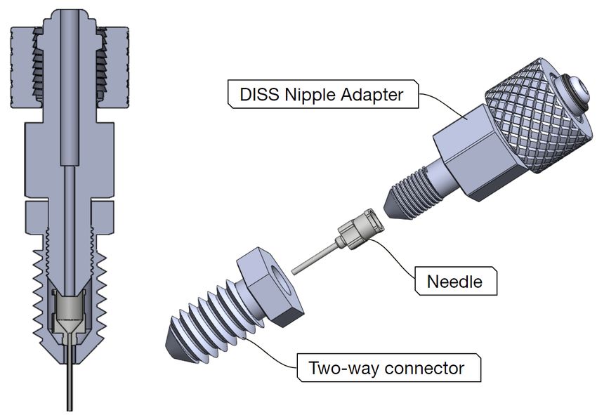
ventilator was found to be very high9 , and accordingly the Bangladesh COVID-19 guidelines recommend trying to avoid
intubation at all costs5 .
In recent times, HFNO devices have been found to be effective in treating hypoxemic COVID-19 patients while reducing
the need for mechanical ventilation10, 11 . Although the use of CPAP and BiPAPs are debated for COVID-199 , studies have also
shown the effective use of CPAPs to reduce ICU demand and mortality12, 13 . One study concluded that, using HFNO vs NIPPV
for critical COVID-19 patients did not yeild significantly differnt outcomes in terms of intubation rate and mortality14 . While
WHO guideline1 does not specifically mention an exact sequence of intermediate therapies (HFNO and NIPPV) to administer
before intubation, the United Kingdom National Health Service (NHS) guidelines particularly mention the preference of NIPPV
over HFNO15 . According to the NHS guidelines, non-invasive ventilation (NIV) may be used as (i) a ceiling of treatment,
(ii) trial to avoid intubation, or (iii) to facilitate extubation. Non-invasive ventilation (e.g., a CPAP) effectively unloads the
respiratory muscle, increases the tidal volume, decreases diaphragmatic work of breathing, and thus reduces hypoxia by
maintaining a PEEP. A device capable of providing a high enough flow while maintaining the PEEP ensures that the patient
receives a sufficient amount of oxygen, prevents the alveoli from collapsing while recruiting new alveoli for respiration16 .
However, the risk of aerosolization is well known for CPAP and BiPAP therapies when using traditional vented masks17 . This
risk can be minimized by using oxygen hood/helmet-based delivery or by using a negative-pressure room18–20 . In21 , it was
hypothesized that two distinct phenotypes, L and H exists for the COVID-19 respiratory failure. The “Type H" respiratory
failure, characterized by more extensive consolidation and high lung elastance, is more responsive to a high Positive End
Expiratory Pressure (PEEP)19 .
In the context of LMICs, various limitations and resource contraints must be taken into account while deciding the most
effective clinical treatment pathway. Although HFNO devices are effective, they are expensive (above $5,000 for reputable
brands) and difficult to import. Due to a lack of regulation, local suppliers may ask for more than double the original price
of the machines. In this situation, the use of low-cost CPAP devices as an intermediary treatment maybe considered in order
to avoid intubation5, 15 . Since CPAP is an aerosol generating procedure2 , either negative-pressure room or non-vented CPAP
masks or oxygen hoods / helmets need to be used. Since the non-vented CPAP masks are low cost and more readily available
for purchase in the market, this is a viable option in the context of Bangladesh. Hence, we propose to develop a low-cost CPAP
system "Oxyjet CPAP" suitable for use in LMIC settings.
2 OXYJET CPAP System
OxyJet CPAP is a low cost CPAP system developed with an aim of early intervention and preventing patients from going to the
ICU. Almost all of its components are off the shelf, except the OxyJet flow generator. The OxyJet flow generator is a pressure
driven flow generator which functions on the basis of jet mixing principle and deliver a continuous flow of oxygenated air to the
patient and maintains a positive pressure inside the patient’s mask. The overall system has the following features:
• Simple and easy to use
• Works without electric power
• Compatible with standard oxygen flowmeter ports
• Non-vented CPAP mask/hood with viral filter minimizes aerosol generation and contamination in the hospital
• Provide high flow of up to 61 L/min
• Provide positive end expiratory pressure (PEEP) between 5 - 20 cm H2 O
• Dual oxygen flowmeters can provide a fraction of inspired oxygen (%FiO2 ) of up to 100%
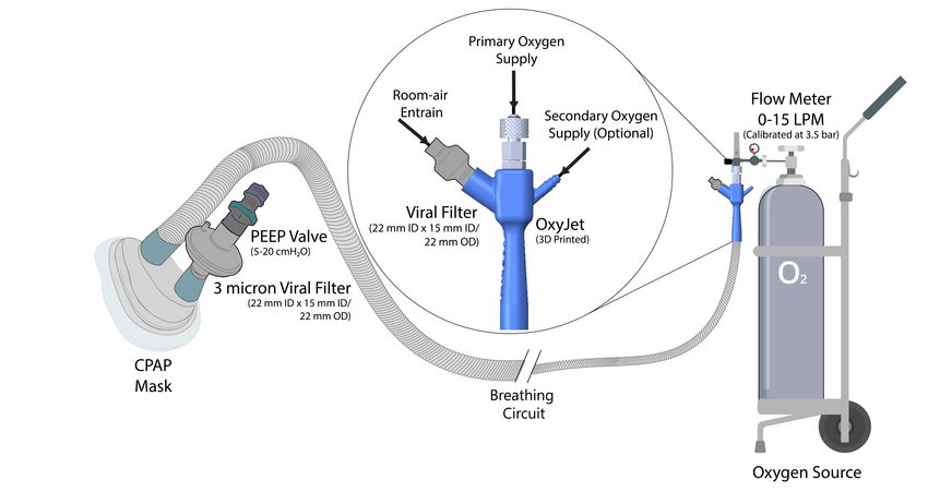
2.1 Device Operation
The oxyjet flow generator is attached to an oxygen source securely with a DISS connector. The flow generator consists of three
inlets: (i) primary oxygen inlet, (ii) air inlet, and (iii) secondary oxygen inlet as shown in Fig 1. When pressurized oxygen is
supplied through the primary inlet it gains high-velocity as it passes through a fine nozzle. This driving flow entrains room air
through the air inlet. Inside the device, the room air is mixed with the high-velocity oxygen and an oxygenated high-flow of air
is channeled through the breathing circuit. The viral filter at the air inlet filters out viruses and dust particles of the entrained
room air. A tightly fitted face mask (non-vented) or helmet minimizes aerosolization. The viral filter at the exhalation port
decontaminates expiratory air. The adjustable PEEP valve maintains a fixed positive end expiratory pressure (5-20 cm H2 O) as
required by patients. A flowchart of the CPAP system is shown in Fig. 2.
2/14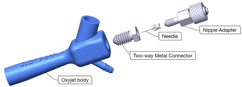
Figure 1. OxyJet CPAP System Overview. The Oxyjet flow generator readily attaches with a standard flowmeter (15L/min).
The air inlet of the flow generator is protected with a viral filter. The secondary oxygen inlet of the flow generator enables
supply of additional oxygen from a secondary flowmeter (50L/min) to increase the oxygen concentration up to 100%. The
outlet of the flow generator is attached to a long breathing circuit at one end and the inhalation port of patient interface
(face-mask or helmet) at the other end. The exhalation port of the patient interface is connected to a viral filter followed by a
PEEP valve.

2.2 OxyJet Flow Generator
Oxyjet flow generator is a specially designed gas ejector (Fig 3), produced from locally available materials, to minimize manu-
facturing complications without hampering the device performance. The flow generator comprises of four main components,
a DISS nipple adapter with a metal knob, a primary nozzle (needle), a specially designed two-way metal connector, and the
oxyjet body.

2.2.1 Primary Nozzle (needle)
It is the heart of the flow generator. It utilizes high pressure of the O2 source to accelerates the driving flow to a sonic/supersonic
condition. There are several important considerations while designing and developing the primary nozzle. The nozzle has to
withstand high pressure (3.5 bar or 50 psi) of the O2 source. The nozzle has to be reproducible with high precision, as a slight
deviation can abruptly change the device performance. Material of the nozzle is also important, since the nozzle has to come in
direct contact with the O2 and air inhaled by patients.
     Taking all these into consideration, design and development of the primary nozzle would be a challenging task in a low
resource facility. Thus, we came up with the idea of repurposing an industrial grade blunt tip stainless steel dispensing needle
as the primary nozzle (Fig 4). The needles can withstand high pressure upto 100 psi (from specification)22 , which is twice the
maximum pressure supplied by the O2 source. The needles are off the shelf and are manufactured with high precision, with
little to no deviation in their inner diameter23 , this solves the reproducibility issue . Moreover, the needles are made of stainless
steel or nickel plated brass22 , which are ideal materials of the oxygen therapy delivery system24 . Thus, the needles fulfill all of
the important considerations.
     Finally, we have to test the performance of these needles with different gauges and the flow generator itself to evaluate
the feasibility of our concept and determine the optimum gauge. We have performed one-dimensional flow analysis and
computational fluid dynamics (CFD) simulations to determine needle gauges that suit our device requirements.
     For one-dimensional isentropic flow, the local pressure, temperature and density is related to their corresponding values at

                                                                                                                                  3/14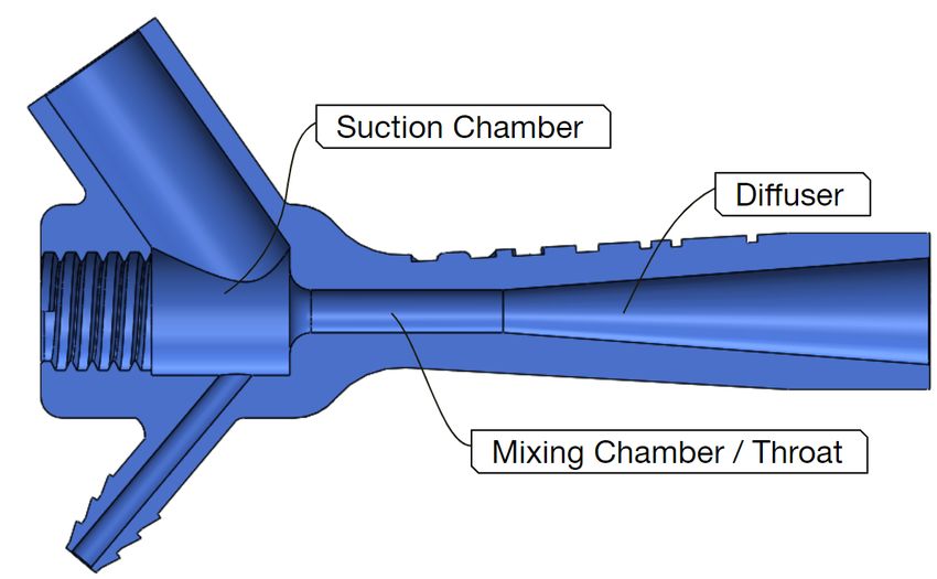
Figure 2. A schematic diagram of the OxyJet CPAP breathing circuit.

            (a)                                                               (b)

                      Figure 3. Illustrations of (a) the oxyjet flow generator and (b) its exploded view.

stagnation condition by the following relations.

                     γ
      p0      γ − 1 2 γ−1
         = 1+      M                                                                                                 (2.2.1.1)
      p         2


      T0      γ −1 2
         = 1+     M                                                                                                  (2.2.1.2)
      T         2

                     1
      ρ0      γ − 1 2 γ−1
         = 1+      M                                                                                                 (2.2.1.3)
      ρ         2
    Now, using the relation (2.1.1) we have compute the minimum stagnation pressure required across any needle gauge for
choked flow (M=1), which is p0 = 191801.05 Pa or 1.918 bar (for the value of γ = 1.4 and local pressure p = 1 atm or 101325
Pa). Hence, any stagnation pressure greater than 1.918 bar (absolute) across a nozzle should be enough to produce choked flow.
    In our device setup, we have used the existing standard pressure regulator and flowmeter arrangements that come with the
O2 source. The maximum operating point of these standard flowmeters are 15 L/min (measurable) flowrate of pure oxygen and
3.5 bar or 50 psi stagnation pressure.

                                                                                                                         4/14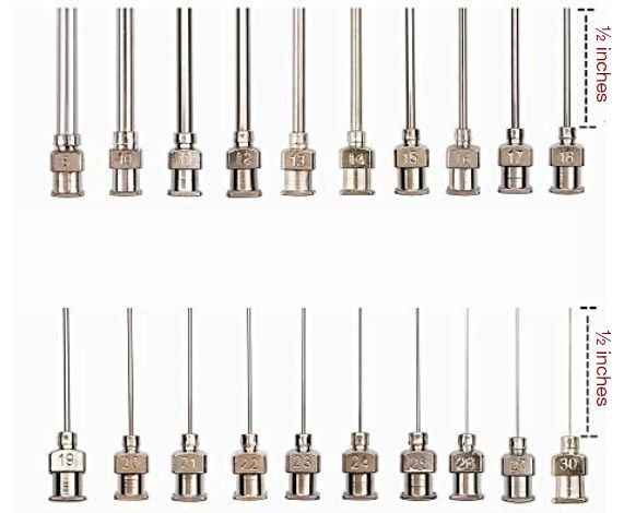
(a)                                    (b)

    Figure 4. Illustration of (a) an industrial grade blunt tip stainless steel dispensing needle and (b) it’s varying gauges

   Using the equation (2.1.4), we have performed some analysis to determine the choked flow rate through nozzles for
one-dimensional isentropic condition with the maximum operating point of the O2 source at inlet.

                 v
                 u       γ+1
           p0 A∗ t γ 2
                 u         γ−1
      ṁ = √                                                                                                            (2.2.1.4)
              T0 R γ + 1

Using the choked flow equation (2.2.1.4), a relation (2.2.1.5) can be derived between flow rate (at SLPM) and needle gauge (G).

                                          v
                                          u         γ+1
                                    p   A∗ γ    2
                                          u           γ−1
                             ∗ ∗ ∗   0
       ṁ = ρsl pm Qsl pm = ρ u A = √
                                          t
                                       T0   R γ + 1

                      v
                         πd 2
                        u        γ+1
                p0      u
                        tγ4  2     γ−1
      Qsl pm =       √                                                                                                  (2.2.1.5)
               ρsl pm T0 R γ + 1

                                2
    Where A∗ = At = πd4 at critical condition and "d" is the inner diameter of a needle labeled with gauge (G).
    We have also performed some Computational Fluid Dynamics (CFD) analysis and compared with our theoretical findings.
Fig 5, illustrates the comparison of the maximum allowable flow (choked flow) vs needle gauge derived using equation (2.1.5)
and CFD analysis, with the boundary conditions: stagnation pressure p0 = 3.5 bar or 50 psi (gauge) and stagnation temperature
T0 = 300K. In contrast to the one-dimensional isentropic theoretical analysis, three dimensional turbulence, viscous flow with
wall roughness was assumed for the CFD simulations. SST-kw was used as the turbulence model.
    Fig 6 illustrates the CFD simulation result of the variation of center-line absolute pressure and center-line velocity with
distance for needles with different gauges (G16, G17, G18 and G19).
    In the next step, we have evaluated the pressure drop across needles with different gauges, for a fixed inlet flow of 15 L/min
and inlet stagnation temperature T0 = 300K using one-dimensional flow analysis and CFD simulation. Fig 7 illustrates the
CFD simulation result of the variation of center-line absolute pressure and center-line velocity with distance for needles with
different gauges (G16, G17, G18 and G19).
    The needles with gauge 17 and 16 produces subsonic compressible flow (Mach number < 1) whereas the needles with
gauge 19 and 18 produces supersonic flow. As the needle gauge increases, the inlet stagnation pressure increases. The gauge
pressures are 3.85 bar, 2.2 bar, 0.94 bar and 0.59 bar for needles with gauge 19, 18, 17 and 16 respectively. Moreover, pressure
drops sharply at the needle exit with oscillation (shock diamond) for needles with gauge 19 and 18. However, no sharp fall of
pressure or pressure oscillation (shock diamond) is observed in case of needles with gauge 17 and 16. The needle exit velocity
also increases with needle gauge. Moreover, there is a sharp increase in velocity at the nozzle exit and presence of oscillation
(shock diamond) for needles with gauge 19 and 18. However, the needle exit velocity remains subsonic compressible for
needles with gauge 17 and 16. Hence, the required inlet stagnation pressure for needles with gauge equal or higher than 18 can

                                                                                                                             5/14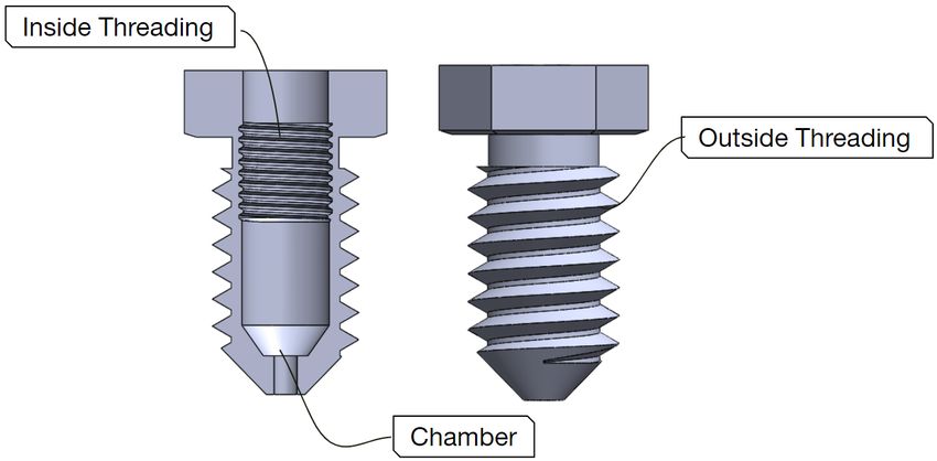
Theoretical         CFD Simulation

                                        70
                                        65
                                        60
                                        55
                                        50
                                        45
                                        40

                            Q (SLPM)
                                        35
                                        30
                                        25
                                        20
                                        15
                                        10
                                         5
                                         0
                                             15   16   17             18          19        20   21    22

                                                                     Needle Gauge (G)

Figure 5. Maximum allowable flow (SLPM) vs Needle gauge for p0 = 3.5 bar and T0 = 300K.The CFD simulation results are
in close agreement with one-dimensional flow analysis. However, the CFD simulation curve is always below the
one-dimensional flow curve, which is acceptable because CFD simulation takes many factors (like viscosity, wall roughness
etc) into consideration.

                                       (a)                                                            (b)

Figure 6. Comparison of the variation of (a) center-line absolute pressure and (b) center-line velocity with distance for
needles with different gauges. Y=0 mm indicates needle exit. CFD simulations include ambient environment at the needle exit.
All the needle gauges produce similar curves. The supersonic under-expanded nozzle flow causes sharp pressure drop at the
needle exit and produces shock diamond. The amplitude of the pressure oscillation at the needle exit increases as the needle
gauge decreases.The center-line velocity curves indicate that decrease in pressure is accompanied by increase in velocity.
Velocity oscillations are also observed in the shock diamond and there is a subsequent decrease in velocity as the jet diffuses.
However, the amplitude of the velocity oscillation and the length of the region before the start of jet diffusion increases as the
needle gauge decreases. Needles of lower gauges produce jets having larger diameter.

be determined using the one-dimensional isentropic flow equation (2.1.5) directly. However, for the needle with gauge lower
than 18, which produces subsonic compressible flow we have to deduce an equation from the continuity equation:

      ṁ = ρAu = ρAMc
            P        P   p                                                                                              (2.2.1.6)
         =    AMc =    AM γRT
           RT       RT
   Using equation (2.2.1.2) and (2.2.1.6) we can deduce

                2       2ṁ2 RT0
       M4 +        M2 − 2 2         =0                                                                                  (2.2.1.7)
              γ −1     P A γ(γ − 1)

                                                                                                                             6/14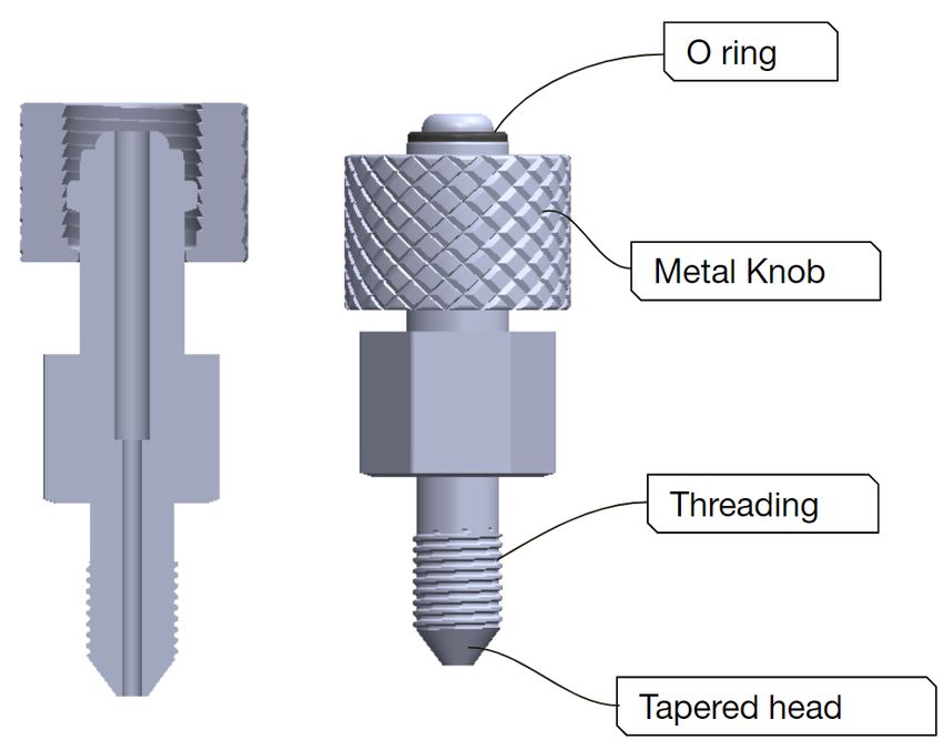
(a)                                                             (b)

Figure 7. Comparison of the variation of (a) center-line absolute pressure and (b) center-line velocity with distance for
needles with different gauges. For a fixed flowrate (15 SLPM), the center-line absolute pressure and center-line velocity
variation curves are different for needles with different gauges.

Solving the equation (2.1.7) for needles with gauge lower than 18 with the boundary conditions: stagnation temperature T0 =
300K and flowrate = 15 SLPM we can determine the real value of mach number M. Now, using the equation (2.1.1) we can
determine the stagnation pressure p0 .
    Fig 8 illustrates the comparison of the required stagnation pressure (gauge) at the needle inlet with different gauges derived
from CFD simulation and one-dimensional flow analysis. From graph (Fig 5) it is observed that the needle with gauge 19 is the
closes gauge that operates approximately at the maximum operating point (15 L/min flow) utilizing maximum pressure of the
O2 source. Graph (Fig 8) also supports the above statement. However, as we gradually decrease the needle gauges from G19 to
G18, G17, or G16, the stagnation pressure at needle inlet p0 also decreases for a fixed flowrate (15 LPM) of O2 . (from fig 8).
This suggests that the lower the gauge of the needle, the less it utilizes the pressure delivered by the O2 source.

                                                                               Theoretical         CFD Simulation

                                                              10.0

                                                               9.0
                            Gauge Stagnation Pressure (bar)

                                                               8.0

                                                               7.0

                                                               6.0

                                                               5.0

                                                               4.0

                                                               3.0

                                                               2.0

                                                               1.0

                                                               0.0
                                                                     15   16   17             18          19        20   21    22

                                                                                             Needle Gauge (G)

Figure 8. Comparison of the pressure drop across needle of different needle gauges derived from CFD simulation and
one-dimensional flow analysis with boundary conditions: Flowrate = 15 LPM and T0 = 300K. The CFD simulation results are
in close agreement with the theoretical results. However, the pressure drop curve of the CFD simulation is always above the
one-dimensional flow analysis curve (theoretical) , because CFD simulation takes many factors (like viscosity, wall roughness
etc) into considerations.

    Based on the above analysis we came to several conclusions: i) Needle with gauge 19 utilizes maximum pressure of the O2
source ii) Needle with gauge lower than 19 utilizes less pressure than the pressure delivered by the O2 source and iii) Needle
with gauge G18 and higher attains a supersonic state whereas needle with gauge lower than G18 remains in the subsonic region.
These analysis helped us understand some basic properties of these needles and how they vary with gauges (G19, G18, G17,
and G16).

                                                                                                                                    7/14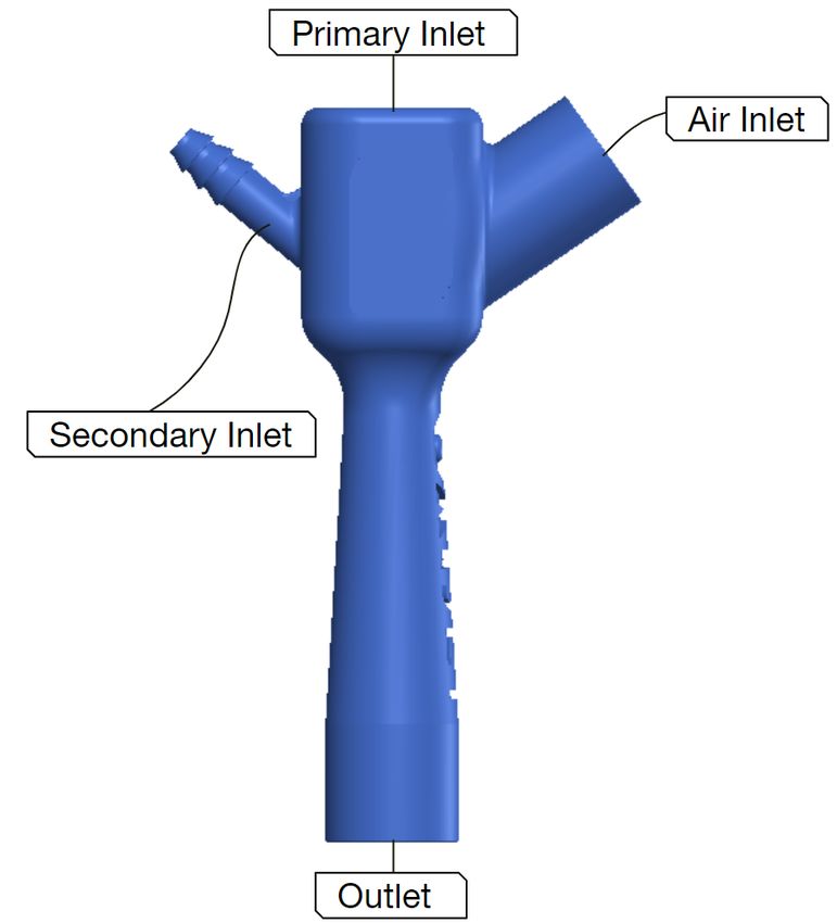
2.2.2 DISS Nipple adapter
DISS Nipple adapter is an off the shelf component. However, there are several types of oxygen connector and we need a
specific type as illustrated in Fig 9. This adapter is used to connect our flow generator directly to any standard flowmeter. The
metal knob at the top is used to attach the adapter with a standard flowmeter and the O-ring ensures no leak. The bottom part of
the adapter has threading on the outside wall and a tapered tip. The tapered tip fits perfectly on the needle hub.

                     Figure 9. Illustration of an off the shelf DISS Nipple adapter and its cross section

2.2.3 Two-way Metal Connector
A custom-made two-way metal connector that has a chamber and inner threading that attaches the needle air-tightly with the
DISS nipple adapter. There is also outside threading that connects the whole arrangement with the Oxyjet body.

                  Figure 10. Illustration of a custom made two-way metal connector and its cross section

2.2.4 Assembled adapters with primary nozzle
Fig 11 illustrates the way a two-way metal connector attaches a needle (primary nozzle) air-tightly with an off the shelf DISS
Nipple adapter.

2.2.5 Oxyjet Body
Oxyjet body is another important component of the flow generator. It utilizes the supersonic driving flow of O2 generated by
the primary nozzle to pull air from the environment and produce an oxygen rich homogeneous high flow. Oxyjet body has three
chambers. The first chamber is the suction chamber, where the primary inlet, the air inlet and any additional secondary inlet
opens up.The high velocity driving flow from the primary inlet creates a low-pressure region which entrains environmental air.
The combined flow then passes through the second chamber (mixing chamber). It is a constant-area chamber where the flows

                                                                                                                            8/14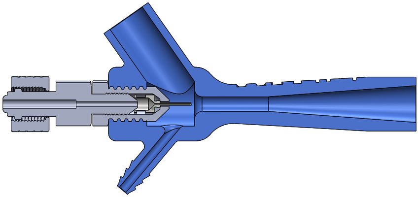
Figure 11. Illustration of exploded and cross-sectional views of Assembled adapters with primary nozzle

mix together to produces a homogeneous high flow. The high flow then passes through the third chamber (diffuser), where
the flow is decelerated to induce pressure recovery. The output flow is oxygen rich homogeneous high flow, and can provide
pressure (PEEP).
    We aimed to make the Oxyjet body simple and 3D printable so that it can be produced with minimum manufacturing
complexity. We started the base design of the Oxyjet body as a typical constant-area gas ejector, with three chambers (suction,
mixing and diffuser chamber), two inlets (primary inlet and air inlet) and one outlet. However, this is a complex 3D structure
and hence required CFD simulations for optimization. In25 LIAO, he performed several CFD simulations on single phase gas
ejector to determine the optimum range of design parameters to achieve the optimal performance. The geometry and dimension
for most cases were maintained within that optimum range. Initially, we optimized the design for the needle with gauge 19
(primary nozzle), having a needle diameter of Dn = 0.686 mm .

                             Figure 12. Illustration of the diagram of a constant-area gas ejector

    In our design (as illustrated in Fig 12), we have used the diameter of the mixing chamber to be Dmc = 6mm. The optimum
range of diameter ratio of mixer to needle Dmc /Dn is between 8 to 1425 . And the diameter ratio of mixer to needle in our case
is Dmc /Dn = 8.75, which is within the optimum range. There has to be a small gap between needle exit and mixing chamber,
which is labeled as Lgap = Lsc − Ln . We have used Lgap = 2.5mm. The optimum range of Lgap /Dmc ratio is between 0.25
to 1.525 . The ratio Lgap /Dmc in our case is 0.42, which is also within the optimum range. For mixer length, we have used
Lmc = 30mm. In reality, the ratio of mixer length to mixer diameter Lmc /Dmc is designed to be within the range of 8 to 12.
However it was shown through CFD analysis, the air entrainment of the ejector decreases with the increase in Lmc /Dmc 25 . The
ratio Lmc /Dmc in our case is 5, which is less than the suggested ratio. This choice was made to keep the device compact without
hampering the performance. Finally, we have used the diffuser length to be Ld = 60mm and diffuser outlet diameter to be
Dd = 15mm. The optimum diffuser expansion angle is in the range of 2◦ to 6◦25 . The diffuser expansion angle θd = 4.3◦ in
our case, which is within the optimum range. The geometry details of the oxyjet body optimized for needle with gauge 19 is
illustrated in Table 1.
    Maintaining the important geometry parameters within the optimum range we have modified other parts of the oxyjet body
to make it a single piece 3D printable design. We have inclined the air inlet to an angle of 55◦ and set it’s inner diameter to 16
mm and outer diameter to 22 mm, so that the pulled air can easily flow with the primary jet and we can easily attach a standard
viral filter to the air inlet port. An additional inlet has been added at the suction chamber (first chamber) to supply more O2

                                                                                                                             9/14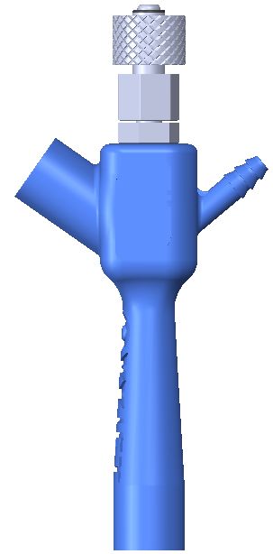
Needle Gauge      Dn (mm)     Ln (mm)    Lgap (mm)     Dmc (mm)     Lmc (mm)    Ld (mm)     Dd (mm)     θd
           19                0.686       12.5       2.5           6            30          60          15          4.3

                       Table 1. Optimized geometry parameters of a gas ejector with needle gauge 19

from a secondary O2 source (via oxygen tube) and increase the %FiO2 (up to 100%) when needed. This secondary inlet was
also inclined to an angle of 50◦ . We have designed the structure of the secondary inlet similar to the outlet of a christmas tree
O2 adapter. These inclinations are important for manufacturing the oxyjet body using 3D printing without support. There is
threading on the inside wall at the primary inlet of the oxyjet body, which is used for the attachment of the primary nozzle
arrangement (Fig 11).

                             (a)                                                              (b)

                       Figure 13. Illustrations of (a) the oxyjet body and (b) its cross-sectional view.

2.2.6 Performance Evaluation of Oxyjet flow generator
The complete oxyjet flow generator is a complex structure having multiple inlets. It is not possible to evaluate it’s perfor-
mance using one-dimensional flow analysis. Hence, we have to use CFD analysis and practical experiments for the device
characterization. Fig 14 illustrates a cross-sectional view of the oxyjet flow generator.
    We have performed experimental analysis with different needle gauges (G20, G19, G18, G17 and G16) to determine the
output flow (L/min) of the flow generator at open circuit condition as illustrated in Fig 15. However, the primary O2 flow
(L/min) (i.e. driving flow) passing through the needles are not the same for all gauges. This is because of the upper limits
(15L/min flow and 3.5 bar or 50 psi stagnation pressure) of a standard flowmeter. When attached to a standard flowmeter, the
primary O2 flow (L/min) passing through the needles with gauges G20, G19 and G18, attains supersonic state. However, for
needles with gauges G17 and G16, the flow remains in the subsonic compressible region (based on analysis of Fig 7). The
output flow (L/min) of the oxyjet flow generator is highest (135 L/min) for G18 needle. This is because, the choked flow
(L/min) passing through G18 needle is maximum. For higher needle gauges (G19 and G20), the choked flow (L/min) decreases,
resulting in a decrease in total output flow (L/min). For lower needle gauges (G17 and G16), the flow remains in the subsonic
compressible region which also results in a drastic decrease in the total output flow (L/min).
    In the next step, we have evaluated the variation of output flow (L/min) of the flow generator with PEEP (cm H2 O) for
different needle gauges as illustrated in Fig 16. The output flow (L/min) decreases almost linearly with increasing PEEP for all
needle gauges. The curve for G18 needle is above all, maintaining an output flow of 135 L/min and 118 L/min at 0 and 20 cm
H2 O PEEP respectively. The curve for G16 needle is below all, maintaining an output flow of 61L/min and 33 L/min at 0 and
20 cm H2 O PEEP respectively. The curves of other needle gauges are in-between.

                                                                                                                            10/14
Figure 14. Illustration of the cross-sectional view of the oxyjet flow generator
140
130
120
110
100
Flow (L/min)
G20
90
G19
80
G18
70
G17
60 G16
50
40
15 16 17 18 19 20 21
Needle Gauge (G)
Figure 15. Illustration of total output flow (L/min) of oxyjet flow generator for different needle gauges at open circuit
condition.
Based on experimental analysis we conclude: i) The flow generator can generate an output flow of 135 L/min with G18
needle at open circuit condition, which is it’s highest flow ii) We can change the maximum output flow (L/min) of the flow
generator by switching needle gauges.i) The flow generator can deliver pressurized high flow (upto 20 cmH2 O PEEP) for all
experimented needle gauges (G16, G17, G18, G19 and G20) iii) Flow generator with G16 needle delivers an output flow of 61
L/min at open circuit condition and 33 L/min at 20 cm H2 O PEEP. Hence, flow generator with needle gauge lower than G16
should not be used in an early CPAP device, because the output flow lower than this will be insufficient.
By now, we know the characteristic curves of the oxyjet flow generator and how its properties changes with needle gauges.
Our next target is to minimize the oxygen consumption of the device. Minimizing oxygen consumption/waste is very important
especially, for developing countries where there is a shortage of oxygen. Now, to do so, we need to lower the total output flow
(L/min) of the flow generator so that we can increase %FiO2 of the total flow with less amount of O2 flow (L/min). However,
the total flow should not drop below the minimum requirements of early-stage COVID or hypoxemic patients.
From the curves as illustrated in Fig 16 we can conclude, flow generator with G16 needle has the minimum oxygen
consumption compared to other needle gauges and also fulfills minimum flow requirement criteria of early-stage COVID or
hypoxemic patients. Hence, Flow generator with G16 needle is the viable choice for an early CPAP device in LMIC settings.
We have performed further experimental analysis to evaluate the oxygen consumption of the flow generator with G16
needle. Fig 17 illustrates the maximum output flow (L/min) and minimum oxygen (%FiO2 ) delivered by the oxyjet flow
generator with G16 needle at different PEEP (cm H2 O). At open circuit condition, the maximum output flow and the minimum
oxygen (%FiO2 ) of the flow generator are 61 L/min and 40% respectively. The output flow decreases and the minimum oxygen
11/14140
130
120
110
100
Flow (L/min) 90
80 G20
70 G19
60 G18
50 G17
40 G16
30
20
0 5 10 15 20
PEEP (cm H2O)
Figure 16. Illustration of variation of total output flow (L/min) of the the oxyjet flow generator with PEEP (cm H2 O) for
different needle gauges.
(%FiO2 ) increases almost linearly with PEEP (cm H2 O). At 20 cm H2 O PEEP, the output flow and the minimum oxygen
(%FiO2 ) reach 33 L/min and 57% respectively.
Flow (L/min) %FiO2
65 60
60
55
55
50 50
Flow (L/min)
45
% FiO2
45
40
35 40
30
35
25
20 30
0 5 10 15 20
PEEP (cm H2O)
Figure 17. Illustration of the maximum output flow (L/min) and minimum oxygen (%FiO2 ) delivered with PEEP (cm H2 O)
by the oxyjet flow generator with G16 needle.
Fig 18 illustrates the oxygen consumption of the flow generator with G16 needle at different settings. For different PEEP
(cm H2 O) setting, the %FiO2 follows a linear relation with the supplied oxygen flow (L/min) having different intercept and
slope. At 0 cm H2 O PEEP, the flow generator can provide 100% oxygen concentration (%FiO2 ) using 61 L/min of supply
oxygen via dual channel flowmeters (15L/min + 50 L/min). As the PEEP increases and the total output flow decreases, the
amount of supply oxygen (L/min) to provide 100% oxygen concentration (%FiO2 ) also decreases.
3 Conclusion
This paper describes the design and preliminary evaluation of the Oxyjet CPAP system, particularly the flow-generator design.
This is an ongoing project and this paper discloses an initial version of the design and evaluation of this device. Due to the
12/14100
95
90
85
80
75
70 33 L/min (20 cm H2O)
65 42 L/min (15 cm H2O)
% FiO2
60 49 L/min (10 cm H2O)
55 54 L/min ( 5 cm H2O)
50 61 L/min ( 0 cm H2O)
45
40
35
30
25
12
14
16
18
20
22
24
26
28
30
32
34
36
38
40
42
44
46
48
50
52
54
56
58
60
Supply oxygen flow (L/min)
Figure 18. Illustration of the oxygen consumption of the flow generator with G16 needle at different settings.
pandemic and the need for low-cost oxygen delivery systems, we have made the decision to publish this pre-print and open
our design for public use. However, we will continue to further develop and improve the device based on the ongoing clinical
evaluation of the device.
4 DISCLAIMER
The OxyJet device design provided in this paper is an medical device prototype. It is not approved by any medical device
regulatory authority and should not be used in the hospital without proper approval. Clinical evaluations of the device is
currently ongoing using this device in Bangladesh with the approval of Bangladesh Medical Research Council (BMRC). The
authors provide the design and evaluation data in this manuscript as is, and do not take responsibility for the failure of the
device if manufactured by any one by using the designs provided herewith. If it is to be manufactured for medical use or clinical
trials, it should be appropriately tested and evaluated according to the regulatory requirements that may apply.
5 ACKNOWLEDGMENT
We would firstly like to thank the Department of Biomedical Engineering (BME), BUET for supporting this research by
providing laboratory access throughout the lockdown period. We would specifically thank Prof. Dr. Aynal Haque, Dr. Tarik
Arafat and Dr. Jahid Ferdous. We are also grateful for the support of the BUET administration, specifically, Prof. Dr. Satya
Prasad Majumder. We have had extensive discussions with medical doctors to understand the requirements of a CPAP device
for Covid-19 patients. Among them, we would like to thank Dr. Abdullah Al Ahmed, Dr. Fuad Galib, Prof. Dr. Robed Amin,
Dr. Forhad Uddin Hasan Choudhury, Dr. Khairul Islam and Dr. Mohiuddin Sharif.
References
1. W H O. Clinical management of COVID-19: interim guidance, 27 May 2020. Tech. Rep., World Health Organization
(2020).
2. Whittle, J. S., Pavlov, I., Sacchetti, A. D., Atwood, C. & Rosenberg, M. S. Respiratory support for adult patients with
COVID-19. J. Am. Coll. Emerg. Physicians Open 1, 95–101 (2020).
3. Rhodes, A. et al. Surviving sepsis campaign: international guidelines for management of sepsis and septic shock: 2016.
Intensive care medicine 43, 304–377 (2017).
4. Rimensberger, P. C., Cheifetz, I. M., Group, P. A. L. I. C. C. et al. Ventilatory support in children with pediatric acute
respiratory distress syndrome: proceedings from the pediatric acute lung injury consensus conference. Pediatr. Critical
Care Medicine 16, S51–S60 (2015).
13/145. Directorate General of Health Services (DGHS). National Guidelines on Clinical Management of Coronavirus Disease
2019 (COVID-19). Tech. Rep., Ministry of Health & Family Welfare, Government of the People’s Republic of Bangladesh
(2020).
6. Mollah, S. & Saad, M. Crisis of Oxygen Cylinders: Demand sky high, prices too (2020).
7. Abdullah, M. Number of ICU beds insufficient to combat Covid-19 pandemic (2020).
8. Forbes. The countries with the most critical care beds per capita [infographic]. https://www.forbes.com/sites/
niallmccarthy/2020/03/12/the-countries-with-the-most-critical-care-beds-per-capita-infographic/#317ad40c7f86. (Ac-
cessed on 08/05/2020).
9. Ñamendys-Silva, S. A. Respiratory support for patients with COVID-19 infection. The Lancet Respir. Medicine 8, e18
(2020).
10. Rochwerg, B. et al. Official ERS/ATS clinical practice guidelines: noninvasive ventilation for acute respiratory failure.
Eur. Respir. J. 50 (2017).
11. Slessarev, M., Cheng, J., Ondrejicka, M. & Arntfield, R. Patient self-proning with high-flow nasal cannula improves
oxygenation in COVID-19 pneumonia. Can. J. Anesth. canadien d’anesthésie 1–3 (2020).
12. Lawton, T. et al. Reduced ICU demand with early CPAP and proning in COVID-19 at Bradford: a single centre cohort.
medRxiv (2020).
13. Ashish, A. et al. Early CPAP reduced mortality in covid-19 patients. Audit results from Wrightington, Wigan and Leigh
Teaching Hospitals NHS Foundation Trust. medRxiv (2020).
14. Duan, J. et al. Use of high-flow nasal cannula and noninvasive ventilation in patients with COVID-19: A multicenter
observational study. The Am. J. Emerg. Medicine (2020).
15. NHS, B. Guidance for the role and use of non-invasive respiratory support in adult patients with coronavirus (confirmed or
suspected) 2020 26 March 2020 Version 2. Publ. approval reference 1559 (2020).
16. András Lovas, D. T., Márton Ferenc Németh & Molnár, Z. Lung Recruitment Can Improve Oxygenation in Patients
Ventilated in Continuous Positive Airway Pressure/Pressure Support Mode. [Updated 2015 Apr 21]. Front Med (Lausanne)
(Publishing; 2015 Apr 21.).
17. Simonds, A. et al. Evaluation of droplet dispersion during non-invasive ventilation, oxygen therapy, nebuliser treatment and
chest physiotherapy in clinical practice: implications for management of pandemic influenza and other airborne infections.
Heal. technology assessment (Winchester, England) 14, 131–172 (2010).
18. Ing, R. J. et al. Role of Helmet-Delivered Noninvasive Pressure Support Ventilation in COVID-19 Patients. J. Cardiothorac.
Vasc. Anesth. (2020).
19. Marini, J. J. & Gattinoni, L. Management of COVID-19 respiratory distress. Jama (2020).
20. Radovanovic, D. et al. Helmet CPAP to treat acute hypoxemic respiratory failure in patients with COVID-19: a management
strategy proposal. J. clinical medicine 9, 1191 (2020).
21. Gattinoni, L. et al. COVID-19 pneumonia: different respiratory treatments for different phenotypes? (2020).
22. Stainless steel dispensing needles - specification. https://www.vapebureau.com.au/products/
85mm-stainless-steel-dispensing-needles-8-10-12-gauge.
23. Birmingham gauge. https://en.wikipedia.org/wiki/Birmingham_gauge.
24. Solutions, E. A. Material guidelines for gaseous oxygen service. https://www.emerson.com/documents/automation/
product-bulletin-material-guidelines-for-gaseous-oxygen-service-en-141422.pdf (2017).
25. LIAO, C. Gas ejector modeling for design and analysis. Ph.D. Diss. Nucl. Eng. Dept., Tex. A&M Univ., Coll. Station. TX
(2008).
14/14You can also read