Service Handbook COMMERCIAL GAS HIGH EFFICIENCY WATER HEATERS - Lochinvar
←
→
Page content transcription
If your browser does not render page correctly, please read the page content below
Service Handbook
                                   COMMERCIAL GAS HIGH EFFICIENCY WATER HEATERS

                                                                                FOR MODELS:
                                                        Charger 120 thru 400(A), Series 118/119

                                            INSTALLATION CONSIDERATIONS - PRE SERVICE CHECKS -
                                         CONSTRUCTION - OPERATION & SERVICE - TROUBLESHOOTING

               SERVICING SHOULD ONLY BE PERFORMED BY A QUALIFIED SERVICE TECHNICIAN

PRINTED 1219                                                            100324833 2000580441 Rev A
CONTENTS
INTRODUCTION.............................................................3 The Eliminator (Self-Cleaning System)..................... 10
Qualifications.............................................................. 3 Automatic Flue Damper............................................. 10
INSTALLATION CONSIDERATIONS..............................4 Uncrating................................................................... 10
Instruction Manual...................................................... 4 GAS CONTROL VALVE................................................11
Closed Water Systems............................................... 4 White Rodgers Integrated Temperature Control-High
Thermal Expansion..................................................... 4 Limit Switch............................................................... 12
Air Requirements........................................................ 4 SEQUENCE OF OPERATION FLOW CHART..............14
Contaminated Air........................................................ 4 TROUBLESHOOTING CHECKLIST.............................15
VENTING.........................................................................5 GENERAL SERVICE CHART.......................................16
GAS SUPPLY SYSTEMS................................................7 FAULT AND WARNING CODES...................................17
Supply Gas Regulator................................................ 7
WIRING DIAGRAM ......................................................28
Gas Piping.................................................................. 8
PURGING................................................................... 9 NOTES..........................................................................29
FEATURES AND COMPONENTS................................10 NOTES..........................................................................30
2 Servicing should only be performed by a Qualified Service TechnicianINTRODUCTION
This Service Handbook covers the water heater Model and Series numbers listed on the front cover only. The instructions and
illustrations contained in this service handbook will provide you with troubleshooting procedures to verify proper operation and
diagnose and repair common service problems.
QUALIFICATIONS
Qualified Installer or Service Agency
Installation and service of this water heater requires ability equivalent to that of a Qualified Agency (as defined by ANSI below) in
the field involved. Installation skills such as plumbing, air supply, venting, gas supply and electrical supply are required in addition
to electrical testing skills when performing service.
ANSI Z223.1 2006 Sec. 3.3.83: “Qualified Agency” - “Any individual, firm, corporation or company that either in person or through
a representative is engaged in and is responsible for (a) the installation, testing or replacement of gas piping or (b) the connection,
installation, testing, repair or servicing of appliances and equipment; that is experienced in such work; that is familiar with all
precautions required; and that has complied with all the requirements of the authority having jurisdiction.”
Service Warning
If you are not qualified (as defined by ANSI above) and licensed or certified as required by the authority having jurisdiction to perform
a given task do not attempt to perform any of the procedures described in this service handbook. If you do not understand the
instructions given in this service handbook do not attempt to perform any procedures outlined in this service handbook.
Service Reminder
When performing any troubleshooting step outlined in this service handbook always consider the wiring and connectors between
components. Perform a close visual inspection of all wiring and connectors to and from a given component before replacement.
Ensure wires were stripped before being crimped in a wire connector, ensure wires are crimped tightly in their connectors, ensure
connection pins in sockets and plugs are not damaged or worn, ensure plugs and sockets are mating properly and providing good
contact.
Failure to perform this critical step or failing to perform this step thoroughly often results in needless down time, unnecessary parts
replacement, and customer dissatisfaction.
Tools Recommended
• Instruction Manual that came with the water heater.
• All tools common to installation and service of commercial water heaters such as hand tools, screwdrivers, pipe wrenches etc.
• Hex (Allen) wrench sizes: 5/32”, 1/8”, 1/4” and 5/16"
• Digital manometer: Range -20.00 to +20.00" W.C. Resolution - 0.01" W.C. Required to test supply gas pressure.
• Digital Multi Meter; capable of measuring:
• AC/DC Voltage.
• Ohms.
• DC micro amps (μA).
Servicing should only be performed by a Qualified Service Technician 3INSTALLATION CONSIDERATIONS This section of the Service Handbook covers some of the critical installation requirements that, when overlooked, often result in operational problems, down time and needless parts replacement. Costs to correct installation errors are not covered under the limited warranty. Ensure all installation requirements and instructions contained in the Instruction Manual that came with the water heater have been followed prior to performing any service procedures. INSTRUCTION MANUAL Have a copy of the Instruction Manual that came with the water heater on hand for the model and series number being serviced. Installation information given in this Service Handbook is not a complete installation instruction. Installation information given in this Service Handbook has a limited focus as it applies to servicing the water heater. This Service Handbook does not replace or supersede the Instruction Manual that came with the water heater. Always refer to the Instruction Manual for complete installation instructions. If the Instruction Manual is not on hand, copies can be obtained from the manufacturers web site or by calling the technical support phone number shown on the back cover of this Service Handbook. CLOSED WATER SYSTEMS Water supply systems may, because of code requirements or such conditions as high line pressure, among others, have installed devices such as pressure reducing valves, check valves, and back flow preventers. Devices such as these cause the water system to be a closed system. THERMAL EXPANSION As water is heated, it expands (thermal expansion). As the volume of water grows there will be a corresponding increase in water pressure due to thermal expansion. Thermal expansion can cause premature tank failure (leakage). This type of failure is not covered under the limited warranty. Thermal expansion can also cause intermittent Temperature-Pressure Relief Valve operation: water discharged from the valve due to excessive pressure build up. This condition is not covered under the limited warranty. The Temperature-Pressure Relief Valve is not intended for the constant relief of thermal expansion. A properly sized thermal expansion tank must be installed on all closed systems to control the harmful effects of thermal expansion. Contact a local plumbing service agency to have a thermal expansion tank installed. AIR REQUIREMENTS Carefully review the requirements for combustion and ventilation air in the Instruction Manual that came with the water heater. Failure to meet these requirements when the water heater is installed or overlooking their importance when servicing the water heater often results in needless down time, unnecessary parts replacement, and customer dissatisfaction. An inadequate supply of air for combustion and ventilation can cause recirculation of combustion products resulting in contamination that may be hazardous to life. Such a condition often will result in a yellow, luminous burner flame, causing sooting of the combustion chamber, burners and flue tubes and creates a risk of asphyxiation. CONTAMINATED AIR Combustion air that is contaminated can greatly diminish the life span of the water heater and water heater components such as hot surface igniters and burners. Propellants of aerosol sprays, beauty shop supplies, water softener chemicals and chemicals used in dry cleaning processes that are present in the combustion, ventilation or ambient air can cause such damage. Do not store products of this sort near the water heater. Air which is brought in contact with the water heater should not contain any of these chemicals. If necessary, uncontaminated air should be obtained from remote or outdoor sources. 4 Servicing should only be performed by a Qualified Service Technician
VENTING
This section of the Service Handbook is not a complete venting installation instruction. Refer to the Instruction Manual that came
with the water heater; ensure the venting has been installed per all Instruction Manual requirements. Costs to correct installation
errors are not covered under the limited warranty.
The instructions in this section on venting must be followed to avoid choked combustion or recirculation of flue gases. Such
conditions cause sooting or risks of fire and asphyxiation.
Heater must be protected from freezing downdrafts. Remove all soot or other obstructions from the chimney that will retard a free
draft.
Type B venting is recommended with these heaters. For typical venting application refer to Technical Data Venting in the Instruction
Manual. This water heater must be vented in compliance with all local codes, the current revision of the National Fuel Gas Code
(ANSI-Z223.1) and with the Category I Venting Tables.
If any part of the vent system is exposed to ambient temperatures below 40°F it must be insulated to prevent condensation.
  • Do not connect the heater to a common vent or chimney with solid fuel burning equipment. This practice is prohibited by many
     local building codes as is the practice of venting gas fired equipment to the duct work of ventilation systems.
  • Where a separate vent connection is not available and the vent pipe from the heater must be connected to a common vent with
     an oil burning furnace, the vent pipe should enter the smaller common vent or chimney at a point above the large vent pipe.

All Charger water heaters are classified by ANSI as category I (non-condensing, negative pressure venting) appliances. They are
approved for Type B venting. For larger applications, Charger water heaters can be common vented together either in a tapered
manifold or constant size manifold. (Follow National Fuel Gas Code requirements for sizing and installation.) Chargers may be
common vented only with other category I appliances. (See venting section in the National Fuel Gas Code).

                              Servicing should only be performed by a Qualified Service Technician                                5
Charger water heaters can be used with power vent
kits for sidewall venting. Lochinvar offers power
vent kits for use on installations with a maximum
of 100 equivalent feet of vent piping. The power
vent kits also use type B vent materials. When
power venting, specific exterior clearances must
be maintained, as outlined in the National Fuel
Gas Code. (NFPA 54, ANSI A223.1, sec 7.8)
Figure 1. Power Vent Kits For Sidewall Venting
6 Servicing should only be performed by a Qualified Service TechnicianGAS SUPPLY SYSTEMS
Low pressure building gas supply systems are defined as those systems that cannot under any circumstances exceed 14” W.C.
(1/2 PSI Gauge). These systems do not require pressure regulation. Measurements should be taken to insure that gas pressures
are stable and fall within the requirements stated on the water heater rating plate. Readings should be taken with all gas burning
equipment off (static pressure) and with all gas burning equipment running at maximum rate (dynamic pressure). The gas supply
pressure must be stable within 1.5” W.C. from static to dynamic pressure to provide good performance. Pressure drops that exceed
1.5” W.C. may cause rough starting, noisy combustion or nuisance outages. Increases or spikes in static pressure during off cycles
may cause failure to ignite or in severe cases damage to appliance gas valves. If your low pressure system does NOT meet these
requirements, the installer is responsible for the corrections.
High Pressure building supply systems use pressures that exceed 14” W.C. (1/2 PSI Gauge). These systems must use field supplied
regulators to lower the gas pressure to less than 14” W.C. (1/2 PSI Gauge). Water heaters require gas regulators that are properly
sized for the water heater input and deliver the rating plate specified pressures. Gas supply systems where pressure exceeds 5 PSI
often require multiple regulators to achieve desired pressures. Systems in excess of 5 PSI building pressure should be designed
by gas delivery professionals for best performance. Water heaters connected to gas supply systems that exceed 14” W.C. (1/2 PSI
Gauge) at any time must be equipped with a gas supply regulator.
All models require a minimum gas supply pressure of 4.5" W.C. for natural gas and 11.0" W.C. for propane gas. The minimum supply
pressure is measured while gas is flowing (dynamic pressure). The supply pressure should never fall below 4.5" W.C. for natural gas
and 11.0" W.C. for propane gas. The supply pressure should be measured with all gas fired appliances connected to the common
main firing at full capacity. If the supply pressure drops more than 1.5” W.C. as gas begins to flow to the water heater then the supply
gas system including the gas line and/or the gas regulator may be restricted or undersized. See Supply Gas Regulator section and
Gas Piping section of this manual. The gas valve on all models has a maximum gas supply pressure limit of 14” W.C. The maximum
supply pressure is measured while gas is not flowing (static pressure).
SUPPLY GAS REGULATOR
The maximum allowable gas supply pressure for this water heater is 14 inches W.C. (3.48 kPa). Install a positive lock-up gas
pressure regulator in the gas supply line if inlet gas pressure can exceed 14 inches W.C. (3.48 kPa) at any time. Regulators must
be sized/used according to manufacturer’s specifications.
If a positive lock-up regulator is required follow these instructions:
1. Positive lock-up gas pressure regulators must be rated at or above the input Btu/hr rating of the water heater they supply.
2. Positive lock-up gas pressure regulator(s) should be installed no closer than 3 equivalent feet (1 meter) and no farther than 8
equivalent feet (2.4 meters) from water heater’s inlet gas connection.
3. After installing the positive lock-up gas pressure regulator(s) an initial nominal supply pressure setting of 7.0” W.C. while the
water heater is operating is recommended and will generally provide good water heater operation. Some addition adjustment
maybe required later to maintain a steady gas supply pressure.
4. When installing multiple water heaters in the same gas supply system it is recommended that individual positive lock-up gas
pressure regulators be installed at each unit.
Servicing should only be performed by a Qualified Service Technician 7GAS PIPING
Contact your local gas service company to ensure that adequate gas service is available and to review applicable installation codes
for your area.
Size the main gas line in accordance with Table below. The figures shown are for straight lengths of pipe at 0.5 in. W.C. pressure
drop, which is considered normal for low pressure systems. Note: Fittings such as elbows, tees and line regulators will add to the
pipe pressure drop. Also refer to the latest version of the National Fuel Gas Code.
Schedule 40 Steel or Wrought Iron Pipe is the preferred material for the gas line of this water heater. It is imperative to follow the
sizing recommendations in the latest version of the National Fuel Gas Code if Corrugated Stainless Steel Tubing (CSST) is used
as the gas line for this water heater.
The heater is not intended for operation at higher than 14.0" W.C.- natural gas, (1/2 pound per square inch gage) supply gas
pressure. Exposure to higher supply pressure may cause damage to the gas valve which could result in fire or explosion. If
overpressure has occurred such as through improper testing of gas lines or emergency malfunction of the supply system, the gas
valve must be checked for safe operation. Make sure that the outside vents on the supply regulators and the safety vent valves are
protected against blockage. These are parts of the gas supply system, not the heater. Vent blockage may occur during ice storms.
Table 1. GAS SUPPLY PIPE LENGTHS (IN FEET)
Maximum Equivalent Pipe Length - Natural Gas Only
Schedule 40 Steel or Wrought Iron Pipe
Input rate
(BTU/HR) 1/2" 3/4" 1" 1 1/4" 1 1/2"
120,000 20 70 200 200 200
154,000 10 40 150 200 200
180,000 - 30 100 200 200
199,000 - 30 90 200 200
250,000 - 20 60 200 200
275,000 - 10 50 200 200
310,000 - 10 40 150 200
366,000 - - 30 100 200
390,000 - - 20 100 200
Fitting Type* Equivalent length in feet
45°Ell 0.7 1.0 1.2 1.6 1.9
90°Ell 1.6 2.1 2.6 3.5 4.0
Tee 3.1 4.1 5.2 6.9 8.0
Natural Gas 0.60 Specific Gravity, 0.50" W.C. Pressure Drop
*Screwed Fittings
It is important to guard against gas valve fouling from contaminants in gas ways. Such fouling may cause improper operation, fire
or explosion.
If copper supply lines are used they must be internally tinned and certified for gas service. Before attaching the gas line, be sure
that all gas pipe is clean on the inside. The instructions in this section on venting must be followed to avoid choked combustion or
recirculation of flue gases. Such conditions cause sooting or risks of fire and asphyxiation.
8 Servicing should only be performed by a Qualified Service TechnicianTo trap any dirt or foreign material in the gas supply line, a sediment trap must be incorporated in the piping (see Figure below).
The sediment trap must be readily accessible and not subject to freezing conditions. Install in accordance with recommendations of
serving gas suppliers. Refer to the latest version of the National Fuel Gas Code.
To prevent damage, care must be taken not to apply too much torque when attaching gas supply pipe to gas valve inlet. Apply joint
compounds (pipe dope) sparingly and only to the male threads of pipe joints. Do not apply compounds to the first two threads. Use
compounds resistant to the action of liquefied petroleum gases.
Be sure the gas meter has sufficient capacity to supply the full rated gas input of the water heater as well as the requirements of
all other gas fired equipment supplied by the meter. If gas meter is too small, ask the gas company to install a larger meter having
adequate capacity.
Figure 2. Gas Piping and Sediment Trap Installation
Fire and Explosion Hazard
Use joint compound or Teflon tape
compatible with propane gas.
Leak test before placing the water
heater in operation.
Disconnect gas piping and main gas
shutoff valve before leak testing.
Install sediment trap in accordance
with NFPA 54.
Any time work is done on the gas supply system perform a leak test to avoid the possibility of fire or explosion.
1. For test pressures exceeding 1/2 psi (3.45 kPa) disconnect the water heater and its Main Gas Shutoff Valve from the gas supply
piping system during testing, see Figure above. The gas supply line must be capped when disconnected from the water heater.
2. For test pressures of 1/2 psi (3.45 kPa) or less, the water heater need not be disconnected, but must be isolated from the supply
gas line by closing the Main Gas Shutoff Valve during testing.
3. Coat all supply gas line joints and connections upstream of the water heater with a non-corrosive soap and water solution to
test for leaks. Bubbles indicate a gas leak. Do not use matches, candles, flame or other sources of ignition for this purpose.
4. Repair any leaks before placing the water heater in operation.
PURGING
Gas line purging is required with new piping or systems in which air has entered.
Purging should be performed per the current edition of NFPA 54 the National Fuel Gas Code.
Servicing should only be performed by a Qualified Service Technician 9FEATURES AND COMPONENTS
THE ELIMINATOR (SELF-CLEANING SYSTEM)
These units include The Eliminator (Self-Cleaning System) installed in the front water inlet. The Eliminator inlet tube can only be
used in the front water inlet connection. Do not install the Eliminator inlet tube in either the top or back inlet water connection. The
Eliminator must be oriented correctly for proper function. There is a marked range on pipe nipple portion of the Eliminator, that must
be aligned with top of inlet spud. A label above the jacket hole has an arrow that will point to marked portion of pipe nipple if the
orientation is correct. If the arrow does not point within the marked range on pipe nipple, adjust the pipe nipple to correct. A pipe
union is supplied with the Eliminator to reduce probability of misaligning the Eliminator accidentally while tightening the connection
to inlet water supply line. Improper orientation of the Eliminator can cause poor performance of heater and can significantly reduce
outlet water temperatures during heavy draws.
Figure 3. The Eliminator May Have 1, 3 or 7 Cross Tubes
AUTOMATIC FLUE DAMPER
All units are equipped with an automatic flue damper that reduces heat loss during the OFF cycles. The automatic flue damper drive
assembly is a field replaceable part and may be obtained by contacting your Lochinvar dealer or local supply house.
Each automatic flue damper drive assembly is equipped with a “Service Switch”, as shown in Figure below.
The “Service Switch” has 2 positions: AUTOMATIC OPERATION and HOLD OPEN DAMPER. For normal operation the switch
should be in the AUTOMATIC OPERATION position.
If there is a problem with the damper the “Service Switch” can be placed in the HOLD OPEN DAMPER position. When the switch
is placed in the HOLD OPEN DAMPER position the damper disc will rotate to the open position and the heater may be used until
vent assembly is repaired or replaced. DO NOT turn the damper disc manually; damage will occur to the drive assembly if operated
manually. Refer to TESTING DAMPER OPERATION section of this manual for additional information.
Figure 4. Flue Damper
UNCRATING
The heater is shipped with the flue damper already installed. The wiring conduit runs from the thermostat to the damper drive cover.
Before turning unit on, check to make sure the wiring conduit is securely plugged into damper drive.
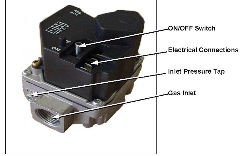
10 Servicing should only be performed by a Qualified Service TechnicianGAS CONTROL VALVE
Figure 6. White-Rogers Gas Valve For Propane (LP)
Figure 5. White-Rogers Gas Valve For Natural Gas
• Inlet screen helps protect from debris.
• Tamper resistant screws.
• Conveniently located ON/OFF switch.
• Inlet and Outlet pressure taps.
• Adjustable gas regulator.
Note: ON/OFF switch must be in the ON position to perform ohm/continuity tests. ON/OFF switch replaced the gas cock on this
new valve design.
Table 2. Gas Pressure Specifications
Natural Propane
Models Charger 120 - 400 Charger 120 - 400
Maximum Gas Supply Pressure 13.8" W.C. 13.8" W.C.
Minimum Gas Supply Pressure 4.5" W.C. 11.0" W.C.
† Pilot Burner Pressure 3.5" W.C. 10.0" W.C.
† Main Burner/ Manifold Pressure 3.5" W.C. 10.0" W.C.
†. Gas pressures given have a tolerance of ± 0.3" W.C.
Servicing should only be performed by a Qualified Service Technician 11WHITE RODGERS INTEGRATED TEMPERATURE CONTROL-HIGH LIMIT SWITCH
The digital thermostat contains the high limit (energy cutout) switch. The high limit switch interrupts main burner gas flow should the
water temperature reach 203°F (95°C).
In the event of high limit switch operation, the water heater cannot be restarted unless the water temperature is reduced to
approximately 120°F (49°C). The high limit reset button on the front of the control then needs to be depressed.
Continued manual resetting of high limit control, preceded by higher than usual water temperature is evidence of high limit switch
operation. The following is a possible reason for high limit switch operation:
• A malfunction in the thermostatic controls would allow the gas control valve to remain open causing water temperature to exceed
the thermostat setting. The water temperature would continue to rise until high limit switch operation.
Contact your dealer or service agent if continued high limit switch operation occurs.
4 Status LEDs
E3 To Upper
Temperature
Probe Temperature
Adjustment
E1 To HSI Dial
Control
12 Pin
Plug Manual
Reset
for ECO
E3 To Lower
Temperature
Probe E2 120
VAC from
Control
Board
3 Amp Automotive Fuse
Figure 7. Digital Thermostat
STATUS LEDS
The Power Status LED is green, ECO, ECO Reset, and Call for Heat Status LEDs are red.
LED STATUS INDICATION ACTION TO TAKE
Power On. Power is On, a call for heat Normal operation.
Call for heat On. currently active.
Power On. ECO has locked out control, tank Check for excessive
ECO On. temperature exceeded 203°F. temperature/ cool down tank.
Power On. Tank temperature has cooled below Press manual reset, determine
Reset On. 120°F after ECO lock out, can be reset. cause for ECO lock out.
12 Servicing should only be performed by a Qualified Service TechnicianElectronic Ignition Control/ Ignition Module
Each heater is equipped with a Honeywell ignition module. The solid state ignition control ignites the pilot burner gas by creating
a spark at the pilot assembly. Pilot gas is ignited and burns during each running cycle. The main burner and pilot gases are cut off
during the OFF cycle. Pilot gas ignition is proven by the pilot sensor. Main burner ignition will not occur if the pilot sensor does not
first sense pilot ignition.
Spark
Connection
LED
Indicators
Figure 8. Ignition Moduel
Continuous Retry for Ignition
90 second trial/ 5 minute off.
Before calling your service agent, the following checklist should be examined to eliminate obvious problems from those requiring
replacement or servicing.
• Check that “main manual gas shut-off valve” is fully open and that gas service has not been interrupted.
• Check that after following the water OPERATING INSTRUCTIONS, the “Top Knob” of the gas control valve is in “ON” position.
• Check electrical supply to the water heater for possible blown (or tripped) fusing or power interruption.
• Is the water temperature in tank below the thermostat dial setting on the thermostat (calling for heat)?
• It is possible that the high limit (E.C.O.) has functioned to shut off the water heater. Contact your serviceman if limit continues to
function to shut off water heater.
Servicing should only be performed by a Qualified Service Technician 13SEQUENCE OF OPERATION FLOW CHART 14 Servicing should only be performed by a Qualified Service Technician
TROUBLESHOOTING CHECKLIST
                                                                                                        REMEDY
        COMPLAINT                             CAUSE
                                                                                   USER                    QUALIFIED SERVICE AGENCY
                                                                          Set thermostat dial to a
                                      Thermostat set too low.
                                                                           higher temperature.
   Water not hot enough.                                                                                    Check continuity and resistance
                                  Upper and/or lower temperature                                              (Ohms) of upper and lower
                                                                       Call qualified service agency.
                                     probe out of calibration.                                               thermostat probes. Replace
                                                                                                             probes if out of specification.
                                                                          Set thermostat dial to a
    Insufficient hot water            Thermostat set too low.
                                                                           higher temperature.
                                                                                                           Check continuity and resistance
                                  Upper and/or lower temperature                                             (Ohms) of upper and lower
                                                                       Call qualified service agency.
                                     probe out of calibration.                                              thermostat probes. Replace
                                                                                                            probes if out of specification.
                                     Main manual gas shutoff          Open main manual gas shutoff
                                      valve partially closed.            valve to fullest extent.

                                                                     Space usage to give heater time
                                   Heater too small for demand.
                                                                      to restore water temperature.

                                                                                                            Check gas input. If incorrect,
                                    Heater recovery is slower.         Call qualified service agency.       adjust gas pressure or replace
                                                                                                                 main burner orifice.
                                      Draft hood not installed                                                Install draft hood or baffles
                                                                       Call qualified service agency.
                                      or one or more baffles.                                                   as furnished with unit.

 Water temperature too hot.          Thermostat set too high.        Set thermostat to a lower setting.

                                     Condensation on outside
Heater makes sounds: sizzling.
                                        of tank - normal.

                                                                     Drain a quantity of water through
                                      Sediment accumulation
          Rumbling.                                                  drain valve. If rumbling persists,              Delime heater.
                                        on bottom of tank.
                                                                      call a qualified service agency.

                                          Expansion and
  Ticking or metallic sounds.
                                        contraction-normal.
                                                                       Drain piping system and refill.
                                     Air chambers in piping
                                                                         Heater must be off while
                                   have become waterlogged.                                                     Follow the manufacturer's
                                                                         this is being done. Check
  Pounding / water hammer.          Thermal expansion tank                                                  instructions for proper charging
                                                                      thermal expansion tank charge
                                  damaged, improperly charged,                                               of the thermal expansion tank.
                                                                         pressure when the water
                                      or improperly sized.
                                                                          system pressure is zero.
                                      Too much primary air.                   Adjust shutters.
     Combustion noises.             Overfired heater. Incorrect
                                      burners or orifice for           Call qualified service agency.       Check and correct as necessary.
                                       types of gas used.
                                                                          If drain valve cannot be
                                   Drain valve not closed tightly.
                                                                           closed tightly, replace.
         Water leaks.               If leakage source cannot be           Shut off gas supply to             Repair or in case of suspected
                                     corrected or identified, call      heater and close cold water        tank leakage, be certain to confirm
                                      qualified service agency.            inlet valve to heater.               before replacing heater.
                                                                                                            Check for sooted flue passage.
         Gas odors.                                                                                         Check for obstructed vent line.
                                                                     Shut off gas supply to heater and
                                        Heater is overfired.                                                Check backdraft or lack of draft.
                                                                       call qualified service agency.
                                                                                                             Draft hood may be improperly
                                                                                                             installed or not sized properly.

                                                                       Shut off gas supply to heater
                                        Possible gas leaks.
                                                                      and call gas company at once.

                                 Servicing should only be performed by a Qualified Service Technician                                           15
GENERAL SERVICE CHART
Condition Cause Solution
DAMPER OPENS NO POWER • DAMPER NOT FULLY OPEN • REPLACE DAMPER.
TO IID MODULE • DEFECTIVE PROTECTOR • REPLACE PC BOARD.
SWITCH
PILOT LIGHTS, SPARKS PILOT FLAME NOT PROVING SEE FLAME RECTIFICATION -
CONTINUOUSLY STEP 8.
HEATER WILL NOT IGNITE NOT PROVING PILOT FLAME INTERRUPT 120 VAC POWER.
EXISTENCE • CHECK GROUND WIRE
ATTACHMENT.
• CLEAN OR REPLACE PILOT
ASSEMBLY.
PILOT GAS NOT COMPLETELY • CHECK SUPPLY GAS
INTERRUPTED AT END OF PRESSURE.
HEATING CYCLE • REPLACE GAS VALVE.
WEEPING TEMPERATURE • THERMAL EXPANSION ADD THERMAL EXPANSION TANK.
AND PRESSURE RELIEF VALVE • FAULTY VALVE REPLACE RELIEF VALVE.
LARGE VOLUME WATER • EXCESSIVE WATER CHECK WIRING REPLACE DUAL
RELIEF FROM T&P VALVE • TEMPERATURE CONTROLLER.
• FAULTY RELIEF VALVE REPLACE RELIEF VALVE.
PREMATURE TANK CONDENSATION • INCREASE STORED WATER
LEAKAGE TEMPERATURE AND CONFIRM
PROPERLY SIZED APPLICATION.
CONTAMINATED AIR • REMOVE CONTAMINANTS.
• SUPPLY CLEAN COMBUSTION
AIR.
WATER HAMMER • ADD WATER HAMMER
ARRESTOR.
• REDUCE WATER PRESSURE.
• REMOVE UNNECESSARY
CHECK VALVES.
THERMAL EXPANSION ADD THERMAL EXPANSION TANK.
DEPLETED ANODES SCHEDULE ANODE CHECKS -
REPLACE AS NEEDED.
DAMPER WILL NOT OPEN BINDING SHAFT SUPPORT VENTING
DAMPER MOTOR • REPLACE DAMPER.
NO SPARK AT PILOT - DAMPER ASSEMBLY SEE STEP 7. Services Switch may
DAMPER FULLY OPEN bypass problem until replacement
part is received.
REPLACE DAMPER .
IID MODULE REPLACE IID STEP 6.
SPARK CABLE REPLACE CABLE STEP 7.
16 Servicing should only be performed by a Qualified Service TechnicianFAULT AND WARNING CODES
Step 1. Troubleshooting The Charger Water Heaters
CHECK/REPAIR:
• Check that 120 VAC is supplied to the heater.
• Make sure the tank is full of water.
• Make sure the gas is supplied to the unit.
Effikal Damper
The wiring colors from the damper PC Board are different colors than the wires on the heater wiring harness. The male/female plugs
to connect the damper board to the heater harness join in only one way.
The heater harness wires still serve the same function:
Servicing should only be performed by a Qualified Service Technician 17HARNESS CHART
Heater Harness Function Damper Harness
Black 24V Hot 1 - Brown
Yellow 24V from Thermostat 2 - Orange
Red 24V from Damper 3 - Yellow
White 24V Common 4 - Black
CONDITION:
• Damper closed.
• High Limit closed.
Flue Damper
Do not turn damper open manually or motor damage will result, use the service switch. All readings are taken from harness
receptacle. Do not push meter leads into harness receptacle. This opens the pins and will create connection problems. See the
following EFFIKAL RVGP-KSF-SERIES FLUE DAMPER TROUBLE SHOOTING GUIDE.
18 Servicing should only be performed by a Qualified Service TechnicianEFFIKAL RVGP-KSF-SERIES FLUE DAMPER TROUBLESHOOTING GUIDE
Do not turn damper open manually or motor damage will result, use the service switch. All readings are taken from harness
receptacle. Do not push meter leads into harness receptacle. This opens the pins and will create connection problems.
Effikal Pinouts & Wire Adapter Wire Colors
Colors Function In
1. Brown 24 VAC HOT Black
PIN END VIEW 2. Orange Signal In Yellow
3. Yellow Signal Out Red
4. Black 24 VAC Common White
NOTE: DAMPER DISC SHOWN IN OPEN POSITION.
WARNING
24 VAC. NORMAL SEQUENCE OF OPERATION
A. FLUE DAMPER OPEN OR OPENING Do not negate
the action of any
(Unit is calling for heat and damper disc should be in vertical position)
existing safety or
VOLTAGE ACROSS: operational controls.
4&1 All Times that High Limit is closed
4&2 Calling for Heat Open or Opening
4&3 During Combustion Damper Open+
B. FLUE DAMPER CLOSED (Unit is not calling for heat and damper disc should be in horizontal position)
NOTE: POSITION 4 IS COMMON AND POSITION 3 IS HOT 24 VAC
VOLTAGE ACROSS
4&1 All Times that High Limit is closed
NO VOLTAGE ACROSS
4 & 3 or 4 & 2 Thermostat not calling for heat.
ABNORMAL OPERATION
A. NOTHING WORKING
NO VOLTAGE ACROSS:
4&1 1. High Limit has tripped and is OPEN. Determine reason for tripping of high limit
2. Bad Transformer
3. Loose or broken connections
4. Blown fuse or circuit breaker
5. Disconnect switch off
6. Harness not plugged into water heater receptacle
B. DAMPER HAS OPENED,
NO COMBUSTION
VOLTAGE ACROSS:
4 & 1; 4 & 2; 4 & 3: 1. Check for power at ignition module terminals. If 24 VAC power is present damper
is working properly.
2. Defective component in water heater after the flue damper.
3. If 24 VAC is not present at the ignition module, look for loose or broken connections
between damper and ignition module.
4. If the connections from damper to ignition module seem proper, replace damper
assembly. If a damper assembly is not available, place the service switch in the
hold open position. This should keep the damper in the open position and allow
the customer to have automatic heat, until a replacement damper can be installed.
C. DAMPER ROTATES Change the entire damper assembly
CONTINUOUSLY
D. DAMPER STICKS 1. Make sure no screws obstruct the damper blade.
2. Make sure damper pipe assembly is not egg shaped.
3. Make sure damper rod is not rubbing on pipe assembly.
4. See figure on front page of this insert sheet
IMPORTANT: DAMPER MUST BE OPEN BEFORE COMBUSTION TAKES PLACE.
Servicing should only be performed by a Qualified Service Technician 19Step 2: Test For 24Vac Between Black And Orange On Damper PC Board
IF THEN
24VAC is present - damper NOT opening • Check Service Switch Position. Replace Damper Assembly.
24VAC is not present. • Check Wiring Harness to Thermostat.
24VAC present - Damper Opens • Continue to Step 3.
CONDITION:
• Damper rotates continuously.
Step 3: Test the Three AMP FUSE
CONDITION:
• Test via the terminals on the head of the fuse or by removing the fuse and testing across the blades.
• Verify that there is 120 VAC to the thermostat. Once verified set the meter to check for continuity and perform the checks
shown in figure below and on next page.
20 Servicing should only be performed by a Qualified Service TechnicianVisually inspect the fuse to see if it is blown, the inside of the fuse can appear dark, discolored and burnt. The link also will be broken
inside.
Symptoms for a Blown Fuse
• Power, Call for heat, Reset Status and ECO Status lights are not visible on the thermostat.
• 24VAC out of the thermostat via the Yellow wire to ground is not present.
• No Pilot or Main burner flame present.
• Error indication LED light on the Honeywell module not present.
Symptoms for a Working Fuse
• LED status lights on the thermostat are visible.
• 24 VAC is present out of the thermostat via the Yellow wire to ground.
• 24VAC is present on the Red wire via the 24V terminal found on the Honeywell Module.
• Pilot and or Main burner flame is present.
Servicing should only be performed by a Qualified Service Technician 21Step 4: Test For 24VAC Between Black And Yellow On Damper PC Board
IF THEN
24VAC is present • This is correct - Continue to Step 5.
24VAC is not present. • Check Service Switch position.
• Check the harness plug connections.
• Check that cam on shaft rotates with shaft.
• Replace the damper assembly.
Step 5: Wire Harness Test
CONDITION:
• Damper Open, no 24VAC to module "24VAC" terminal.
Test for 24 VAC between terminal 24V on the IID module, and 24V GND.
IF THEN
24VAC is present • This is correct - Continue to Step 5.
24VAC is not present. • Check Service Switch position.
• Check the harness plug connections.
• Check that cam on shaft rotates with shaft.
• Replace the damper assembly.
Note: This test may be easier to conduct by removing the red wire from the IID terminal. Test for 24 VAC between the red wire
and ground. Reconnect the red wire to the 24V terminal after the test.
22 Servicing should only be performed by a Qualified Service TechnicianStep 6: IID Module Test (Power To The Pilot Valve)
CONDITION:
• 24VAC to module, no pilot.
Using a multimeter, test for 24 VAC between terminal PV and 24 V (GND) on the IID during the 90 second trial for ignition.
IF THEN
The meter does not read 24 VAC and the IID module is not • Replace the module.
between ignition trials:
The meter does read 24 VAC: • Go to Step 7.
Servicing should only be performed by a Qualified Service Technician 23Step 7: Pilot Spark Test
CONDITION:
• 24VAC at PV, no pilot.
Visually/audibly check for spark at the pilot assembly.
Note: The pilot burner mounts on the left side of the main burner.
IF THEN
The igniter is not sparking during the 90 second trial for ignition. Check for:
• A 7/64" spark gap.
• Spark cable continuity.
• Ground cable continuity.
• Replace module.
Sparking is present. • Check the gas valve.
Power To Module May Be Interrupted To Reset.
24 Servicing should only be performed by a Qualified Service TechnicianStep 8: Flame Rectification
CONDITION:
• Pilot Flame Noted, Pilot Sparking Continues, No Main Burner.
Note: Flame rectification means that an alternating current (AC) signal is changed to a direct current (DC) signal. The pilot flame
is the 'switch' which connects the pilot hood to the igniter and ground. If the pilot hood and igniter sensor had the same
surface area, the flame 'switch' would conduct an AC signal. Because the pilot surface is greater than the igniter surface,
the signal becomes a DC current that the module can interpret. The pilot hood must be properly grounded and the pilot
flame must remain in contact with both surfaces for the flame proving signal to remain constant. If the signal is broken for
just 8 tenths of a second, the heater will cycle off. Sparking at the pilot will continue if an insufficient signal is received
by the module. The pilot burner mounts on the left side of the main burner.
Sparking at the pilot will stop almost immediately after the ignition module senses the pilot flame.
IF THEN
Sparking continues after pilot is established: • Check wire connections.
• Check flame contact between hood and lighter.
• Clean pilot burner surfaces.
• Replace pilot assembly.
Sparking stops: • Go to Step 9.
Servicing should only be performed by a Qualified Service Technician 25Step 9: IID Module Test
CONDITION:
• Pilot Flame Noted, No Sparking, No Main Burner.
Using a multimeter, test for 24 VAC between terminal MV on the IID and 24V (GND).
IF THEN
24 VAC is not present: • Replace the IID module. Check the gas valve before
applying power to replacement module.
24 VAC is present: • Check the gas valve.
26 Servicing should only be performed by a Qualified Service TechnicianStep 10: Main Burner Test
CONDITION:
• Pilot flame Noted, Main burner Check.
Visually check for main burner.
IF THEN
The main burner ignites: • Sequence is complete.
The main burner does not ignite. • Check gas supply.
• Check gas control valve operation before replacing.
Servicing should only be performed by a Qualified Service Technician 27WIRING DIAGRAM 28 Servicing should only be performed by a Qualified Service Technician
WIRING DIAGRAM - CONTROLS

Servicing should only be performed by a Qualified Service Technician   29
NOTES

30   Servicing should only be performed by a Qualified Service Technician
300 Maddox Simpson Parkway
               Lebanon, TN 37090
     Phone: 615-889-8900 • Fax: 615-547-1000
                www.Lochinvar.com
Copyright © 2019 Lochinvar, LLC. All rights reserved
You can also read