Experimental Thermal and Fluid Science
←
→
Page content transcription
If your browser does not render page correctly, please read the page content below
Experimental Thermal and Fluid Science 127 (2021) 110410
Contents lists available at ScienceDirect
Experimental Thermal and Fluid Science
journal homepage: www.elsevier.com/locate/etfs
An experimental study on the improvements in the film cooling
performance by an upstream micro-vortex generator
Kuan Zheng a, Wei Tian a, *, Jiang Qin b, Hui Hu c
a
School of Aeronautics and Astronautics, Shanghai Jiao Tong University, Shanghai 200240, China
b
School of Energy Science and Engineering, Harbin Institute of Technology, Heilongjiang 150001, China
c
Department of Aerospace Engineering, Iowa State University, Ames, IA 50010, United States
A R T I C L E I N F O A B S T R A C T
Keywords: In this study, the placement of a micro-vortex generator (VG) upstream of the film cooling hole is proposed to
Film cooling improve the film cooling performance. The film cooling effectiveness and flow characteristics at three blowing
Vortex venerator (VG) ratios (M = 0.2, 0.4, and 0.8) are measured by using pressure-sensitive paint (PSP) and particle image veloc
Counter-rotating vortex pair (CRVP)
imetry (PIV), respectively. The results indicate that the VG upstream of the cooling hole can improve the film
Anti-counter-rotating vortex pair (anti-CRVP)
Pressure sensitive paint (PSP)
cooling performance, and the effect is more pronounced at high blowing ratios (M = 0.4 and 0.8). Flow field
Particle image velocimetry (PIV) measurements reveal that an anti-counter-rotating vortex pair (anti-CRVP) is generated by the upstream VG,
counteracting the detrimental effects of the counter-rotating vortex pair (CRVP) induced by the coolant jet. The
detachment of the coolant jet from the test surface is significantly suppressed at high blowing ratios, and the
coverage of the cooling gas in the spanwise direction is extended due to the anti-CRVP induced by the VG. In
addition, the influences of the VG height and the distance between the VG and the cooling hole are investigated
to obtain the optimal VG geometry to achieve high film cooling efficiency.
jet, a counter-rotating vortex pair (CRVP) in the jet, and wake vortices
1. Introduction downstream of the jet. The CRVP is thought to be the most crucial vortex
structure affecting film cooling performance. It was found that the CRVP
Gas turbine engines are widely used in the energy and transportation promotes the entrainment of the jet into the main flow, leading to a
industries. Higher performance of gas turbine engines is urgently needed reduction in the film cooling performance.
due to economic and environmental requirements. Thermodynamic A large number of studies have been conducted to seek new design to
analysis has shown that the thermal efficiency of gas turbines can be enhance the film cooling performance. A shaped hole with an expanded
improved by raising the turbine inlet temperature [1–2]. The inlet diffuser-type exit was first reported by Goldstein et al. [10], representing
temperature of advanced gas turbines exceeds the melting point of the a major advancement of gas turbine engines. The development of shaped
turbine blade material; thus, cooling methods, such as internal cooling, holes was summarized and reviewed by Bunker [11]. The diffuser-type
impinging cooling, film cooling, and combined cooling, have been uti exit can reduce the consumption of coolant gas and exhibits improved
lized to protect the hot components of gas turbines from melting and surface coverage in the spanwise direction. Haven et al. [12] found that
corrosion. Film cooling has been one of the most important cooling an anti-counter-rotating vortex pair (anti-CRVP), rotating in the oppo
strategies of gas turbines for decades. Therefore, improving the film site direction of the CRVP, was generated in the flow field of the shaped
cooling efficiency to reduce energy loss caused by coolant bleeds is hole. This anti-CRVP can weaken the strength of the CRVP induced by
crucial. the coolant jet, leading to a better surface attachment of the jet flow. Due
Film cooling is intrinsically an inclined jet-in-crossflow (JICF) to the advantages of shaped holes, several hole geometries were pro
problem. Numerous numerical simulations [3–4] and experimental in posed to further improve the film cooling performance, such as the
vestigations [5–8] have been conducted to explore the flow character converging slot-hole [13–14], cratered hole [15], and trenched hole
istics of the JICF. A review by Mahesh [9] showed that the complex flow [16].
structures of the JICF include jet shear-layer vortices around the Another strategy to improve the film cooling performance is based on
perimeter of the jet, horseshoe vortices wrapping around the base of the the internal geometry design of the cooling hole. The vortex systems
* Corresponding author.
E-mail address: tianwei@sjtu.edu.cn (W. Tian).
https://doi.org/10.1016/j.expthermflusci.2021.110410
Received 19 January 2021; Received in revised form 21 March 2021; Accepted 26 March 2021
Available online 3 April 2021
0894-1777/© 2021 Elsevier Inc. All rights reserved.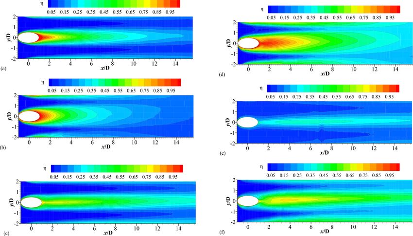
K. Zheng et al. Experimental Thermal and Fluid Science 127 (2021) 110410
Nomenclature po2 Partial pressure of oxygen
s Spanwise pitch between the adjacent holes
Co2 Mass concentration of oxygen molecules w Width of the vortex generator
D Film cooling hole diameter β Injection angle of the cooling hole
Ec Eckert number of the main flow η Film cooling effectiveness
I Momentum flux ratio of coolant flow to mainstream δ Boundary layer thickness
L Distance between the trailing edge of the VG and the center δ1 Displacement thickness of the boundary layer
of downstream film cooling hole λci Swirling strength of the vortex
Le Lewis number, Le = α/Ds , where α is the thermal
diffusivity and Ds is the mass diffusion coefficient Subscript
M Blowing ratio,ρC UC /ρ∞ U∞ ave, span Spanwise averaged
MW Molecular weight ratio of the coolant gas to the ∞ Inlet condition
mainstream gas c Coolant flow condition
ReD Reynolds number based on the diameter of the film cooling aw Adiabatic wall
hole Acronyms
Tu Turbulence intensity of the main flow anti-CRVP Anti-counter-rotating vortex pair
U Mainstream velocity CRVP Counter-rotating vortex pair
h Height of the vortex generator VG Vortex generator
l Entry length of the cooling hole
lVG Length of the vortex generator
generated inside the hole before ejection are considered in this strategy. found that the strong downwash effect of the vortex system generated by
For example, Vogel [17] demonstrated that a left-curved inflow gener the VG significantly reduced the lift-off tendency of the jet flow, thereby
ated a vortex system inside the hole that counter-rotated against the improving the film cooling performance.
external CRVP. This additional vortex system significantly reduces the The above studies indicate that the VG geometry can enhance the
strength of the CRVP and prevents the detachment of the jet flow from film cooling effectiveness. However, most previous studies placed the
the surface. Furthermore, using two or more holes is also an effective VG downstream of the film cooling holes, thus the VG should be high
method to improve film cooling performance. Kuster et al. [18] intro enough to ensure that it can interact with the jet flow under high
duced a double-jet film cooling (DJFC) concept to establish an anti- blowing ratios. In fact, the VG heights generally exceeded 0.75D (D is the
CRVP through two neighboring cooling holes with compound angles. diameter of the cooling hole) in the previous studies, which leads to a
Subsequently, a Nekomimi cooling hole [19] was proposed to achieve high pressure loss. If the VG was placed in front of the cooling hole and
the appropriate supply of cooling gas based on the DJFC concept. faced the high-speed incoming flow, the resulting vortex pairs should be
Heidmann and Ekkad [20] proposed an “anti-vortex” film cooling stronger than that generated by VG placed in the low-speed wake region
concept, in which two branched holes are drilled on both sides of the downstream of the jet flow. In addition, the approaching hot gas in the
main hole. The vortices generated by the two branched holes effectively main flow might be deflected away from the surface if the VG was placed
counteract the detrimental CRVP ejected from the main hole. In addi upstream of the cooling hole. Based on these assumptions, a VG with
tion, a novel sister hole structure was numerically investigated by Ely lower height (h = 0.25D and 0.5D) is placed upstream of the film cooling
and Jubran [21–22]. In this concept, the two sister holes were placed hole to investigate if the VG height can be decreased without losing the
slightly downstream of the main cooling hole. The results indicated that film cooling efficiency. The experimental study is conducted in a low-
the CRVP ejected from the main hole was impaired substantially by the speed wind tunnel located at Shanghai Jiao Tong University. A
two sister holes, leading to a significant improvement of film cooling pressure-sensitive paint (PSP) technique based on the analogy of heat
performance. and mass transfer [30–31] is utilized to measure the distribution of the
In addition to the above cooling hole designs, strategies related to adiabatic film cooling effectiveness on the test surface. The flow features
surface restructuring around the cooling hole were proposed in recent are comprehensively measured using two-dimensional particle image
years to improve the film cooling performance. Lu et al. [23] proposed velocimetry (2D-PIV) and stereoscope particle image velocimetry
placing a row of film cooling holes into a surface trench to modify the (SPIV). The measured flow field characteristics are correlated with the
interaction between the boundary layer and the jet flow. Na and Shih PSP measurements to elucidate the effects of the upstream VG structure
[24] placed a two-dimensional ramp with a backward-facing step in on the film cooling performance.
front of the coolant hole. The simulation results showed that the
approaching boundary layer flow was deflected away from the surface, 2. Experimental setup
and the interaction of the boundary layer flow and coolant jet occurred
far away from the surface. The laterally averaged film cooling effec 2.1. Experimental apparatus and test model
tiveness was improved at least two-fold by the ramp. More recently, a
three-dimensional vortex generator (VG) that generates opposite vortex The experimental investigation was conducted in a low-speed wind
pairs to eliminate the negative effects of the CRVP was proposed by tunnel located at the School of Aeronautics and Astronautics in Shanghai
Rigby and Heidmann [25]. Subsequently, Zaman et al. [26–27] placed a Jiao Tong University. The wind tunnel has an optically-transparent test
VG downstream of the inclined jet flow and experimentally demon section with a cross-section of 250 mm × 125 mm. The maximum flow
strated the effectiveness of a downstream VG for preventing lift-off of a velocity in the test section can reach 40 m/s. A honeycomb and screen
jet flow. Similar results were obtained by Shinn and Vanka [28] in a structure installed upstream of the contraction section ensure a uniform
large eddy simulation (LES). Furthermore, Song et al. [29] experimen low-turbulence incoming flow in the test section. The turbulence level of
tally investigated the effects of the inclination angle (20◦ , 30◦ , and 40◦ ) the incoming flow was within 0.5%. The mainstream velocity in all test
and blowing ratio (M = 0.5, 1.0, and 1.5) on the film cooling perfor cases was U∞ = 20m/s. As indicated by Baldauf and Scheurlen [32], the
mance when a VG was placed downstream of the cooling hole. It was Reynolds number based on the diameter of film cooling hole (ReD ) for
2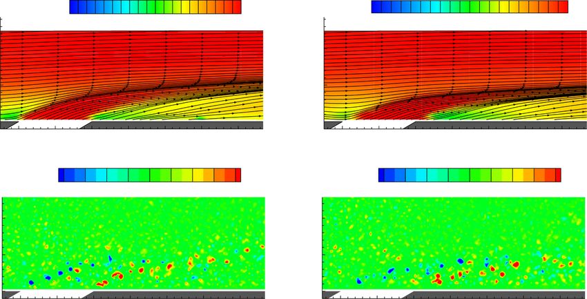
K. Zheng et al. Experimental Thermal and Fluid Science 127 (2021) 110410
real gas turbine engine applications is approximately ranging from 104
to 105 . Anderson et al. [33] indicated that the ReD is within a range of
(0.5 4) × 104 for a gas turbine operating under real condition. In the
present study, the Reynolds number based on the diameter of the film
cooling hole was ReD = 1.6 × 10⁴ , which is in the range of the typical
Reynolds number to investigate the film cooling of gas engine turbine
blades. The boundary layer profiles measured just upstream of the
cooling holes for the baseline case (i.e., without a VG placed on the test
plate) is shown in Fig. 1. It is observed that the boundary layer profile is
in good agreement with the 1/7th power law, indicating that the
incoming flow is a fully-developed turbulent flow. The turbulent
boundary layer thickness was estimated based on the velocity profile
shown in Fig. 1; it was approximately 1.52D.
The test model of the film cooling holes with the upstream VGs is
shown in Fig. 2. A row of 5 discrete circular holes with the same di
ameters of D = 6.0mm was designed to inject coolant gas over a flat plate
with an injection angle of β = 30 . The entry length of the cooling holes
◦
was l = 5D. The spanwise pitch between the adjacent holes was set to be
s = 3D, which is identical to the typical spacing between coolant holes
in the spanwise direction for real gas turbine engine [2]. The VGs were
placed upstream of each film cooling hole, and the axial centerline of the
VGs coincided with those of the cooling holes. The length and width of
the VG were fixed at lVG = 2D and w = 1.5D, respectively. As described
Fig. 2. The schematic of the film cooling configuration with the VG.
in the introduction, two VG heights (h = 0.25D and 0.5D) were tested in
the experiments. In addition, the distance between the trailing edge of
temperature of the test surface, and Tc is the temperature of the coolant
the VG and the center of the cooling hole was defined as L. Two distances
stream. The primary challenge in obtaining adiabatic film cooling
(L = D and 2D) were investigated to evaluate the effects of the VG
effectiveness is the measurement of adiabatic wall temperature because
location on the film cooling effectiveness. As shown in Fig. 2, for the
the heat conduction in a test model cannot be entirely avoided during
distance of L = D, the trailing edge of the VG contacts the leading edge
the experiments.
of the cooling hole. Three blowing ratios (M = ρC UC /ρ∞ U∞ = 0.2, 0.4,
In the present study, instead of measuring adiabatic wall tempera
0.8, where ρC and UC are the density and velocity of the coolant flow,
ture, a PSP technique operating under isothermal condition was used to
and ρ∞ is the density of the main flow) were adopted to investigate the
measure the film cooling effectiveness based on the analogy of heat and
effects of the blowing ratio on the performances of the upstream VGs.
mass transfer [34–35]. Johnson et al. [36] indicated that the PSP based
cooling effectiveness measurements can avoid the problems related to
2.2. PSP technique to measure the film cooling effectiveness the effects of heat conduction in the test model on the measurement of
the adiabatic wall temperature. In addition, as described by Shadid and
Adiabatic film cooling effectiveness η is generally defined as: Eckert [34], the differential equations regarding heat and mass transfer
can be treated as analogous if the Lewis number (Le = α/Ds , where α is
T∞ − Taw
η = (1) the thermal diffusivity and Ds is the mass diffusion coefficient) was
T∞ − Tc
approximately 1.0, which is the case of the present study.
where T∞ is the temperature of the main flow, Taw is the adiabatic wall For the PSP measurements, the plate surface is coated with a layer of
oxygen-sensitive paint, consisting of luminophore molecules and a gas-
permeable polymeric binder. When excited by ultraviolet (UV) light, the
luminophore molecules emit photoluminescence with a longer wave
length when returning to the ground state from the excited state.
However, the emission of luminophore molecules can be inhibited due
to the existence of surrounding oxygen molecules. This phenomenon is
called oxygen quenching, where the intensity of the photoluminescence
is inversely proportional to the concentration of the local oxygen.
Consequently, the concentration of oxygen molecules can be calculated
based on the recorded light intensity and a calibration procedure.
For the PSP based cooling effectiveness measurements, air flow is
typically used to simulate the mainstream, while oxygen-free gas (e.g.,
nitrogen or carbon dioxide) is supplied as the coolant stream. The
oxygen-free gas ejected through the coolant holes prevents the oxygen
molecules in mainstream (i.e., air flow) from reaching the surface of
interest. The film cooling effectiveness is determined in terms of the
oxygen concentration over the protected surface. Thus, by replacing the
temperature in Eq. (1) with the oxygen concentration, the film cooling
effectiveness can be expressed as:
CO2 ,main − CO2 ,mix CO ,main − CO2 ,mix
η = = 2 (2)
CO2 ,main − CO2 ,coolant CO2 ,main
As indicated by Charbonnier et al. [37], by choosing an oxygen-free
Fig. 1. Measured boundary layer profile of the mainstream over the test plate. coolant gas whose molecular mass differs distinctly from that of the
3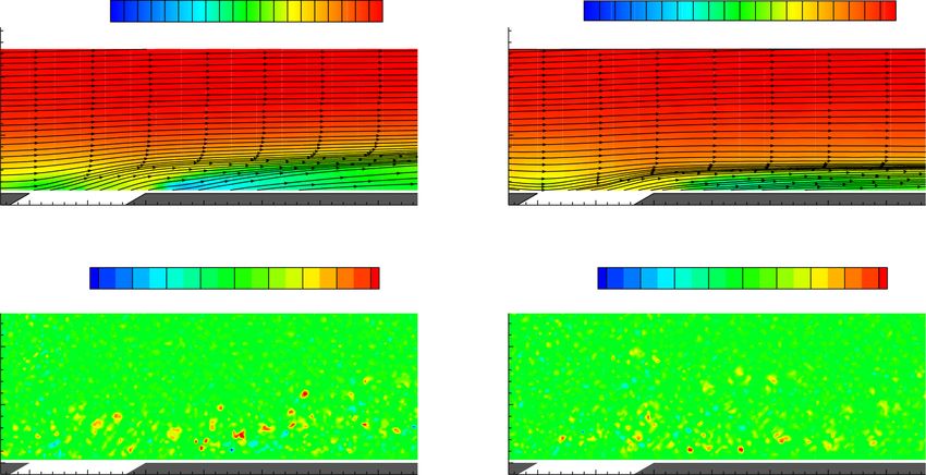
K. Zheng et al. Experimental Thermal and Fluid Science 127 (2021) 110410
mainstream, the film cooling effectiveness based on the measurement of
the partial pressure of oxygen should be calculated as:
1
η = 1 - [( ) ( ) ] (3)
po 2 air
/ po2 mix − 1 MW + 1
where MW is the molecular weight ratio of the coolant gas to the
mainstream gas. (po2 )air and (po2 )mix are the partial pressures of oxygen
measured in the air and on the film cooling surface, respectively.
The pressure terms in Eq. (3) can be determined by using the
recorded intensity of the emitted light, which is a function of the partial
pressure of oxygen (i.e., local oxygen concentration). The function
describing the relationship between the normalized intensity and partial
pressure can be determined by a PSP calibration procedure. More in
formation on the details of the PSP technique, such as image processing,
and calibration process can be found in [38].
Fig. 3 shows the experimental setup for the PSP measurements. A
constant UV light with a wavelength of 405 nm was used as the exci
tation light source for the PSP measurements. A 14-bit charge-coupled Fig. 4. Uncertainty of measured film cooling effectiveness along the centerline
device (CCD) camera (PCO2000, Cooke Corp.) with a 610 nmlong- of the coolant hole (baseline case, M = 0.4).
pass filter was used to record the photoluminescence light emitted by the
luminophore molecules in the PSP paint. The PSP used in this study was uncertainty varies from 3% to 9% with the increase of distance down
Unicoat (ISSI), which has a low sensitivity to temperature change stream the coolant hole.
( 1.3%/ C). The coolant flow temperature was kept equal to that of the
◦
main flow to reduce the influence of temperature, and the temperature
fluctuation during the measurements was less than 0.5 C.
◦ 2.3. Flow field measurements using 2D-PIV and SPIV
In the present study, an interrogation window of 9 × 9 pixels with
50% overlap was used in image processing to minimize the effects of In this study, the flow field measurements were conducted using 2D-
random noise in the images. The acquired images had a magnification of PIV and SPIV to quantify the mixing process of the coolant and the
0.07 mm/pixel, resulting in a spatial resolution of 0.32 mm for the PSP mainstream flow downstream of the film cooling holes. During the PIV
measurements. As indicated by Johnson and Hu [36], the PSP based measurements, the incoming airflow and the coolant flow (i.e., N2 in this
cooling effectiveness measurement has a varying degree of uncertainty, study) were both seeded with oil droplets (diameter of approximately
which directly depends on the local behavior of the mixing process be 1μm) generated by seeding generators. The measured plane was illu
tween the mainstream and coolant flows. The measured film cooling minated by a double-pulsed Nd:YAG laser (Vlite-380, Beamtech) with a
effectiveness with error bar along the centerline of coolant hole for the pulse energy of 380mJ at 10 Hz repetition rate. The thickness of the laser
baseline case (without upstream VG) is plotted in Fig. 4. The absolute sheet shaped by a set of spherical and cylindrical lenses was approxi
uncertainty was found to increase continuously with the decrease of film mately 1.0 mm in the measurement region. The image acquisition de
cooling effectiveness, which is approximately 0.018 for η = 0.7 in the vices used in the PIV measurements were 14-bit CCD cameras
region near the coolant hole and is 0.028 for η = 0.3 in the far field (PCO2000, Cooke Corp.) with a resolution of 2048 × 2048 pixels. The
region away from the coolant hole. The corresponding relative cameras and double-pulsed Nd:YAG laser were connected to a digital
delay generator (Berkeley Nucleonics 575), which controlled the timing
Fig. 3. Experimental setup for the PSP measurements.
4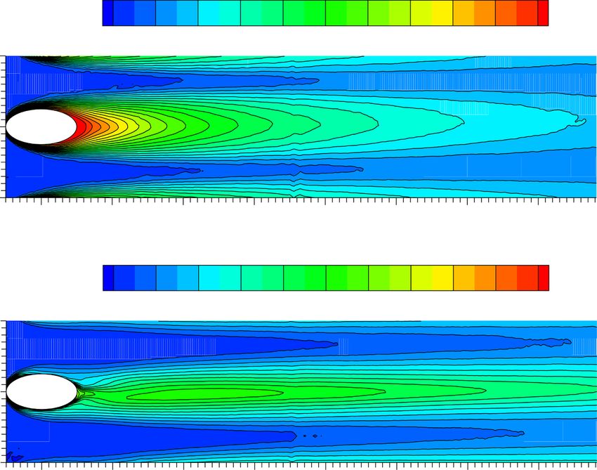
K. Zheng et al. Experimental Thermal and Fluid Science 127 (2021) 110410
of the laser illumination and image acquisitions. observed in the spanwise direction in Fig. 6(b). The cooling film be
The diagram of the measurement setup is shown in Fig. 5. PIV comes thinner as the coolant gas expands in the spanwise direction. If
measurements were conducted to measure velocity components from the cooling film is too thin, its ability to resist the influx of the main flow
two orthogonal views: vertical streamwise (x − z) plane and vertical on the surface is weakened. Since the cooling film is very thin at a low
spanwise (y − z) plane. As shown in Fig. 5, while 2D-PIV was performed blowing ratio (e.g., M = 0.2), a further reduction in the film thickness
in x − z plane passing through the centerline of the middle film cooling caused by the presence of the VG deteriorates the film cooling perfor
hole on the test plate (i.e.,y = 0), SPIV was conducted in two y − z planes mance as the coolant flow moving downstream. Therefore, as shown in
(i.e., x/D = 3 and 6 downstream the center of film cooling hole). Fig. 6(a) and (b), the film cooling effectiveness decreases slightly faster
A grid target placed in the laser sheet is used to calibrate the 2D-PIV than that of the baseline case in the streamwise direction.
measurement, which provides a scale factor by converting the length At a blowing ratio of M = 0.4, the cooling film is relatively thick;
scale from the measurement plane to the image plane. S-PIV calibration therefore, the expansion of the coolant gas in the spanwise direction has
was performed by following a general in-situ multi-plane procedure no adverse effect on the film cooling performance in the streamwise
described by Raffel et al. [39]. After PIV image acquisition, the instan direction. In addition, the film cooling effectiveness near the hole exit is
taneous PIV velocity vectors were obtained by a frame-to-frame cross- higher than that of the baseline case, indicating that the coolant jet is
correlation technique with an interrogation window of 24 × 24 pixels. still attached to the surface at this blowing ratio. Thus, the cooling gas is
An effective overlap of 50% of the interrogation windows was utilized in utilized more efficiently due to the presence of the VG. It can be
the PIV image processing. Consequently, the spatial resolution for 2D- observed in Fig. 6(c) and (d) that the coverage of the coolant gas is
PIV and SPIV measurements were 0.26 mm and 0.31 mm, respec highly improved by the upstream VG in both the spanwise and
tively. After the instantaneous velocity vectors were determined, the streamwise directions.
ensemble-averaged flow quantities, such as the mean velocity (u, v, w) The most significant improvements in the film cooling effectiveness
and the spanwise vorticity (ωy) for the 2D-PIV measurements and the caused by the upstream VG occur at a high blowing ratio (e.g., M = 0.8).
streamwise vorticity (ωx) for the SPIV measurements were obtained The separation of the coolant jet from the plate surface is significantly
from a sequence of 900 frames of the instantaneous PIV measurements. inhibited by the upstream VG. The region with relatively high film
The uncertainty level for the PIV measurements was within 3% for the cooling effectiveness is much larger in the spanwise and streamwise
instantaneous velocity vectors and that of the ensemble-averaged flow directions compared with the narrow and short coverage area of the
quantities, such as the vorticity distributions, was approximately 10%. coolant gas in the baseline case. The results in Fig. 6 suggest that the VG
installed upstream of the cooling hole significantly improves the film
3. Results and discussion cooling effectiveness, and this effect is more pronounced at relatively
high blowing ratios (e.g., M = 0.4, 0.8). In addition, the coverage range
3.1. Effects of the VG on the film cooling effectiveness of coolant gas in spanwise direction was found to be dominated by the
upstream VG structure. Therefore, the VG geometry can be used to
The distribution of film cooling effectiveness on the test plate with control the expansion of the coolant gas within a wide range of the
the VG mounted upstream of the cooling hole is shown in Fig. 6. The blowing ratio.
baseline cases without the upstream VG are also plotted for comparison. The comparisons of the centerline and spanwise-averaged film
For the baseline cases, the film cooling effectiveness increases with an cooling effectiveness between the VG and the baseline cases are plotted
increase in the blowing ratio from 0.2 to 0.4. However, it should be in Fig. 7 to quantify the effects of the upstream VG on the film cooling
noted that in the region near the hole exit, the film cooling effectiveness performance. At a relatively low blowing ratio (e.g., M = 0.2), with the
at M = 0.4 is lower than that at M = 0.2, indicating that the coolant jet continuous mixing of the coolant gas with the main flow downstream of
has slightly separated from the surface. With a further increase in the the coolant hole, the magnitudes of both the centerline and spanwise-
blowing ratio, the decrease in the film cooling effectiveness caused by averaged film cooling effectiveness decrease gradually with an
the separation of the coolant streams exceeds the benefits of increasing increasing downstream distance. The VG presence results in a decrease
the cooling gas flux. It can be seen in Fig. 6(e) that the film cooling in the centerline film cooling effectiveness of 7–20% compared with the
performance deteriorates rapidly as the blowing ratio increases to M = baseline case. However, the spanwise-averaged film cooling effective
0.8. ness is improved by 11–43% due to the presence of upstream VG. This
After installing the VG in front of the cooling hole, the coverage area finding indicates that the spreading of the coolant gas in the spanwise
of the coolant gas is larger than that in the baseline case, resulting in a direction is wider and more uniform in the VG case, which agrees with
better film cooling performance at all three blowing ratios, as shown in the distributions shown in Fig. 6(a).
Fig. 6. For M = 0.2, a higher surface coverage of the coolant gas is At a blowing ratio of M = 0.4, both the centerline and spanwise-
Fig. 5. Experimental setup for the 2D-PIV and SPIV measurements.
5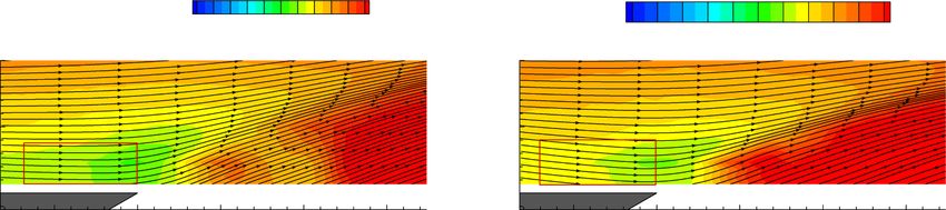
K. Zheng et al. Experimental Thermal and Fluid Science 127 (2021) 110410
Fig. 6. Comparison of the film cooling effectiveness between the baseline and the VG cases (a) M = 0.2, baseline; (b) M = 0.2, VG; (c) M = 0.4, baseline; (d) M = 0.4,
VG; (e) M = 0.8, baseline; (f) M = 0.8, VG.
Fig. 7. Comparison of the (a) centerline and (b) spanwise-averaged film cooling effectiveness between the VG and the baseline cases.
averaged film cooling effectiveness values are higher than those of the followed by an increase in the centerline film cooling effectiveness (i.e.,
baseline case. The difference in the centerline film cooling effectiveness x/D < 3.0) is much shorter than that of the baseline case. These results
between the cases is especially large in the region of x/D < 6 because the indicate that the separation of the coolant flow from the surface has been
separation of the coolant flow in the baseline case is eliminated after the substantially suppressed by the upstream VG.
VG installation. In addition, the VG has a more substantial effect on the
spanwise-averaged film cooling effectiveness than the centerline film
3.2. Effects of the VG on the flow structure downstream of the film cooling
cooling effectiveness, i.e., a 40–113% increase in effectiveness
hole
compared with the baseline case.
At the blowing ratio of M = 0.8, the centerline film cooling effec
3.2.1. Flow characteristics in the streamwise plane measured by 2D-PIV
tiveness of the baseline case decreases rapidly near the hole exit (i.e., x/
High-resolution PIV measurements were conducted to determine the
D < 2) and then gradually increases in the region of 2 < x/D < 5. With a
detailed flow field, investigate the mixing process between the coolant
further increase in the downstream distance, the film cooling effec
jet and the main flow, and explore the underlying mechanism respon
tiveness decreases gradually due to the continuous mixing of the coolant
sible for the improvements in the film cooling performance by placing
gas with the main flow. Both the centerline and spanwise-averaged film
the VG upstream of the cooling hole. The flow field measurements in the
cooling effectiveness values increase significantly after installing the VG
streamwise plane (i.e., z = 0) for the baseline and the VG cases at
in front of the film cooling hole. As shown in Fig. 7(a), the decline in the
blowing ratios of M = 0.2, 0.4, and 0.8 are shown in Figs. 8–10. At a
centerline film cooling effectiveness near the hole exit is not as large as
relatively low blowing ratio of M = 0.2, the cooling streams injecting
that of the baseline case. In addition, the distance of the initial decrease
through the inclined hole remain attached to the test surface in both the
6
K. Zheng et al. Experimental Thermal and Fluid Science 127 (2021) 110410
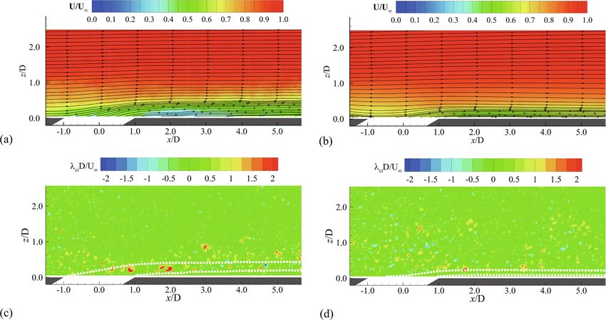
Fig. 8. Flow field measured in the streamwise plane for the baseline and the VG cases at the blowing ratio of M = 0.2. (a) Ensemble-averaged velocity, baseline case;
(b) Ensemble-averaged velocity, VG case; (c) Instantaneous swirling strength, baseline case; (d) Instantaneous swirling strength, VG case.
Fig. 9. Flow field measured in the streamwise plane for the baseline and the VG cases at the blowing ratio of M = 0.4. (a) Ensemble-averaged velocity, baseline case;
(b) Ensemble-averaged velocity, VG case; (c) Instantaneous swirling strength, baseline case; (d) Instantaneous swirling strength, VG case.
baseline and the VG cases. As shown in Fig. 8(b), the thickness of the film cooling effectiveness in the region of x/D < 3.8.
cooling film is reduced by the presence of the upstream VG structure. With a further increase in the blowing ratio, the coolant gas rapidly
The thin layer of coolant gas cannot prevent the influx of the main flow moves away from the surface after being ejected from the cooling hole.
on the surface. As a result, the centerline film cooling effectiveness is not The streamlines in Fig. 10(a) reveal that most of the coolant gas has
improved by the VG at the blowing ratio of M = 0.2, as shown in Fig. 7 penetrated into the mainstream flow, resulting in a very low film cooling
(a). performance on the test surface. As shown in Fig. 10(b), although the
At the blowing ratio of M = 0.4, the detachment of the coolant jet separation of the coolant gas is observed in the VG case, the downward
from the surface can be observed near the hole exit for the baseline case, deflection of the coolant flow streamlines is more apparent than in the
resulting in a lower centerline film cooling effectiveness than for M = baseline case due to the downwash flow induced by the upstream VG.
0.2. After installing the VG upstream of the cooling hole, the downwash The cooling stream is closer to the surface than in the baseline case. This
flow induced by the VG prevents the coolant gas from lifting off the change in the coolant flow highly improves the film cooling efficiency
surface. It can be seen in Fig. 9(b) that the separation of the coolant jet over the surface, as shown in Fig. 6(f) and 7.
from the surface has disappeared, leading to an increase in the centerline In the film cooling flow fields, the shearing motions in the boundary
7
K. Zheng et al. Experimental Thermal and Fluid Science 127 (2021) 110410
Fig. 10. Flow field measured in the streamwise plane for the baseline and the VG cases at the blowing ratio of M = 0.8. (a) Ensemble-averaged velocity, baseline
case; (b) Ensemble-averaged velocity, VG case; (c) Instantaneous swirling strength, baseline case; (d) Instantaneous swirling strength, VG case.
layer flow are the dominant contributors to vorticity. In the vorticity is opposite to that at the low blowing ratio. It is observed that the
plots, it nearly impossible to distinguish the swirling motions of the rotation direction of the Kelvin-Helmholtz vortices on the windward
vortex structures from the strong shearing motions. In this study, we use side changes from clockwise to counter-clockwise as the blowing ratio
the swirling strength to visualize the vortex structures in the film cooling increases from M = 0.4 to M = 0.8.
flow fields. Chong et al. [40] described the swirling strength as the
imaginary part of the complex eigenvalue of the velocity gradient 3.2.2. Flow characteristics in the cross-plane measured by SPIV
tensor; it can be used to distinguish between swirling motions and shear As shown in Figs. 9 and 10, the coolant jet lifts off the surface and
motions. As shown in Figs. 8 to 10, the instantaneous swirling strength penetrates the mainstream at high blowing ratios, leading to a decrease
reveals the mixing process of the coolant gas with the main flow. Un in the film cooling effectiveness. As mentioned in the introduction, the
steady vortex structures caused by Kelvin-Helmholtz instabilities are CRVP in the streamwise direction is believed to be responsible for the
formed surrounding the coolant jet and shed periodically in the shear poor film cooling performance at high blowing ratios. Thus, the
layer between the coolant flow and the main flow. streamwise vortices are vital for film cooling performance. In this study,
At a relatively low blowing ratio of M = 0.2, the shear layer between a SPIV system was used to measure the flow fields in the cross-plane (i.e.,
the cooling stream and the mainstream is only formed at the windward the y-z plane) to reveal the generation and evolution of the streamwise
side because the coolant flow is attached to the test plate, resulting in the vortex structures in the baseline and VG cases.
formation of Kelvin-Helmholtz vortices in this shear layer region. The Fig. 11 shows the measurement results of the SPIV at x/D = 3 for the
streamlines originated from the leading and trailing edge of the film baseline and the VG cases at different blowing ratios. At a low blowing
cooling hole were also plotted in Fig. 8(c) and (d). It can be seen that ratio (i.e., M = 0.2), the CRVP generated by the coolant jet is close to the
after mounting the VG upstream of the cooling hole, the coolant jet surface and has a very low intensity. This behavior of the CRVP agrees
moves closer to the surface and the shear layer thickness is highly with the streamline characteristics plotted in Fig. 8(a), indicating that
reduced. In addition, both the strength and the quantity of Kelvin- the coolant jet remains attached to the surface after blowing out of the
Helmholtz vortices in the shear layer are reduced compared to the cooling hole. At relatively high blowing ratios (i.e., M = 0.4, 0.8), the
baseline case. CRVP is observed clearly in the plot of the swirling strength distribution
At the blowing ratio of M = 0.4, the Kelvin-Helmholtz vortices on the in Fig. 11(c) and 11(e). It can be seen that the strength of the CRVP in the
lee side begin to appear in the baseline case due to the detachment of the coolant jet is greatly enhanced with the increase of blowing ratio.
cooling stream from the tested surface; this phenomenon is observed in Meanwhile, the CRVP was found to rapidly rise away from the surface at
the region near x/D = 3, as shown in Fig. 9(c). After installing the VG, high blowing ratios due to the separation of coolant jet after being
the flow separation is suppressed, and the coolant gas remains attached ejected from the cooling hole.
to the surface. Therefore, the Kelvin-Helmholtz vortices are not After installing the VG upstream of the cooling hole, apart from the
observed on the lee side of the cooling stream in the VG case, as shown in CRVP generated in the coolant injection, an additional CRVP induced by
Fig. 9(d). the upstream VG is also observed. The rotation direction of the addi
At the blowing ratio of M = 0.8, the Kelvin-Helmholtz vortices on the tional CRVP is opposite to that of the CRVP induced by the coolant in
lee side are observed in the baseline and VG cases due to the separation jection; therefore, this additional vortex pair is referred to as the anti-
of the cooling stream from the tested surface. As the coolant flow moves CRVP. This vortex structure downstream of the triangular ramp-
downstream, the strength of the Kelvin-Helmholtz vortices decreases shaped structure was also reported by Zaman et al. [26–27] and Shinn
gradually due to the continuous mixing of the coolant gas with the main and Vanka [28].
flow. The vortices on the windward side are maintained for a longer Due to the rotation direction of the anti-CRVP, a downwash flow
distance in the VG case than the baseline case, indicating that the up occurs between the two vortices of the anti-CRVP, pushing the coolant
stream VG delays the mixing process of the coolant gas with the main jet closer to the surface and improving the film cooling performance.
flow, thereby increasing the film cooling efficiency. In addition, since Besides, the existence of the anti-CRVP causes the coolant flow near the
the velocity of the coolant flow is higher than the surrounding main surface to move outward, promoting the spread of the coolant gas in the
stream velocity, the rotation direction of the Kelvin-Helmholtz vortices spanwise direction and resulting in better lateral coverage of the cooling
8K. Zheng et al. Experimental Thermal and Fluid Science 127 (2021) 110410
Fig. 11. Flow field in the cross-plane at x/D = 3 for the baseline cases and the VG cases at different blowing ratios. (a) M = 0.2, baseline case; (b) M = 0.2, VG case;
(c) M = 0.4, baseline case; (d) M = 0.4, VG case; (e) M = 0.8, baseline case; (f) M = 0.8, VG case.
film compared with that of the baseline case. Therefore, it can be seen in downstream distance increases, the strength of the CRVP decreases due
Figs. 6 and 7(b) that the spanwise-averaged film cooling effectiveness is to turbulent mixing between the coolant gas and the main flow. After
improved by the existence of the VG. installing the VG in front of the hole, the anti-CRVP induced by the VG
At a low blowing ratio (i.e., M = 0.2), the anti-CRVP dominates the pushes the lifted CRVP back to the surface and weakens the strength of
flow structures in the cross-plane for the VG case since the CRVP induced the CRVP. These interactions of the anti-CRVP and the CRVP suspend
by the coolant injection is weak. In contrast, faster spanwise spreading of the detachment of the coolant jet from the surface, significantly
the coolant gas is induced by the anti-CRVP, and the thickness of the enhancing the film cooling effectiveness.
cooling film near the centerline of the hole is decreased, resulting in a
lower centerline film cooling effectiveness compared with that of the 3.3. Effect of the VG height on the film cooling performance
baseline case. At relatively high blowing ratios (i.e., M = 0.4, 0.8), the
lifted CRVP is pushed back to the surface by the anti-CRVP, and the As described above, the film cooling effectiveness can be improved
strength of the CRVP has decreased due to vorticity cancellation effect. by the VG due to the generation of the anti-CRVP. It is expected that the
In addition, the strength of the anti-CRVP decreases gradually with an increase of VG height enhances the strength of the anti-CRVP. However,
increase in the blowing ratio as a result of a continuous enhancement of the incursion of the VG into the main flow also becomes stronger,
the vorticity cancellation effect between the CRVP and the anti-CRVP. resulting in additional pressure loss. Thus, it is necessary to examine the
Besides the vortex strength, the position of the vortices in the anti- effects of the VG height on the film cooling performance. It should be
CRVP also differs for different blowing ratios. As the blowing ratio in noted that the measurement results in Sections 3.1 and 3.2 were ob
creases, the anti-CRVP gradually moves closer to the surface, and the tained using the VG with a height of h = 0.5D. This height is lower than
spacing between the two vortices in the anti-CRVP increases due to an that in previous studies where the VG was placed downstream of the
increase in the strength of the CRVP generated by the coolant injection. cooling hole. Since the main purpose of this study is to investigate the
The streamwise vortex structures measured at two typical stream possibility of decreasing the VG height, the film cooling effectiveness
wise locations (i.e., x/D = 3 and 6) for the baseline and VG cases at a and flow field characteristics for the case with a VG height of h = 0.25D
blowing ratio of M = 0.8 are shown in Fig. 12. It is observed that the flow was measured in this study. Fig. 13 shows the distribution of the film
structures downstream of the cooling hole are dominated by a large- cooling effectiveness for the case with a VG height of h = 0.25D. As
scale streamwise vortex pair (i.e., CRVP) in the baseline case. As the shown in Figs. 6 and 13, the film cooling performance decreases with a
9K. Zheng et al. Experimental Thermal and Fluid Science 127 (2021) 110410
The spanwise-averaged film cooling effectiveness is even higher than
that of the case with VG height of h = 0.5D in the far downstream region
(i.e., x/D > 11). At a high blowing ratio (i.e., M = 0.8), both the
centerline and spanwise-averaged film cooling effectiveness decrease
with a reduction in the VG height. In addition, the spanwise-averaged
film cooling effectiveness is more sensitive than the centerline cooling
effectiveness to the VG height, as shown in Fig. 14.
Fig. 15 shows the streamwise velocity distribution between the
trailing edge of the VG and the center of the cooling hole at a blowing
ratio of M = 0.8. The flow downwash can be observed near the leading
edge of the cooling hole for the VG height of h/D = 0.5. However, this
flow downwash phenomenon is less pronounced for the VG height of h/
D = 0.25, as shown in Fig. 15(a). Therefore, the detachment of the
coolant flow from the surface is not substantially hindered by the
downwash flow, leading to a relatively lower centerline film cooling
effectiveness at a lower VG height.
3.4. Effects of the streamwise distance between the VG and cooling hole
on the film cooling performance
In addition to the VG height, the distance between the VG and the
cooling hole is also investigated in this study. The previous results were
obtained for VG locations of L = 2D. An additional VG location with a
shorter distance upstream of the cooling hole (i.e., L = D) is selected to
Fig. 12. Evolution of the streamwise vortex structures for (a) the baseline case evaluate the effects of the VG location on the film cooling effectiveness.
and (b) the VG case at the blowing ratio of M = 0.8. Fig. 16 compares the centerline and spanwise-averaged film cooling
effectiveness between the two different VG streamwise locations. At a
decrease in the VG height because the flow downwash and the anti- low blowing ratio (M = 0.2), the centerline film cooling effectiveness
CRVP are weaker at a lower VG height. However, compared with the with a VG location of L = 2D is close to that of the baseline case. In
baseline case, the film cooling performance is also significantly contrast, the spanwise-averaged film cooling effectiveness shows an
improved by the VG with a lower height of h = 0.25D at different improvement over the baseline case, and the values are even higher than
blowing ratios. those of the case with a VG location of L = D in the downstream region of
Fig. 14 shows the centerline and spanwise-averaged film cooling x/D > 7. As the blowing ratio increases to M = 0.8, it is observed in
effectiveness extracted from Figs. 6 and 13. At a relatively low blowing Fig. 16(c) and (d) that both the centerline and spanwise-averaged film
ratio (i.e., M = 0.2), the centerline film cooling effectiveness is slightly cooling effectiveness values decrease with an increase in the upstream
lower, and the spanwise-averaged film cooling effectiveness is sub distance L. However, the VG location has a smaller influence on the film
stantially higher than the baseline case for the VG height of h = 0.25D. cooling effectiveness than the VG height. As shown in Fig. 16(a) and (b),
a longer upstream distance of VG is beneficial at a low blowing ratio.
Fig. 13. Film cooling effectiveness for the cases with a VG height of h = 0.25D at blowing ratios of (a) M = 0.2 and (b) M = 0.8.
10K. Zheng et al. Experimental Thermal and Fluid Science 127 (2021) 110410
Fig. 14. Film cooling effectiveness for different VG heights; (a) centerline film cooling effectiveness, M = 0.2; (b) spanwise-averaged film cooling effectiveness, M =
0.2; (c) centerline film cooling effectiveness, M = 0.8; (d) spanwise-averaged film cooling effectiveness, M = 0.8.
Fig. 15. Flow fields measured in the streamwise plane with different VG heights at M = 0.8 (a) h = 0.25D; (b) h = 0.5D.
Therefore, the streamwise location of the VG should be optimized parameters of VG, namely the height, width, length of the VG and the
carefully when the blowing ratio has a wide range. distance between the VG and the downstream film cooling hole, should
The dimensional analysis of film cooling problem was systemically be taken into consideration in the dimensional analysis.
conducted by Baldauf and Scheurlen [32]. They indicated that the
h, w, lVG , L (5)
dimensionless parameters of influence on the film cooling effectiveness
can be given as: Therefore, the dimensionless parameters for the film cooling effec
( ) tiveness can be shown as:
x y s l δ
η = f ReD , Ec, Tu, I, M, , , β, , , 1 (4) ( )
D D D D D x y s l δ h w l L
η = f ReD , Ec, Tu, I, M, , , β, , , 1 , , , VG , (6)
D D D D D D D D D
where Ec and Tu are the Eckert number and the turbulence intensity of
the main flow, respectively. I is the momentum flux ratio of mainstream In the present study, six dimensionless parameters (i.e., I,M,x/D,y/D,
to coolant flow, and δ1 is the displacement thickness of the boundary h/D, L/D) were varied to explore their influences on the film cooling
layer just upstream of the injection hole without coolant gas. performance over a VG structured film cooling surface. It can be found
The main difference between the present study and Baldauf and that the upstream VG structure can significantly enhance the film
Scheurlen [32] is the introduction of VG structure. Thus, the geometry cooling effectiveness at relatively high blowing ratio. This is mainly
11K. Zheng et al. Experimental Thermal and Fluid Science 127 (2021) 110410
Fig. 16. Film cooling effectiveness profiles for different VG locations; (a) centerline film cooling effectiveness, M = 0.2; (b) spanwise-averaged film cooling
effectiveness, M = 0.2; (c) centerline film cooling effectiveness, M = 0.8; (d) spanwise-averaged film cooling effectiveness, M = 0.8.
related to the anti-CRVP and downwash flow generated by the VG, investigated in this study. This effect was more pronounced at relatively
which retard the separation of coolant gas from the surface of interest. In high blowing ratios (M = 0.4 and 0.8). The cooling film coverage in the
addition, while the film cooling effectiveness can be significantly spanwise direction on the test surface was much more uniform than that
influenced by the VG height (h/D), the streamwise location of VG (L/D) of the baseline case. The spanwise-averaged film cooling effectiveness at
was found to has much less impact on the film cooling performance. the blowing ratio of M = 0.8 was 56–188% higher than that of the
As described above, the present study demonstrated that the pro baseline case.
posed upstream VG concept can be used to improve the film cooling The flow characteristics obtained from the PIV measurements indi
effectiveness. However, more extensive studies are still needed to cated that the dominant flow structure downstream of the cooling hole
elucidate the associated underlying physics and systemically examine consisted of two pairs of large-scale counter-rotating vortices. One was
the relevant dimensionless parameters shown in Eq. (6), in order to generated by the injection of the coolant jet and was referred to as the
explore/optimize design paradigms for better film cooling protection of CRVP. This CRVP in the coolant jet promotes the entrainment of the
turbine blades from harsh environments. coolant gas into the main flow and entrains the mainstream to the sur
face in the outer region of the jet, resulting in a decrease in the film
4. Conclusion cooling performance. Another CRVP, whose rotation direction was
opposite to that of the CRVP, was generated by the VG. This vortex pair
An experimental study was performed to evaluate the effects of an was referred to as the anti-CRVP, which pushed the lifted coolant jet
upstream micro VG on the film cooling performance as coolant gas was toward the surface, thereby improving the film cooling performance.
injected from downstream circular holes. A PSP technique based on the Meanwhile, the anti-CRVP increased the coverage area of the coolant
analogy of heat and mass transfer was used instead of the traditional gas due to its rotation direction, resulting in a more uniform distribution
temperature-based methods for measuring the film cooling effective of the film cooling effectiveness in the spanwise direction.
ness. In addition, a high-resolution PIV system was employed to explore
the evolution of the flow structures downstream of the cooling hole in CRediT authorship contribution statement
the streamwise plane and cross-plane. The relationship between the film
cooling effectiveness and the flow field measurements was determined Kuan Zheng: Formal analysis, Writing - original draft. Wei Tian:
to elucidate the underlying mechanisms responsible for the improve Conceptualization, Methodology, Formal analysis, Writing - review &
ments in the film cooling performance by the upstream micro VG editing, Funding acquisition, Supervision. Jiang Qin: Methodology,
structure. Formal analysis. Hui Hu: Conceptualization, Formal analysis, Writing -
The PSP measurement results revealed that the film cooling effec review & editing, Supervision.
tiveness on the test surface was improved significantly by the VG
mounted upstream of the cooling hole within the range of blowing ratios
12K. Zheng et al. Experimental Thermal and Fluid Science 127 (2021) 110410
Declaration of Competing Interest [19] K. Kusterer, A. Elyas, D. Bohn, T. Sugimoto, R. Tanaka, M. Kazari, The NEKOMIMI
cooling technology: cooling holes with ears for high-efficient film cooling, in: Proc.
ASME Turbo Expo, Paper No. GT2011-45524 (2011) 303-313.
The authors declare that they have no known competing financial [20] J.D. Heidmann, S. Ekkad, A novel antivortex turbine film-cooling hole concept,
interests or personal relationships that could have appeared to influence J. Turbomach. 130 (3) (2008), 031020.
the work reported in this paper. [21] M.J. Ely, B.A. Jubran, A numerical study on improving large angle film cooling
performance through the use of sister holes, Numer. Heat Tranf. A-Appl. 55 (7)
(2009) 634–653.
Acknowledgement [22] M.J. Ely, B.A. Jubran, A numerical evaluation on the effect of sister holes on film
cooling effectiveness and the surrounding flow field, Heat Mass Transf. 45 (11)
(2009) 1435–1446.
Funding support from National Natural Science Foundation of China [23] Y. Lu, A. Dhungel, S.V. Ekkad, R.S. Bunker, Effect of trench width and depth on
(No. 11872039) is gratefully acknowledged. film cooling from cylindrical holes embedded in trenches, J. Turbomach. 131 (1)
(2009), 011003.
[24] S. Na, T.I. Shih, Increasing adiabatic film-cooling effectiveness by using an
References upstream ramp, J. Heat Transf. 129 (4) (2007) 464–471.
[25] D.L. Rigby, J.D. Heidmann, Improved film cooling effectiveness by placing a vortex
[1] J.C. Han, S. Dutta, S. Ekkad, Gas Turbine Heat Transfer and Cooling Technology, generator downstream of each hole, in: Proc. ASME Turbo Expo, Paper No.
CRC Press, Boca Raton, 2013. GT2008-51361 (2008) 1161-1174.
[2] D.G. Bogard, K.A. Thole, Gas turbine film cooling, J. Propul. Power 22 (2) (2006) [26] K.B. Zaman, D.L. Rigby, J.D. Heidmann, Inclined jet in crossflow interacting with a
249–270. vortex generator, J. Propul. Power 26 (2010) 947–954.
[3] E. Sakai, T. Takahashi, H. Watanabe, Large-eddy simulation of an inclined round [27] K.B. Zaman, D.L. Rigby, J.D. Heidmann, Experimental study of an inclined jet-in-
jet issuing into a crossflow, Int. J. Heat Mass Transf. 69 (2014) 300–311. cross-flow interacting with a vortex generator, in: 48th AIAA Aerospace Sciences
[4] C. Dai, L. Jia, J. Zhang, Z. Shu, J. Mi, On the flow structure of an inclined jet in Meeting Including the New Horizons Forum and Aerospace Exposition, Paper No.
crossflow at low velocity ratios, Int. J. Heat Fluid Flow 58 (2016) 11–18. AIAA 2010-88, 2010.
[5] R.M. Kelso, T.T. Lim, A.E. Perry, An experimental study of round jets in cross-flow, [28] A.F. Shinn, S.P. Vanka, Large eddy simulations of film-cooling flows with a micro-
J. Fluid Mech. 306 (1996) 111. ramp vortex generator, J. Turbomach. 135 (1) (2012), 011004.
[6] B.A. Haven, M. Kurosaka, Kidney and anti-kidney vortices in crossflow jets, J. Fluid [29] L. Song, C. Zhang, Y. Song, J. Li, Z. Feng, Experimental investigations on the effects
Mech. 352 (1997) 27–64. of inclination angle and blowing ratio on the flat-plate film cooling enhancement
[7] T.H. New, T.T. Lim, S.C. Luo, Elliptic jets in cross-flow, J. Fluid Mech. 494 (10) using the vortex generator downstream, Appl. Therm. Eng. 119 (2017) 573–584.
(2003) 119–140. [30] A. Suryanarayanan, S.P. Mhetras, M.T. Schobeiri, J.C. Han, Film-cooling
[8] A. Sau, T.W. Sheu, S.F. Tsai, R.R. Hwang, T.P. Chiang, Structural development of effectiveness on a rotating blade platform, J. Turbomach. 131 (1) (2009), 011014.
vortical flows around a square jet in cross-flow, in: Proceedings of the Royal [31] Z. Yang, H. Hu, Trailing edge cooling effectiveness measurements of turbine blades
Society of London. Series A: Mathematical, Physical and Engineering Sciences, 460 using pressure sensitive paint (PSP) technique, J. Propul. Power 27 (3) (2011)
(2051) (2004) 3339-3368. 700–709.
[9] K. Mahesh, The interaction of jets with crossflow, Annu. Rev. Fluid Mech. 45 [32] S. Baldauf, M. Scheurlen, CFD based sensitivity study of flow parameters for engine
(2013) 379–407. like film cooling conditions, in: ASME 1996 International Gas Turbine and
[10] R.J. Goldstein, E.R.G. Eckert, F. Burggraf, Effects of hole geometry and density on Aeroengine Congress and Exhibition, Paper No. 96-GT-310, 1996.
three-dimensional film cooling, Int. J. Heat Mass Transf. 17 (5) (1974) 595–607. [33] J.B. Anderson, E.K. Wilkes, J.W. McClintic, D.G. Bogard, Effects of freestream
[11] R.S. Bunker, A review of shaped hole turbine film-cooling technology, J. Heat Mach number, Reynolds number, and boundary layer thickness on film cooling
Transf. 127 (4) (2005) 441–453. effectiveness of shaped holes, in: ASME Turbo Expo 2016: Turbomachinery
[12] B.A. Haven, D.K. Yamagata, M. Kurosaka, S. Yamawaki, T. Maya, Anti-kidney pair Technical Conference and Exposition, 2016.
of vortices in shaped holes and their influence on film cooling effectiveness, in: [34] J.N. Shadid, E.R.G. Eckert, The mass transfer analogy to heat transfer in fluids with
Proceedings of the ASME 1997 International Gas Turbine and Aeroengine Congress temperature-dependent properties, J. Turbomach. 113 (1) (1991) 27–33.
and Exhibition, Paper No. 97-GT-045 (1997) V003T009A007. [35] W. Zhou, H. Hu, Improvements of film cooling effectiveness by using barchan dune
[13] J.E. Sargison, S.M. Guo, M.L.G. Oldfield, G.D. Lock, A.J. Rawlinson, A converging shaped ramps, Int. J. Heat Mass Transf. 103 (2016) 443–456.
slot-hole film-cooling geometry-part 1: low-speed flat-plate heat transfer and loss, [36] B. Johnson, B., W. Tian, K. Zhang, H. Hu, An experimental study of density ratio
J. Turbomach. 124 (3) (2002) 461–471. effects on the film cooling injection from discrete holes by using PIV and PSP
[14] J.E. Sargison, S.M. Guo, M.L.G. Oldfield, G.D. Lock, A.J. Rawlinson, A converging techniques, Int. J. Heat Mass Transf. 76 (2014), 337–349.
slot-hole film-cooling geometry-part 2: transonic nozzle guide vane heat transfer [37] D. Charbonnier, P. Ott, M. Jonsson, F. Cottier, T. Kobke, Experimental and
and loss, J. Turbomach. 124 (3) (2002) 453–460. Numerical Study of the Thermal Performance of a Film Cooled Turbine Platform,
[15] T.F. Fric, R. P. Campbell, Method for improving the cooling effectiveness of a in: ASME Turbo Expo 2009: Power for Land, Sea, and Air, Paper NO. GT2009-
gaseous coolant stream which flows through a substrate, and related articles of 60306, 2009.
manufacture, US. Patent No 6383602 B1, US, 2002. [38] B. Johnson, H. Hu, Measurement uncertainty analysis in determining adiabatic film
[16] R.S. Bunker, Film cooling effectiveness due to discrete holes within a transverse cooling effectiveness by using pressure sensitive paint technique, J. Turbomach.
surface slot, in: Proc. ASME Turbo Expo, Paper No. GT2002-30178 (2002) 129- 138 (12) (2016), 121004.
138. [39] M. Raffel, C.E. Willert, S.T. Wereley, J. Kompenhans, Particle image velocimetry: a
[17] D.T. Vogel, Numerical investigation of the influence of specific vortex generation practical guide, 2nd edn., Springer, Berlin, 2007.
on the mixing process of film cooling jets, in: Proc. ASME International Gas Turbine [40] M.S. Chong, A.E. Perry, B.J. Cantwell, A general classification of three-dimensional
and Aeroengine Congress and Exhibition, Paper No. 98-GT-210 (1998) flow fields, Phys. Fluids 2 (5) (1990) 765–777.
V004T09A051.
[18] K. Kusterer, D. Bohn, T. Sugimoto, R. Tanaka, Double-jet ejection of cooling air for
improved film cooling, J. Turbomach. 129 (4) (2007) 809–815.
13You can also read