TERRAIN AWARE IMAGE CLIPPING FOR REAL-TIME AERIAL MAPPING - ISPRS Annals
←
→
Page content transcription
If your browser does not render page correctly, please read the page content below
ISPRS Annals of the Photogrammetry, Remote Sensing and Spatial Information Sciences, Volume IV-1, 2018
ISPRS TC I Mid-term Symposium “Innovative Sensing – From Sensors to Methods and Applications”, 10–12 October 2018, Karlsruhe, Germany

         TERRAIN AWARE IMAGE CLIPPING FOR REAL-TIME AERIAL MAPPING

                                                          Daniel Hein, Ralf Berger

                Institute of Optical Sensor Systems, DLR German Aerospace Center - (daniel.hein, ralf.berger)@dlr.de

                                               Commission TC I WG I/7, I/9 ICWG I/II

KEY WORDS: Image Mosaicing, Rapid Mapping, Aerial Imaging, Real-Time Situation Picture, Direct Georeferencing, Orthophoto
Mapping

ABSTRACT:

Many remote sensing applications demand for a fast and efficient way of generating orthophoto maps from raw aerial images. One
prerequisite is direct georeferencing, which allows to geolocate aerial images to their geographic position on the earth’s surface. But this
is only half the story. When dealing with a large quantity of highly overlapping images, a major challenge is to select the most suitable
image parts in order to generate seamless aerial maps of the captured area. This paper proposes a method that quickly determines such
an optimal (rectangular) section for each single aerial image, which in turn can be used for generating seamless aerial maps. Its key
approach is to clip aerial images depending on their geometric intersections with a terrain elevation model of the captured area, which is
why we call it terrain aware image clipping (TAC). The method has a modest computational footprint and is therefore applicable even
for rather limited embedded vision systems. It can be applied for both, real-time aerial mapping applications using data links as well
as for rapid map generation right after landing without any postprocessing step. Referring to real-time applications, this method also
minimizes transmission of redundant image data. The proposed method has already been demonstrated in several search-and-rescue
scenarios and real-time mapping applications using a broadband data link and diffent kinds of camera and carrier systems. Moreover,
a patent for this technology is pending.

         1. INTRODUCTION AND MOTIVATION                                                  2. STATE OF TECHNOLOGY

Generating digital aerial maps, respectively (true) orthophoto           There is a wide range of established commercial products that
mosaics from aerial images is a common but usually complex               provide tools for generating maps and other geospatial data prod-
and time consuming process. The computational complexity is              ucts, such as true orthophoto mosaics (TOM), digital surface
mainly caused by image matching procedures, which are required           models (DSM), point clouds or 3D meshes from aerial imagery
by aero-tringulation and stereo-photogrammetric processing to            (ESRI Inc., California, 2018b, ESRI Inc., California, 2018a, Pre-
derive point correlations and a 3D model of the considered scene.        cisionHawk Inc., North Carolina, 2018, CGI Systems GmbH,
Conversely, more and more applications require an immediate sit-         Germany, 2018, nFrames GmbH, Germany, 2018, Vexcel Imag-
uation picture from aerial perspective either directly after land-       ing GmbH, Austria, 2018).
ing or even in real-time with use of an airborne data downlink.
Next to the ability to precisely measure position and orientation        When it comes to mapping or image mosaicing one can dis-
of the image sensor (direct georeferencing), these kinds of ap-          tinguish two different approaches: stitching methods that work
plication need fast image mosaicing algorithms that can operate          solely in the texture domain and photogrammetric methods that
in-step with the raw image acquisition.                                  work in the spatial domain exploiting the imaging geometry
                                                                         (Ghosh and Kaabouch, 2016, Tjahjadi et al., 2017). Both ap-
Simply put, aerial image mosaicing is to project and adjust over-
                                                                         proaches usually use some kind of image correlation, resulting for
lapping images in a preferably seamless and accurate manner.
                                                                         example in a set of matched tie points. While the former methods
The necessary image overlap may be small or large, depending on
                                                                         use these points for stitching procedures (Pravenaa, 2016, Cu-
flight speed, flight altitude, terrain height, camera’s field of view
                                                                         bic MotionDSP Inc., 2018), the latter use them for bundle ad-
and trigger rate. When it comes to render maps by using projec-
                                                                         justment followed by stereo-photogrammetric methods or struc-
tive mapping techniques, a key issue is the selection of suitable
                                                                         ture from motion (SfM) approaches (Pix4D SA, Switzerland,
image parts of the overlapping aerial images. An optimal image
                                                                         2018, Agisoft LLC, Russia, 2018, Trimble Inc., California, 2018,
area selection provides a minimum of redundant image pixels to
                                                                         Tomasi and Kanade, 1992).
be rendered while keeping a seamless coverage of the whole cap-
tured area. Such an optimal image area selection could increase          Almost all approaches have two characteristics in common: They
the visualization performance, since redundant image areas can           need a completed record and they require a major computational
be excluded from processing or render stages. Furthermore, such          effort due to posterior image processing steps. In contrast, only
a selection represents a minimum of relevant image data of the           few approaches address real-time mapping applications, which
captured area. This in turn enables a minimal data stream, which         provide geospatial products just after landing or even during
is important for real-time applications using limited capacity data      flight without the need for computational complex processing
links. Finally, a good image area selection may also increase the        stages.
overall quality and accuracy of the generated aerial maps by se-
lecting only the best image areas, e.g. in terms of radiometric or       Kurz et. al demonstrated an aerial camera system with a broad-
geometric properties or a preferred angle of view.                       band data downlink for real-time mapping applications and sub-

             This contribution has been peer-reviewed. The double-blind peer-review was conducted on the basis of the full paper.
                             https://doi.org/10.5194/isprs-annals-IV-1-61-2018 | © Authors 2018. CC BY 4.0 License.                      61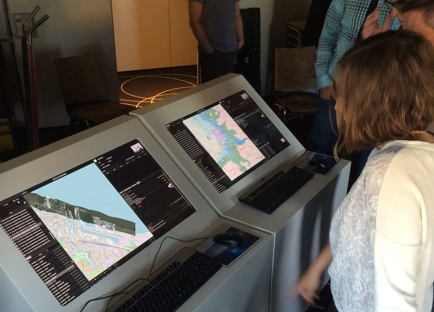
ISPRS Annals of the Photogrammetry, Remote Sensing and Spatial Information Sciences, Volume IV-1, 2018
ISPRS TC I Mid-term Symposium “Innovative Sensing – From Sensors to Methods and Applications”, 10–12 October 2018, Karlsruhe, Germany

sequent image analysis for real-time traffic monitoring applica-         these overlapping areas by determining appropriate (rectangular)
tions (Avbelj and Kurz, 2016, Kurz et al., 2012a). This system           image areas (respectively region of interest, ROI) for every single
transmitted the whole image to a ground station, which is - in           overlapping image.
combination with the used 54 MBit/s downlink - why the trig-
ger frequency of the aerial camera system was set to only about          3.2   Algorithm
0.1 Hz (Kurz et al., 2012b). A similar system is described by
Römer et al. in 2013, in which a bunch of on-board computers            The following algorithm determines sections for two overlapping
calculated rectified and JPG compressed ortho images, in order           aerial images, so that the overlapping area is minimized while
to send them via a data downlink to a ground station (Römer et          keeping a seamless coverage of the captured area between both
al., 2013). Here again, no overlap analysis or geometric clipping        (clipped) images. Lets assume two aerial images A and B and
was applied, thus full frame images had to be transmitted.               the position PA and PB and orientation OA and OB of the cor-
                                                                         responding camera at time of acquisition (see figure 1a). Further-
Another real-time mapping system was shown in 2016 within                more and without loss of generality1 lets assume, A and B have
the Clockwork Ocean project by IGI mbH (Helmholtz-Zentrum                an overlap within their captured area along their image’s y-axis,
Geesthacht, 2016). In this experiment, thermal airborne imagery          so that the upper region of A and the lower region of B captured
was mapped onto a moving map during flight. The images were              the same area on the ground (from slightly different perspectives).
not transmitted to a ground station, but presented to an on-board        The full frame areas are named roi(A) and roi(B). The opti-
operator. Unfortunately, IGI does not provide any information            mized sections roi0 (A) and roi0 (B) and their projections A0 and
about the applied mapping technology.                                    B 0 for both images, which minimize the overlapping area, result
                                                                         from following steps:
Kekec et al. proposed an approach of real-time mosaicing of
aerial images, which uses collision detection techniques to iden-
tify overlapping image sections (Kekec et al., 2014). A subse-             1. Determine horizontal geographic centre M between both
quent feature matching between those determined overlapping                   camera centres: M = (PA + PB )/2 (see figure 1b).
sections is then used for a continuous homography estimation
between a limited number of lastly captured aerial images. By              2. Determine base point M 0 on the elevation model’s surface
processing only potentially overlapping image sections and lim-               below M . This base point is formed by the horizontal com-
iting the number of pairwise matched images, computation effort               ponents (x, y) of M and the elevation E(M ) at M as de-
is minimized preserving real-time capabilities.                               fined by the applied elevation model as vertical component.
                                                                              This 3D point will serve as pivot element for the following
                                                                              intersection steps.
      3. TERRAIN AWARE IMAGE CLIPPING (TAC)
                                                                           3. Reproject M 0 back to both cameras sensors, yielding
3.1   Prerequisites                                                           one pixel coordinate for each aerial image pA (M 0 ) and
                                                                              pB (M 0 ).
The proposed algorithm is based on spatial intersection between
camera rays (i.e. rays of its corresponding pinhole camera model           4. Identify the horizontal pixel lines lA and lB in both images,
in space) and an elevation model of the captured area. It there-              containing the pixel coordinates pA (M 0 ) and pB (M 0 ). De-
fore requires an inner orientation (i.e. focal length, sensor size,           termine the four pixel rays r(lA1 ), r(lA2 ), r(lB1 ) and
optionally distortion model) of the applied camera(s), an exterior            r(lB2 ) of the lines’ endings, i.e. the rays of the left-most
orientation (i.e. position and orientation) for every single aerial           and the right-most pixel for each line lA and lB .
image and an existing terrain elevation model E, specifying an
elevation value for every two-dimensional geographic coordinate            5. Intersect the four obtained rays with the elevation model,
within the considered target area (i.e. E : R2 ⇒ R) (Hartley and              yielding four intersection points on ground IA1 , IA2 , IB1
Zisserman, 2004, Heckbert, 1989, Kannala and Brandt, 2006).                   and IB2 (see figure 1c).

Measurement of the exterior orientation is usually denoted as di-          6. Determine the two centre points C1 = (IA1 + IB1 )/2 and
rect georeferencing (Cramer et al., 2000, Cramer, 2001). It re-               C2 = (IA2 + IB2 )/2 between the previously calculated
lies on simultaneous determination and integration of the abso-               intersection points (see figure 1e).
lute 3D position by means of Global Navigation Satellite Systems           7. Reproject both ground points C1 and C2 back to both cam-
(GNSS) and the cameras orientation measured by inertial sensors               era sensors, thus obtaining four pixel coordinates, two for
(IMU). Since we do not rely on subsequent bundle adjustment in                each image, pA (C1 ), pA (C2 ), pB (C1 ) and pB (C2 ).
our real-time applications, we require that the accuracy of direct
georeferencing has to be sufficient enough to enable seamless im-          8. Section roi0 (A) for A results from smallest lower area of A,
age mosaics. The projection accuracy depends primarily on mea-                which contains pA (C1 ) and pA (C2 ). Section roi0 (B) for
surement accuracy of inertial sensor, on flight altitude (i.e. height         B results accordingly from smallest upper area of B, which
above ground), cameras angle of view and the precision of the                 contains pB (C1 ) and pB (C2 ). Note: since the described
applied elevation model. The inertial sensor and elevation model              algorithm minimizes the overlap just along the image’s y-
we applied for our evaluations are noted in section 4.                        axis, both picture sections extend from left-most side of the
                                                                              image to the right-most side. The upper section includes the
Intersecting all four sensor corner rays of an aerial image with              first row, the lower section the last pixel row (see figure 1f).
a given elevation model results in a rough footprint approxima-
tion of the images’ captured area. Generally, the footprints of
two consecutively recorded aerial images overlap more or less,
depending on aforementioned conditions (Hein et al., 2017, Sny-
der, 1987). The aim of the algorithm we propose is to cut out               1 refer   section 3.4

             This contribution has been peer-reviewed. The double-blind peer-review was conducted on the basis of the full paper.
                             https://doi.org/10.5194/isprs-annals-IV-1-61-2018 | © Authors 2018. CC BY 4.0 License.                        62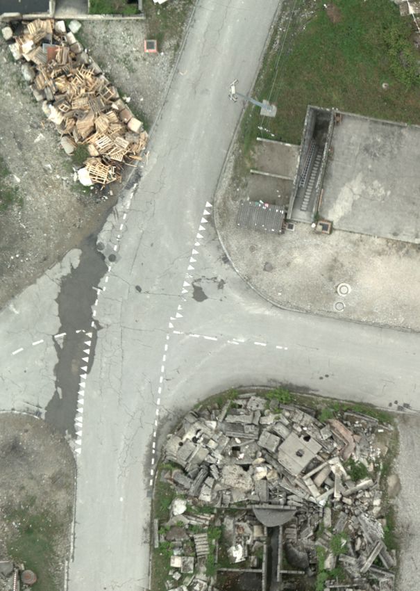
ISPRS Annals of the Photogrammetry, Remote Sensing and Spatial Information Sciences, Volume IV-1, 2018
ISPRS TC I Mid-term Symposium “Innovative Sensing – From Sensors to Methods and Applications”, 10–12 October 2018, Karlsruhe, Germany

                                  PB                        PA
                                                                                                          r(l B2) r(lA1)

                roi(B)
                                                                 roi(A)
                                                                                                                                r(lA2 )

                                                                                              r(l B1)
                                                                                                                        I B2    IA2

               B
                                                                                                                   M'

                                                                            A

                                                                                               IA1 IB1
                                           a)                                                                 d)

                                  PB        M               PA

                   p(M')                                    p(M')
                                                            A
                                                                                                              pA(C2)           pB(C2)
                    B

                   lB
                                                                       lA                     pA(C1)                pB(C1)

                                                                                                                        IB2 C2 I
                                                                                                                                A2

                                                M'

                                                                                              IA1 C I
                                                                                                   1 B1

                                           b)                                                                 e)

                                       r(l B2) r(lA1)

                                                                                         roi'(B)              pA(C2)           pB(C2)

                                                                                                pA(C1)                          roi'(A)
                                                                                                                    pB(C1)
                                                                 r(lA2 )

                        r(l B1)
                                                     I B2        IA2

                                                                                        B'
                                                M'

                                                                                                                                          A'

                         IA1 IB1

                                           c)                                                                 f)

Figure 1. Terrain aware image clipping (TAC) algorithm: a) Full frame projection of two overlapping aerial images.
  b) Projection M 0 of centre M between both cameras and reprojection of M 0 into both sensors (pA (M 0 ) and pB (M 0 )) and corre-
  sponding sensor lines lA and lB . c) Projection of sensor line endings to the ground IA1 , IA2 , IB1 and IB2 .
  d) Cropping of aerial images by application of lA and lB and their projections. e) Determination of centres C1 and C2 between line
  endings of projection of lA and lB and reprojection of C1 and C2 into sensors pA (C1 ), pA (C2 ), pB (C1 ) and pB (C2 ).
  f) Final clipping roi0 (A) and roi0 (B) by application of these reprojection points and their projections.

            This contribution has been peer-reviewed. The double-blind peer-review was conducted on the basis of the full paper.
                            https://doi.org/10.5194/isprs-annals-IV-1-61-2018 | © Authors 2018. CC BY 4.0 License.                             63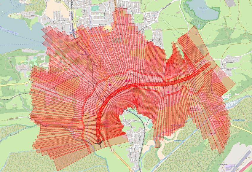
ISPRS Annals of the Photogrammetry, Remote Sensing and Spatial Information Sciences, Volume IV-1, 2018
ISPRS TC I Mid-term Symposium “Innovative Sensing – From Sensors to Methods and Applications”, 10–12 October 2018, Karlsruhe, Germany

While the first three steps roughly generate a first ’marker’ for a           the overlapping image edges or the translation axes between both
potential ’cutting line’ in both images, the next four steps (4.-7.)          images. Generally, the algorithm applies for any configuration of
serve as a refinement of this cutting line. Without this refinement,          two overlapping aerial images, including images from different
possible rotations, in particular around the vertical (yaw) axis,             camera sensors and even oblique set-ups. The corresponding axes
between A and B could result in gaps in between clipped images                and directions, along which the overlapping is to be optimized,
at the edges (see figure 1d). This refinement ensures a seamless              define the mapping between the camera set-up and the formalized
coverage of the clipped images even at the edges by ’widening’                elements in the described algorithm.
both picture sections, if necessary (see figure 1f).

3.3    Generating maps                                                                                   4. RESULTS

By repeated application of this procedure for every pair of con-              For all samples, applications and demonstrations referred in this
secutively recorded aerial images, the overlapping image areas                paper we used the SRTM-90 dataset as elevation model (The
are minimized while keeping a seamless coverage of the whole                  Shuttle Radar Topography Mission (SRTM), 2000). It covers the
captured area. Figure 2 illustrates the overlap minimization for              entire globe and is free of charge. Nevertheless, other (e.g. more
consecutively captured aerial images in profile view. Figure 3                precise) elevation models could be used as well. In general, a
demonstrates a sample scene and the application of the algorithm              more precise elevation model will increase projection accuracy,
with a before-and-after comparison. The scene comprises 392                   particularly in mountainous terrain. However, when using nadir
aerial images (6.15 billion pixels = 11.5 GB raw data), taken                 aerial images, i.e. the angle of view is near to perpendicular axis,
with a triple sensor camera head (oblique leftwards, nadir cen-               height errors will only have a moderate effect on the result.
tre, oblique rightwards). The upper image displays the raw (full
frame) overlapping footprints of all aerial images. The second                The nadir mounted camera systems we used so far were
image displays the full frame projection of all images. The third             all equipped with high-grade2 GNSS receiver and mid-grade3
image shows the footprints after application of the presented al-             MEMS-based IMU sensors, resulting in a typical projection pre-
gorithm. The lower image shows the textured footprints. Our                   cision in the order of decimetres at flight levels of about 300...500
algorithms reduced the data size of the overall image mosaic by               metres above ground, referred to consecutive images. The abso-
about 86% (resulting in 873 million pixels = 1.6 GB raw data).                lute positional accuracy of direct georeferencing with the afore-
Note, that in this sample some areas at the borders are not covered           mentioned set-up has been evaluated in (Brauchle et al., 2018).
after image clipping. This effect may occur in cases of stronger              It states a typical horizontal position error of less than 2 metres
alternating roll angles. For standard meandering straight flight              for the configuration with a standard utility aircraft and a flight
lines with a more or less steady roll attitude, covered areas will            altitude of 2, 600f t (approx. 780m) above ground.
not be affected.
                                                                              4.1   Comparison
                      aerial camera positions and orientations
                                                                              We further evaluated processing time and results of generating
                                                                              quick orthophoto mosaics between our approach and two com-
                                                                              mercial photogrammetric solutions AgiSoft PhotoScan Profes-
                                                                              sional4 and Pix4DMapper5 , which implement a structure-from-
                                                                              motion (SfM) based approach (Tomasi and Kanade, 1992).

                                                                              The sample scene comprises 254 aerial images, each with a res-
                                                                              olution of 4864x3232 pixels (16MPix) and 12bit radiometric
elevation model
                                                                              depth, provided as 16bit tiff images. The average spacial reso-
                                                                              lution (ground sampling distance, GSD) is about 2.7cm, the cap-
                                                                              tured area is about 464m x 607m (0.28km2 ). Each approach
                                                                              was provided the very same input data, which consists of 254 tiff
                                                                              images, a WGS84 position and orientation6 for each image file
                                                                              and nominal camera parameters such as pixel pitch, sensor size
                                                                              and focal length. In both commercial tools, each setting was set
                                                                              to the fastest option, which means in particular no color correc-
                                                                              tion, no compression and no hole fittings where available. No
elevation model
                                                                              ground control points (GCPs) were used. The GSD of the to be
                                                                              generated orthophoto mosaic image was set to native resolution
                                                                              of about 2.7cm per pixel. All tests where performed on the same
Figure 2. Aerial imaging of mountainous terrain and overlap vi-
                                                                              machine, a decent workstation with a NVidia GTX1070 graphics
  sualization of its view cones (profile view).
                                                                              card, which is used by AgiSoft and Pix4DMapper for hardware
  Upper figure: full frame coverage and view cone overlap.
                                                                              accelerated image processing steps. For each tool, the overall
  Lower figure: minimized view cone overlap of clipped aerial
                                                                              processing duration was measured from image loading up to the
  images by application of TAC algorithm.
                                                                              completion of orthophoto mosaic export. Finally, all approaches
                                                                              generated a georeferenced orthophoto mosaic as tiff image file
                                                                                 2 realtime kinematic capable L1/L2/L5
3.4    Additional remarks                                                        3 RMS  attitude accuracy: roll/pitch: 0.015 deg; heading: 0.080 deg
                                                                                 4 AgiSoft PhotoScan Professional v.1.3.5 build 5649
The proposed algorithm states some presuppositions, regarding                    5 Pix4DMapper v4.2.26

the relative arrangement of any two overlapping images, such as                  6 RTK solution, no GPS/INS post processing

                  This contribution has been peer-reviewed. The double-blind peer-review was conducted on the basis of the full paper.
                                  https://doi.org/10.5194/isprs-annals-IV-1-61-2018 | © Authors 2018. CC BY 4.0 License.                               64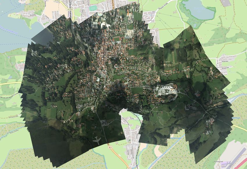
ISPRS Annals of the Photogrammetry, Remote Sensing and Spatial Information Sciences, Volume IV-1, 2018
ISPRS TC I Mid-term Symposium “Innovative Sensing – From Sensors to Methods and Applications”, 10–12 October 2018, Karlsruhe, Germany
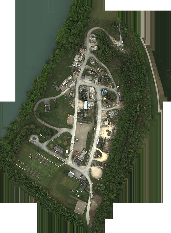
with a resolution of about 16.000 x 23.000 pixels. Regarding po-
sitional accuracy, all mosaics coincide with a maximum variation
below 2 metres. Due to the lack of GCPs, an absolute position ac-
curacy evaluation was not performed. The generated mosaics are
shown in figure 4, the corresponding processing times are shown
in figure 5.
As seen in figure 5, both commercial solutions required con-
siderably more time to complete the orthophoto mosaic gener-
ation. This is particularly due to the expensive pixel based im-
age co-registration steps, which are required by both SfM-based
approaches. In contrast, TAC relies completely on direct geo-
referencing solution, thus does not perform any computer vision
processing. In fact, generating orthophoto mosaics with TAC is
hardly more then successively non-affine transformed painting of
clipped aerial images.
5. APPLICATION
There are two kinds of application that benefit from TAC algo-
rithm: Rapid mapping applications, providing a fast aerial per-
spective situation picture and real-time mapping applications,
which require instantaneous mapping and possibly image data
transmission during flight. The proposed method was imple-
mented and successfully tested within both scenarios, which is
presented in the following.
5.1 Rapid Mapping
The presented algorithm allows for generating quick orthophoto
mosaics of captured areas. Since it prefers the nadir looking im-
age parts of overlapping aerial images, it reduces occlusion ef-
fects caused by adverse perspectives. Furthermore, in the case of
nadir mounted cameras, the algorithm generally favours central
image areas. This minimizes geometric discontinuities between
adjacent images caused by radial distortion. Finally, central im-
age parts are generally less affected by vignetting effects, thus
resulting in radiometrically more homogeneous mosaics.
The algorithm is implemented and part of the MACS-SaR rapid
mapping system for disaster management (Hein et al., 2017).
This system was demonstrated and successfully evaluated for
search-and-rescue missions within an international rescue exer-
cise ACHILLES 2017 led by the United Nations in Switzerland
(NRZ, 2017). It enables generation and visualization of high-
resolution aerial maps of captured areas up to several square kilo-
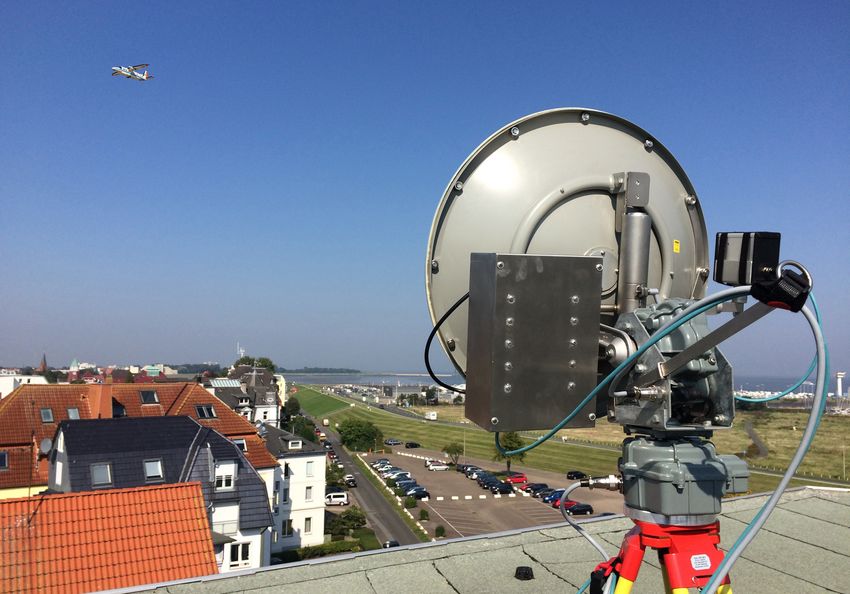
metres within minutes after landing. Figure 6 shows the UAV
carrying aerial camera system, purpose-built for rapid mapping
applications, and the usage of on-site generated maps for disaster
assessment, coordination and management tasks. In total, during
this exercise several regions with a size of some square kilometres
were captured in a few thousand aerial images. For each region
an aerial map was generated immediately after landing and dis-
tributed to the task forces (Kraft et al., 2018).
5.2 Real-time Mapping
Figure 3. Map generation using TAC algorithm: Sample scene
comprising 392 aerial images, captured by a triple sensor cam- When it comes to real-time mapping with application of (capacity
era head. Full footprint rendering (upper images) and clipped limited) broadband data downlinks, the presented algorithm pro-
images by TAC algorithm (lower images). By application of vides a redundancy optimized selection of image data. Thus, im-
TAC algorithm, image data to be rendered was reduced by 86%. age data to be transmitted is reduced to a minimum, while keep-
ing full coverage and full geometric and radiometric resolution of
the images.
This contribution has been peer-reviewed. The double-blind peer-review was conducted on the basis of the full paper.
https://doi.org/10.5194/isprs-annals-IV-1-61-2018 | © Authors 2018. CC BY 4.0 License. 65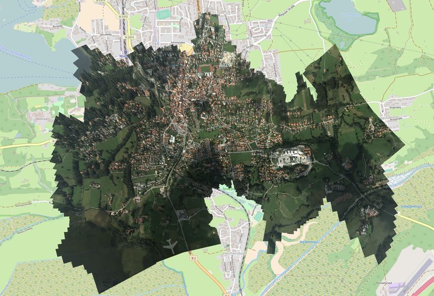
ISPRS Annals of the Photogrammetry, Remote Sensing and Spatial Information Sciences, Volume IV-1, 2018
ISPRS TC I Mid-term Symposium “Innovative Sensing – From Sensors to Methods and Applications”, 10–12 October 2018, Karlsruhe, Germany

Figure 4. Quick orthophoto mosaic comparison: Results for a             Figure 6. Rapid mapping with TAC algorithm for disaster man-
  sample scene of 0, 28km2 , comprising 254 aerial images with            agement: International rescue exercise ACHILLES 2017 led
  an average GSD of 2.7cm. Left: full scene, Right: detail view.          by the UN in Switzerland with application of an integrated
  Top: Pix4DMapper, Center: Agisoft PhotoScan Professional,               rapid mapping system. Autonomous UAV (maximum take-off
  Bottom: Quick mosaic generated with TAC algorithm. Pro-                 weight: 14kg, wingspan: 3, 50m, vertical take-off and land-
  cessing times shown in figure 5.                                        ing) with MACS aerial camera system and mobile map viewer
                                                                          for disaster assessment, analysis and coordination.

                                                                        A streaming version of the TAC algorithm clips every recorded
  Pix4D                                               34:09 mins        image in consideration of its previous and its subsequent cap-
AgiSoft                              20:42 mins                         tured image, before it is compressed and transmitted via a data
                                                                        downlink. This procedure was implemented and demonstrated
    TAC       2:40 mins                                                 within a real-time monitoring experiment in August 2017 over
                                                                        the North Sea off Cuxhaven, Germany (Brauchle et al., 2017).
                                                                        It was shown, that the redundancy optimized image data allows
Figure 5. Processing times for generating quick orthophoto mo-          a seamless real-time mapping of the recorded area with full ge-
  saics shown in figure 4. The times include the complete pro-          ometric and radiometric resolution through an average data link
  cessing chain, from loading the 254 tiff images up to comple-         rate of about 5-10 MBit/s. Throughout the entire experiment,
  tion of orthophoto mosaic export.                                     roughly 12 GB of raw image data was transmitted via the down-

            This contribution has been peer-reviewed. The double-blind peer-review was conducted on the basis of the full paper.
                            https://doi.org/10.5194/isprs-annals-IV-1-61-2018 | © Authors 2018. CC BY 4.0 License.                  66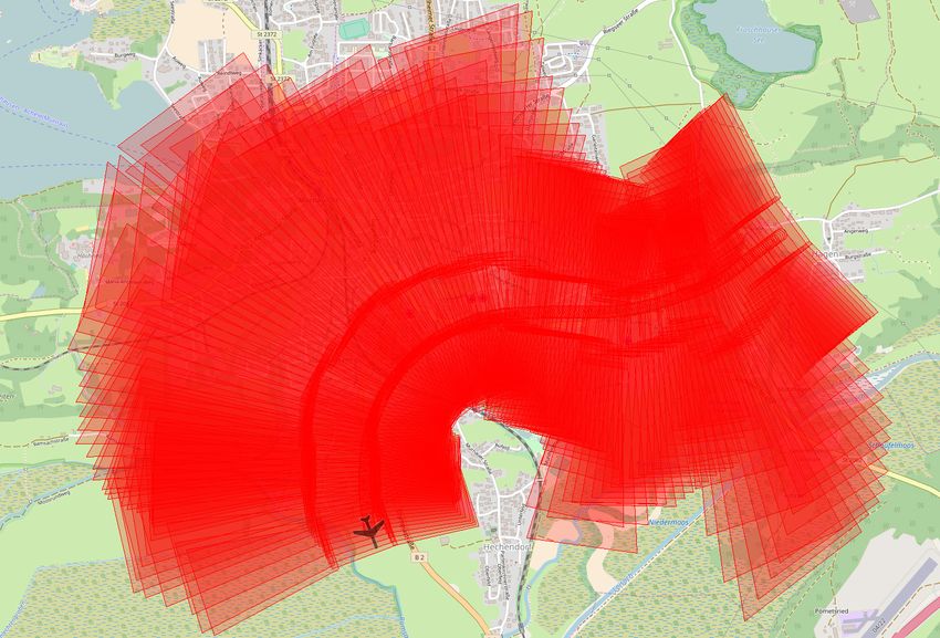
ISPRS Annals of the Photogrammetry, Remote Sensing and Spatial Information Sciences, Volume IV-1, 2018
ISPRS TC I Mid-term Symposium “Innovative Sensing – From Sensors to Methods and Applications”, 10–12 October 2018, Karlsruhe, Germany

                                                                         with constant time complexity and does not require any image
                                                                         analysis, which allows its application even on lightweight embed-
                                                                         ded imaging systems like small UAV-based aerial cameras. Given
                                                                         a sufficient position and orientation quality, seamless orthophoto
                                                                         mosaics can be generated significantly faster than structure-from-
                                                                         motion based approaches - without any need of accelerating hard-
                                                                         ware.

                                                                         However, several approaches may extend the range of applica-
                                                                         tion and are currently discussed and tested. The proposed algo-
                                                                         rithm prefers nadir views over oblique image areas. In the case
                                                                         of oblique aerial imaging with focus on e.g. façade visualization,
                                                                         the proposed pivot element M 0 could be replaced by any other
                                                                         non-nadir surface point. This pivot element could even be deter-
                                                                         mined by a pixel ray of a specified angle of view.

                                                                         The proposed algorithm is currently applied only on pairs of con-
                                                                         secutively recorded images. In case of meandering flight patterns
                                                                         or even arbitrary arranged sets of aerial images covering a com-
                                                                         mon area, one may intersect any overlapping pair of aerial images
                                                                         to optimize image areas to be rendered. Data structures like quad-
                                                                         trees make it easy and fast to find overlapping images within the
                                                                         set.

                                                                         Another extension to our basic approach addresses the granularity
                                                                         of geometric projection. While the currently proposed algorithm
                                                                         extracts one (rectangular) section for every single aerial image,
                                                                         a ”tiling version” of this algorithm, possibly supporting level-
                                                                         of-detail techniques, could extract several (distinct) image areas
                                                                         and their projection. This would increase the positional accuracy
                                                                         of computed projections, in particular for highly structured areas
                                                                         like mountains or deep valleys.
Figure 7. Real-time mapping using TAC algorithm: Aerial im-
  ages are captured, clipped and transmitted via a 10 MBit/s data
                                                                         Furthermore, the current implementations do not apply any fur-
  downlink to a ground station (upper figure), where mapping
                                                                         ther image registration procedures. Similar to the approach of
  software generates seamless aerial maps from the transmitted
                                                                         Kekec et. al (Kekec et al., 2014), lightweight image matching
  image data (lower figure). The latency between image acquisi-
                                                                         methods could be used to enhance the real-time georeferencing
  tion and visualization is about 2 seconds.
                                                                         solution. The overlap analysis done with our algorithm could
                                                                         limit the image parts to be analysed, which in turn would mini-
                                                                         mize computational effort for the image co-registration methods.
link. From these image data, real-time aerial maps were continu-
ously rendered in the ground station, spanning a covered area of
                                                                         Finally, we are evaluating the application of fast and lightweight
more than 100 square kilometres (see figure 7).
                                                                         sparse matching techniques to derive an approximate elevation
                                                                         model in real-time. This could eliminate the need for a priori
            6. CONCLUSION AND OUTLOOK                                    knowledge of a terrain elevation model of the area to be captured.
                                                                         Furthermore, such a real-time derived height model providing
                                                                         better spatial resolution could also enhance the overall quality of
The proposed algorithm reduces redundancies of overlapping
                                                                         generated maps and further derived geospatial data products.
aerial imagery for rapid mapping purposes. Depending on the
degree of overlap it may considerably reduce the amount of im-
age data to be rendered or to be transmitted (in case of applica-
tions requiring data transmission links), while keeping a seam-
less coverage of the captured area. At the same time, due to the
preference for central image areas, it may increase the quality                                    REFERENCES
of generated maps in terms of radiometric homogeneity and / or
geometric accuracy. The algorithm was implemented and tested             Agisoft LLC, Russia, 2018. Agisoft PhotoScan Professional.
for various platforms and use cases. It was successfully demon-          https://www.agisoft.com.
strated within several projects, ranging from rapid mapping appli-
cations, such as on-site disaster management support to real-time        Avbelj, J. and Kurz, F., 2016. Airborne real-time mapping and
                                                                         monitoring. In: 44th Slovenian Land Surveying Day.
applications using data downlinks for just-in-time aerial map gen-
eration and visualization. It is applicable for any set-up of aerial     Brauchle, J., Bayer, S. and Berger, R., 2017. Automatic ship de-
camera system, which provides a (approximate) pinhole camera             tection on multispectral and thermal infrared aerial images using
model and a position and orientation date (direct georeferencing)        MACS-Mar remote sensing platform. In: S. Satoh, C.-W. Ngo
for every captured image to be rendered and / or transmitted. Fur-       and J. Yuan (eds), Pacific-Rim Symposium on Image and Video
thermore, the algorithm has a very small computational footprint         Technology (PSIVT 2017), Springer Science.

             This contribution has been peer-reviewed. The double-blind peer-review was conducted on the basis of the full paper.
                             https://doi.org/10.5194/isprs-annals-IV-1-61-2018 | © Authors 2018. CC BY 4.0 License.                      67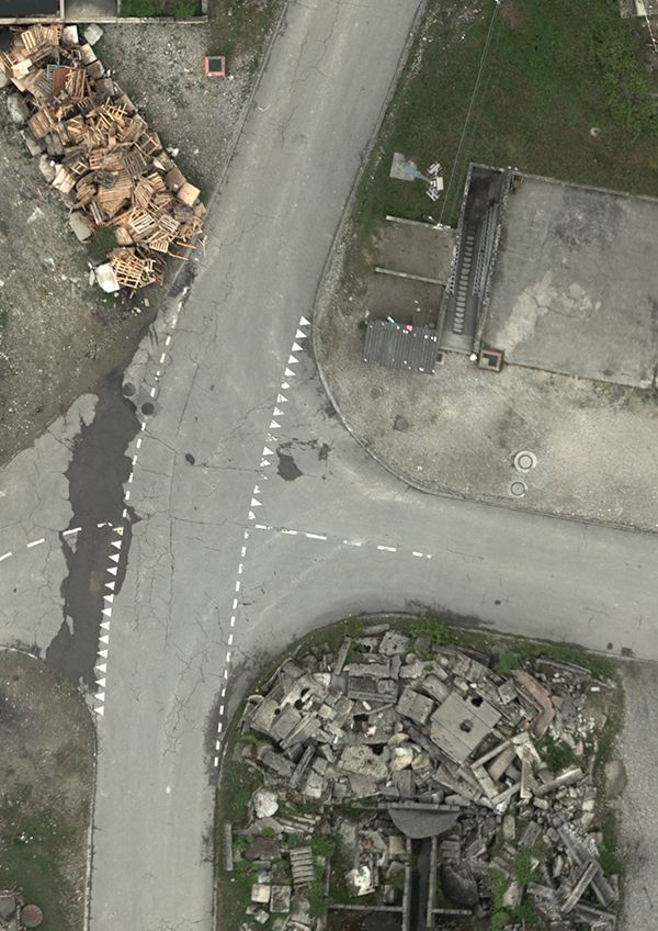
ISPRS Annals of the Photogrammetry, Remote Sensing and Spatial Information Sciences, Volume IV-1, 2018
ISPRS TC I Mid-term Symposium “Innovative Sensing – From Sensors to Methods and Applications”, 10–12 October 2018, Karlsruhe, Germany

Brauchle, J., Bayer, S., Hein, D., Berger, R. and Pless, S., 2018.       NRZ, 2017.        I.S.A.R. Germany bei 72-Stunden-Übung.
Macs-mar: A real-time remote sensing system for maritime se-             http://www.nrz.de/staedte/kleve-und-umland/i-s-a-r-bei-72-
curity applications. CEAS Space Journal.                                 stunden-uebung-id210088203.html.

CGI Systems GmbH, Germany, 2018. Geomatica OrthoEngine.                  Pix4D SA, Switzerland, 2018. Pix4Dmapper. https://pix4d.com.
http://www.cgisystems.de.
                                                                         Pravenaa, S., 2016. A methodical review on image stitching and
Cramer, M., 2001. On the use of direct georeferencing in air-            video stitching techniques.
borne photogrammetry. In: Proceedings 3rd. International Sym-
posium on Mobile Mapping Technology, January 2001, Cairo,                PrecisionHawk Inc., North Carolina, 2018. PrecisionHawk Pre-
digital publication on CD.                                               cisionMapper. http://www.precisionhawk.com.
                                                                         Römer, H., Kersten, J., Kiefl, R., Plattner, S., Mager, A. and
Cramer, M., Stallmann, D. and Haala, N., 2000. Direct georefer-
                                                                         Voigt, S., 2013. Airborne near real-time monitoring of assembly
encing using gps/inertial exterior orientations for photogrammet-
                                                                         and parking areas in case of large scale public events and natu-
ric applications. In: International Archives of Photogrammetry
                                                                         ral disasters. International Journal of Geographical Information
and Remote Sensing, Vol. 33 Part B3, pp. 198–205.
                                                                         Science 28(4), pp. 682–699.
Cubic MotionDSP Inc., C., 2018. Real-time 2D maps from full              The Shuttle Radar Topography Mission (SRTM), 2000.
motion video. https://www.motiondsp.com/2d-mapping/.                     http://www2.jpl.nasa.gov/srtm (Feb. 2000).
ESRI Inc., California,        2018a.          ESRI    Drone2Map.         Snyder, J. P., 1987. Map projections – A working manual. U.S.
https://www.esri.com.                                                    Geological Survey professional paper, U.S. Government Printing
                                                                         Office.
ESRI Inc., California, 2018b. ESRI Ortho Mapping in ArcGIS
Pro. https://www.esri.com.                                               Tjahjadi, M., Handoko, F. and Sai, S., 2017. Novel image
                                                                         mosaicking of UAV’s imagery using collinearity condition. 7,
Ghosh, D. and Kaabouch, N., 2016. A survey on image mo-                  pp. 1188–1196.
saicing techniques. Journal of Visual Communication and Image
Representation 34, pp. 1 – 11.                                           Tomasi, C. and Kanade, T., 1992. Shape and motion from image
                                                                         streams under orthography: a factorization method. International
Hartley, R. and Zisserman, A., 2004. Multiple View Geometry in           Journal of Computer Vision 9(2), pp. 137–154.
Computer Vision. Second edn, Cambridge University Press.
                                                                         Trimble Inc., California, 2018.                Inpho       UASMaster.
Heckbert, P., 1989. Projective mappings for image warping. In:           https://geospatial.trimble.com.
In in Fundamentals of Texture Mapping and Image Warping (Paul
Heckbert, Masters Thesis), UC.                                           Vexcel Imaging GmbH, Austria,               2018.           UltraMap.
                                                                         http://www.vexcel-imaging.com.
Hein, D., Bayer, S., Berger, R., Kraft, T. and Lesmeister, D.,
2017. An integrated rapid mapping system for disaster manage-
ment. ISPRS - International Archives of the Photogrammetry,
Remote Sensing and Spatial Information Sciences XLII-1/W1,
pp. 499–504.

Helmholtz-Zentrum Geesthacht, 2016. Expedition Clockwork
Ocean. http://www.uhrwerk-ozean.de.

Kannala, J. and Brandt, S. S., 2006. A generic camera model
and calibration method for conventional, wide-angle, and fish-
eye lenses. IEEE Transactions on Pattern Analysis and Machine
Intelligence 28(8), pp. 1335–1340.

Kekec, T., Yildirim, A. and Unel, M., 2014. A new approach to
real-time mosaicing of aerial images. Robotics and Autonomous
Systems 62(12), pp. 1755 – 1767.

Kraft, T., Bayer, S., Hein, D., Stebner, K., Lesmeister, D. and
Berger, R., 2018. Echtzeit-Lagekarten für die Katastrophen-
hilfe. UAV 2018 Vermessung mit unbemannten Flugsystemen
89, pp. 123–135.

Kurz, F., Meynberg, O., Rosenbaum, D., Türmer, S., Reinartz,
P. and Schroeder, M., 2012a. Low-cost optical camera sys-
tems for disaster monitoring. In: XXII International Society for
Photogrammetry & Remote Sensing Congress, Vol. XXXIX-B8,
pp. 33–37.

Kurz, F., Türmer, S., Meynberg, O., Rosenbaum, D., Runge, H.,
Reinartz, P. and Leitloff, J., 2012b. Low-cost optical camera sys-
tem for real-time mapping applications. Photogrammetrie Fern-
erkundung Geoinformation Jahrgang 2012(2), pp. 159–176.

nFrames GmbH, Germany,              2018.          SURE      Aerial.
http://www.nframes.com.

             This contribution has been peer-reviewed. The double-blind peer-review was conducted on the basis of the full paper.
                             https://doi.org/10.5194/isprs-annals-IV-1-61-2018 | © Authors 2018. CC BY 4.0 License.                         68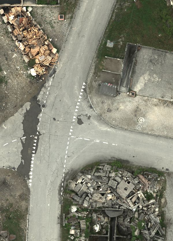
You can also read