A Low Energy FPGA Platform for Real-Time Event-Based Control - Schloss ...
←
→
Page content transcription
If your browser does not render page correctly, please read the page content below
A Low Energy FPGA Platform for Real-Time
Event-Based Control
Silvano Seva
DEIB, Politecnico di Milano, Italy
silvano.seva@polimi.it
Claudia Esther Lukaschewsky Mauriziano
Graduate student at Politecnico di Milano, Italy
claudia.lukaschewsky@mail.polimi.it
William Fornaciari
DEIB, Politecnico di Milano, Italy
william.fornaciari@polimi.it
Alberto Leva
DEIB, Politecnico di Milano, Italy
alberto.leva@polimi.it

      Abstract
    We present a wireless sensor node suitable for event-based real-time control networks. The node
achieves low-power operation thanks to tight clock synchronisation with the network master (at
present we refer to a star network but extensions are envisaged). Also, the node does not employ
any programmable device but rather an FPGA, thus being inherently immune to attacks based on
code tampering. Experimental results on a simple laboratory apparatus are presented.

2012 ACM Subject Classification Hardware → Wireless integrated network sensors; Computer
systems organization → Embedded and cyber-physical systems

Keywords and phrases real-time, event-based control, FPGA, wireless control networks

Digital Object Identifier 10.4230/OASIcs.NG-RES.2020.4

 1      Introduction
Nowadays many control systems operate through a (partially) wireless network, and this
will most likely become more and more frequent in the future. It is therefore expected that
hardware and software architectures both support and foster this tendency, by allowing
non-networked and/or wired existing solutions to transition toward the wireless network
world in as seamless a manner as possible, and by prying the maximum advantage out of
going networked, and above all wireless.
    Restricting now the focus to the wireless case consistently with the scope of the paper,
the important matter just mentioned has several facets, from resilience to communication
deficiencies through bandwidth and energy efficiency up to security. These facets stem from
two main motivations: the adoption of an inherently shared, disturbance-prone and publicly
accessible medium as the radio, and the widespread use of battery-operated devices to reduce
wiring as much as possible. And needless to say, the issues just sketched are to be addressed
while offering real-time capabilities sharp enough for the intended application.
    In this paper, which is part of a long-term research activity on networked event-based
real-time control, we present a sensor node designed to operate in the context just mentioned,
and we provide two main contributions. The first one is implementing a sensing device
suitable for the particular event-based control technique presented in [15]. The second one is
realising the said sensor using only hardware elements, without the involvement of software
parts. The complete absence of any microcontroller or soft-core in the favour of a device
           © Silvano Seva, Claudia Esther Lukaschewsky Mauriziano, William Fornaciari, and Alberto Leva;
           licensed under Creative Commons License CC-BY
Workshop on Next Generation Real-Time Embedded Systems (NG-RES 2020).
Editors: Marko Bertogna and Federico Terraneo; Article No. 4; pp. 4:1–4:11
                   OpenAccess Series in Informatics
                   Schloss Dagstuhl – Leibniz-Zentrum für Informatik, Dagstuhl Publishing, Germany
4:2 A Low Energy FPGA Platform for Real-Time Event-Based Control
completely based on hardwired logic – besides proving that the complexity of the designed
solution is adequate for an FPGA, and prospectively for an ASIC – brings about two main
advantages. The first one is related to power consumption, as it is well known that an ASIC
absorbs far less current1 with respect to a microcontroller. This claim grounds on two main
considerations: first of all, an ASIC-based device contains only the logic circuits necessary
to perform its functionalities, while a microcontroller has different peripherals which, even
when not in use, consume power. Then, coming to the technological side, in the fabrication
process of an ASIC suitable techniques can be exploited to significantly reduce the power
consumption, e.g. minimising the transistors’ leakage current. A microcontroller, on the
other hand, – being a pre-manufactured device – cannot be made as low power as needed, if
not by going through a customised fabrication process.
The other advantage of using an hardwired control logic, most important for a safe
operation in an IIoT context or in an industrial control network at large, is that it allows to
have a strong resilience in the face of possible malicious attacks. This is because there is
no way of altering the device’s behaviour by reprogramming it, for the trivial reason that
there is nothing to reprogram. In fact one may still think of re-configuring the FPGA, but
first this is enormously more difficult than tampering with the code of a microcontroller, and
then the same operation would be impossible if the design was turned into an ASIC. This is
a key feature of our proposal, since in an “interconnected manufacturing” world, a damage
to the communication infrastructures can lead to incidents and loss of equipment, also of
huge extent.
As for the structure of the control networks which the presented device will be part
of, at present we only target the star topology. This limitation is for the moment deemed
acceptable, being also shared by several alternatives in the literature – like, e.g., the schemes
presented in [9] and [8]. Thanks to the tight clock synchronisation technique on which our
solution is based, however, we are confident that the above limitation will be released in
future extensions, making it possible to realise real-time mesh wireless control networks.
The paper is organised as follows. After a brief literature review, we give a detailed
description of the devised sensor node. Finally, an closed-loop experiment aimed at validating
a prototype of the device is presented, alongside with a brief analysis the obtained results.
2 Related work
Most typically, digital controls are realised with periodic sampling. In recent years, however,
event-based control (EBC) has emerged as a valid alternative in which control signals are
instead computed “only when needed” [1, 2]. On the methodological side EBC requires a
specialised theory to handle non uniform sampling [3] and guarantee stability properties [4],
but its impact is evident also from the technological standpoint.
Focusing on this second aspect, in some cases EBC is viewed as a means to respond to
an event immediately and not at the first sampling time following that event [10]2 . In some
others it is viewed as a means for a periodic controller to skip the control signal computation
1
It is common practice to talk about “current” instead of “power” consumption because the time integral
of current, irrespective of the voltage that instead enters in the computation of power, directly provides
the charge extracted from the battery, that can be easily compared against its capacity (correspondingly
expressed in current-by-time units) to estimate the feasible device operation time before the battery
needs replacing.
2
Rigorously speaking this is true only for continuous-time EBC, but it can be reasonably assumed to
hold also for fast-clocked event generators.S. Seva, C. E. Lukaschewsky Mauriziano, W. Fornaciari, and A. Leva 4:3
at some steps, in this case setting the clock of the event generator equal to that of the
sampling – a particularly interesting feature wherever computational workloads are not
negligible with respect to the control period [12]. And besides the above, the interest of EBC
for real-time applications is testified by works such as [17] and many others: a survey can be
found in [16].
Even more important is nowadays the conjunction of EBC and wireless control applications,
where strict requirements in terms of energy and bandwidth consumption have to be faced,
especially with battery-operated devices. The (wider) problem of energy efficiency in wireless
devices for control has been addressed in works like [7, 13, 14], while specific reference to EBC
is made e.g. in [20, 6, 5], and architectural aspects are investigated in works like [24, 23].
We have at this point to notice that the quoted research, when talking about “savings”,
tends to overlap bandwidth and energy saving [18]. This is legitimate and sensible, as less
transmissions apparently achieve both objectives, but as EBC entails transmissions at a
priori unknown instants, care has to be taken to both preserve the required timing and
synchronisation properties [19] and minimise information losses due to network collisions [11].
Based on the minimum review above, we can conclude that a wireless device capable
of low-power event generation with guarantees on the channel occupation instants would
certainly provide a contribution to the problems above.
3 Platform description
This section describes in detail the structure of the device presented in this paper. First of
all we give an overview of the assumptions we made about the network in which the node
operates. Then, a functional description is given, followed by an in-depth description of some
of the subsystems.
3.1 Network assumptions
The device presented in this treatise has been designed to be part of a wireless network
fulfilling these requirements:
all the network elements must consume as less power as possible,
the transmission jitter of each data packet must be as low as possible to minimise the
impact on the stability degree of the closed loop system.
Both these requirements can be accomplished using a Time Division Multiple Access
(TDMA) network scheme, where each node can transmit and receive data only in prescribed
time slots, assigned and known network-wide. This scheme proves to be effective for several
aspects: as regards the power consumption, a TDMA approach allows each node to turn off
its radio transceiver – meaning that the node cannot transmit nor receive any data packet –
whenever its operation is not necessary. Each device, then, keeps its radio transceiver off
except in correspondence of its time slots and only if there is data to send. The transceiver
is also turned on periodically, to synchronise the device with the master node. In this latter
case, energy saving is maximised when suitable synchronisation schemes are used – like the
one presented in [22] – where, to synchronise, each device has to activate its radio transceiver
for a very short period (in the order of the tenths of milliseconds) once every 60 seconds or so.
The use of a properly synchronised TDMA scheme allows also to sensibly reduce the packet
transmission jitter, both reducing the variability of the transmission period and avoiding
collisions.
NG-RES 20204:4 A Low Energy FPGA Platform for Real-Time Event-Based Control
3.2 Functional description
The device is composed of a printed circuit board carrying three main functional elements:
the sensing unit,
a radio transceiver,
and the control logic that manages all their functionalities.
In turn, the control logic is partitioned into three main functional blocks:
one to manage the sensing unit and the event generation,
one in charge of controlling the radio transceiver,
and a supervising one.
The overall structure is subdivided in functional subsystems, summarised in Figure 1.
The internals and the behaviour of the contained blocks are described in detail later on.
Low power High power
Time-based at step q Event-based
Sensor Event Transceiver
SENSOR RADIO
mgmt triggering mgmt
Node
supervisor
FPGA
Figure 1 Organisation of the FPGA-based wireless sensor node into subsystems.
The figure evidences the presence of a “low-power” part that samples the sensor at a fixed
time step and applies a digital low-pass filtering for noise mitigation, and of a “high-power’
part that is activated only on events, and takes care of transmitting data over the radio
channel.
The sensing unit and the radio transceiver were sourced from the wide variety of com-
ponents already available on the market off the shelf, while the control logic, due to its
peculiarity, should come in the form of an ASIC, which in this work we emulate – as already
said – with an FPGA. This is a component constituted by a given amount of blocks perform-
ing some basic logical operations. These blocks can be easily configured to perform more
complex operations by means of tools that require an affordable effort on the part of the
designer, which significantly lowers the burden of the development. An FPGA has however
the disadvantage of a higher power consumption with respect to an ASIC, but this is of
marginal interest when developing prototypes, as is the case here. Needless to say, therefore,
we are not reporting consumption data.
The low-power part is constituted by the sensing element and the part of the ASIC
designated to sampling, filtering and event generation: this part is always functioning and it
has been designed in order to bring the power consumption to be as low as possible. To the
high-power part belong the radio transceiver and its controlling module in the ASIC: here
the main contribution to the absorbed power is given by the transceiver. Hence, in order to
save power, the entire high-power section is generally completely turned off when there is no
need for radio communication. As will be described more in detail later, in the case of an
event, the low-power section wakes up the high-power one in order to send the measured
values of the process’ output variable to the controller.S. Seva, C. E. Lukaschewsky Mauriziano, W. Fornaciari, and A. Leva 4:5
The above partitioning reflects also on the organisation of the clock signals used by
the control logic to perform its various operations: all the components belonging to the
low-power section are clocked with a low-frequency signal, around 32kHz, while the ones
belonging to the high-power section are clocked with a signal having a frequency in the order
of the MHz. This clock subdivision is strictly related as well to the need of reducing the
power consumption, as with logic circuits, the absorbed power is directly proportional to
the frequency of operation. Thus, all the components of the node that are going to operate
continuously, are fed with a clock signal low enough to have a small power draw while
preserving a good level of operational speed. On the other side, the section to which the
radio transceiver belongs needs to be fed with a fast clock signal, to ensure proper operation
of the transceiver itself. Nonetheless, as already mentioned, the power drawn by this part is
minimised by turning off its clock signal when there is no need to use the transceiver.
All the node functionalities are coordinated at a high level by the node supervisor, also
residing completely on the ASIC.
Sensor
In this treatise the sensor is, in the more general way, the component which allows to obtain a
measurement of the process’ output variables of interest in order to realise the control system.
Without loss of generality, we assume the presence of an Analogue to Digital Converter
(ADC) in the measurement chain, which allows to have a numerical representation of an
analogue signal – usually in the form of a voltage – applied to its input. This approach makes
our treatise applicable to a wide variety of sensors commonly used in the industrial world,
since they usually give a representation of the measured quantity - temperature, pressure,
flow, and so forth – in terms of a voltage measurable at the output terminals of the sensing
element itself, or of a prescribed current (easily turned into voltage with a precision resistor).
Sensor manager
The sensor manager is constituted by a logic circuit contained in the ASIC and belonging
to the low-power section. The purpose of this subsystem is to manage the exchange of
commands and data to and from the ADC – which as said before, we consider to be our
sensing unit. The sensor manager is in charge of acquiring, with a fixed and well-defined
period, samples of the measured variable, in order to make them available to the other
modules, namely the event trigger and the radio transceiver manager. Moreover, as already
said, we assume that the sensor manager is also performing some signal conditioning after
the samples are acquired in the form of a first-order low-pass digital filter.
Event trigger
The event trigger, like the sensor manager, is part of the ASIC and belongs to the low-power
section. The role of this subsystem is to determine, at each step q, whether or not the
measured variable has assumed a value such that there is the need to fire a wake-up event for
the control system. This is done by following the Send on Delta rule: for each new filtered
sample generated by the sensor manager, its difference with respect to the sample acquired in
the preceding sampling step is computed. Then the absolute value said difference is compared
against the event triggering threshold and, in case the this one is exceeded, an event signal is
sent to the node supervisor in order to wake up the high-power part of the node.
NG-RES 20204:6 A Low Energy FPGA Platform for Real-Time Event-Based Control
Due to their strict interaction, the event trigger and the sensor manager are contained in
the same hardware module, which is composed by an single state machine and datapath to
execute both the sensor sampling and the comparison for the event triggering.
Node supervisor
The node supervisor has control over the high-level functionalities of the device, determining
the proper sampling of the input signal according to the specified period and managing their
sending to the master node in case an event is triggered. It also has the role of keeping the
node’s internal reference clock synchronised with the master node, in case a synchronised
TDMA scheme is used. This clock can also be used to provide a unique timestamp for each
measurement taken, to avoid ambiguities.
This subsystem has its own logic block, constituted by a state machine and a datapath,
and is able to wake up the high-power section of the device when there is need to exchange
date over the wireless network. Like the event trigger and sensor manager modules, this
subsystem is always active during the device’s operation.
Radio transceiver manager
This subsystem controls the radio transceiver, sending to it the commands required to send
and receive data packets. Unlike the other modules, this part is normally turned off, meaning
that no clock signal is applied to its circuitry, and is awakened only when there is the need
to exchange data over the radio channel.
Radio transceiver
In our implementation the radio transceiver is an off the shelf component, containing both
the RF front-end which processes the radio signal and the logic circuits necessary to perform
data encoding and decoding. The chip used is a CC2520 manufactured by Texas Instruments,
which provides radio communication using the IEEE 802.15.4 protocol. The management
module inside the ASIC exchanges data and commands with the transceiver through an SPI
interface, performing transceiver initialisation every time the transceiver is powered up, and
transferring data packets to and from the transceiver’s buffer.
3.3 Description of subsystems
After a general presentation of the node’s internal structure was given, this section details
the internal structure of both the event generator and transceiver manager subsystem. Each
ot them is composed by one ore more finite-state machines with input and output signals to
interact with other modules. Additionally, when the subsystem needs to manipulate some
kind of data, performing logical and/or mathematical operations on it, the state machine is
complemented with a data path block aimed at this objective.
Sampling and event generation module
The sampling and event generation module, as briefly described in the previous section, is in
charge of acquiring samples from the ADC, filtering the obtained values, and determining if
the conditions for the generation of an event are met. All these operations are performed by
a single logic block composed of a data path, performing the data processing operations, and
a state machine defining the execution sequence.S. Seva, C. E. Lukaschewsky Mauriziano, W. Fornaciari, and A. Leva 4:7
The ADC is interfaced with this module through an SPI interface, through which both
the commands and data are exchanged and which also supplies the clock signal necessary to
perform the analog-to-digital conversion.
The raw samples returned by the ADC are processed by a single-pole low-pass filter to
avoid spurious fires of the event generator due to noise spikes. The filter having a discrete-time
realization according to the equation
x(k) = (1 − α) · x(k − 1) + α · u(k), (1)
where parameter α, 0 < α < 1, defines the time constant of the filter.
Moreover, if the value of α is restricted to be a fractional power of two, the filter can be
realised using an iterative algorithm based only on two operations of the binary mathematics,
namely the addition and the right shift by one position (which is equivalent to a division by
two). This simplifies considerably the data path structure and the control flow.
Cascaded to the filter, the event generator block processes each filtered sample in order
to determine if the conditions to fire an event are met, following the Send on Delta rule. The
event generator keeps track of the value assumed by the filter’s output when the last event
has been generated - indicated with xle hereinafter -, computes its difference ∆x with respect
to the current filtered sample x and compares the obtained value with the event triggering
threshold. If the absolute value of ∆x exceeds this threshold, an event signal is rose and the
value of xle is updated to x.
Dout
R0
0
R1 a
b sum
cin cout
R2
Q D
0
R3 1
Din
0
Figure 2 Datapath of the event generator.
The data path of the sampling and event generation module, shown in figure 2, consists
of four 16-bit registers, an adder with carry-in and carry-out connections and a set of
multiplexers and demultiplexers to manage the data flow. Each register has a particular
function, as listed below.
R0: general purpose register. Contains the raw data returned by the ADC immediately
after the sample acquisition and the intermediate results during the filtering and event
generation procedure.
R1: contains the filtered value computed in the previous iteration, x(k − 1).
R2: contains last-event filtered value, xle .
R3: contains the threshold value for ∆x .
All the values contained in the registers are binary numbers in two’s complement form,
where the most significant bit also carries information about the sign of the stored value
NG-RES 20204:8 A Low Energy FPGA Platform for Real-Time Event-Based Control
(positive if this bit is zero, negative otherwise). The data path used is 1-bit wide to keep
the silicon area occupied by the module as low as possible and thus minimise the power
consumption.
Transceiver manager
The transceiver management module controls all the functionalities of the node’s radio
transceiver. Its structure consists mainly of a single state machine exchanging both data and
commands with the transceiver through a dedicated SPI bus.
The radio transceiver has two operating modes, packet transmit and packet receive, each of
which is controlled by the management module using command sequences each constituted by
multiple instructions needed to correctly initialise the transceiver’s internal circuitry. These
command sequences are permanently stored in a dedicated read-only memory: depending on
the command received by the node supervisor, the management module fetches from the
memory the correct one and sends it to the transceiver.
Not all the commands and status signals, however, are exchanged through the SPI bus:
the send packet command and the start of frame detected signal are carried through dedicated
connections between the radio transceiver’s chip and the ASIC to minimise their latency.
This aspect is fundamental when dealing with TDMA schemes and network synchronisation,
as will be done in future developments.
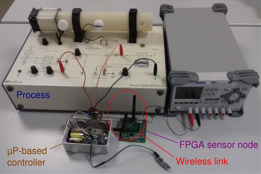
4 Experimental results
Figure 3 Experimental setup.
This section briefly presents an experiment aimed at evaluating the performance of our
design. Here, the FPGA-based device has been used as a wireless sensing unit to measure the
process output inside a closed-loop system. The controlled apparatus is a PT 326 thermal
process trainer, manufactured by Feedback; the apparatus is composed of a plastic tube
equipped with a blower and an electric heater on one of its ends and with a temperature
sensor on the opposite one. The objective is to control the temperature of the airflow in the
tube, as measured by the temperature sensor, acting on the heater’s power. The speed of the
blower can be changed too, to simulate different levels of external disturbances. Both the
input and output signals of the process trainer come in the form of voltage levels, allowing
for a straightforward connection to external sensing and control units.S. Seva, C. E. Lukaschewsky Mauriziano, W. Fornaciari, and A. Leva 4:9
In the setup, the FPGA-based sensor sends the measurements through a wireless connec-
tion to a wandstem board [21], which acts both as master node for the network and controller
for the closed-loop system.
IMC PID with λ = 0.1, disturbance response
44
y [◦ C]
42
40
80
60
u [%]
40
20
0 10 20 30 40 50 60 70 80 90 100
time [s]
Figure 4 Experimental results.
The presented experiment is a load disturbance rejection one, where a step-shaped increase
of the blower speed causes an non-measurable change in the airflow. The regulator used is
an IMC-PID one whose program, written in C++ language, runs on the master node. During
the experiments the process input and output and the number of samples sent have been
logged. The result is shown shown in figure 4, where from top to bottom, the plots show the
airflow temperature in ◦ C, the value of the control effort and the time distribution of the
packets sent over the wireless link, where a vertical bar is plotted whenever the regulator
received a sample from the sensing node.
The results obtained in this and other experiments show that the realised device can be
effectively used as the process’ output sensor in a closed-loop system, allowing to obtain
good performances while performing a quite low number of transmissions.
5 Conclusions and future work
We realised a low-power wireless sensor node suitable for real-time event-based control systems
without making use of microcontrollers of soft-cores, thereby showing that an approach based
completely on hardware components is feasible. This allows to significantly enhance both
the energy efficiency – especially if the design is converted into an ASIC – and the resilience
to malicious attacks.
As pointed out in the introduction, at present our design is effective only in a restricted
context, namely where control networks have a single-hop star topology. Future research
activity, then, will focus on overcoming these limitations.
Future developments will also be targeted towards enhancements in the aspects more
related to event-based control. Plans are to implement a bidirectional communication
between each node and the master one, for example to force the sending of measurements
or to interrupt data sending triggered by events, and support for triggering rules different
from the Send on Delta one will be added. We are also studying a timeout mechanism to
NG-RES 20204:10 A Low Energy FPGA Platform for Real-Time Event-Based Control
force the generation of an event after a given amount of time from the last one as a way to
ensure proper operation of the closed-loop system. The timeout can also be exploited as a
mechanism to periodically check the integrity of the communication channel.
References
1 K.E. Årzén. A simple event-based PID controller. In Proc. 14th IFAC World Congress,
volume 18, pages 423–428, Beijing, China, 1999.
2 K.J. Åström. Event Based Control. In A. Astolfi and L. Marconi, editors, Analysis and Design
of Nonlinear Control Systems, pages 127–147. Springer, Berlin, 2008.
3 K.J. Åström and B.M. Bernhardsson. Comparison of Riemann and Lebesgue sampling for
first order stochastic systems. In Proc. 41st IEEE Conference on Decision and Control, 2002,
volume 2, pages 2011–2016, Barcelona, Spain, 2002.
4 M. Beschi, A. Visioli, S. Dormido, and J. Sánchez. On the presence of equilibrium points in
PI control systems with send-on-delta sampling. In Proc. 50th IEEE Conference on Decision
and Control and European Control Conference CDC-ECC 2011, pages 7843–7848, Orlando,
FL, USA, 2011.
5 T. Blevins, D. Chen, S. Han, M. Nixon, and W. Wojsznis. Process Control over Real-Time
Wireless Sensor and Actuator Networks. In Proc. 17th IEEE International Conference on
High Performance Computing and Communication, 2015.
6 T. Blevins, M. Nixon, and W. Wojsznis. Event based control applied to wireless throttling
valves. In Proc. 1st International Conference on Event-based Control, Communication, and
Signal Processing, Krakow, Poland, 2015.
7 N. Cardoso de Castro, D. E. Quevedo, F. Garin, and C. Canudas de Wit. Energy-aware radio
chip management for wireless control. IEEE Transactions on Control Systems Technology,
25(6):2121–2134, 2017.
8 Y. Wei et Al. RT-wifi: Real-time high-speed communication protocol for wireless cyber-
physical control applications. In 2013 IEEE 34th Real-Time Systems Symposium, pages
140–149, Nashville, Tennessee, 2013.
9 G. Alderisi G. Patti and L. L. Bello. Introducing multi-level communication in the IEEE
802.15.4e protocol: The MultiChannel-LLDN. In Proceedings of the 2014 IEEE Emerging
Technology and Factory Automation (ETFA), pages 1–8, Barcelona, Spain, 2014.
10 J.W. Grizzle, C. Chevallereau, and C.L. Shih. HZD-based control of a five-link underactuated
3D bipedal robot. In Proc. 47th IEEE Conference on Decision and Control, pages 5206–5213,
Cancún, Mexico, 2008.
11 T. Henningsson and A. Cervin. A simple model for the interference between event-based
control loops using a shared medium. In Proc. 49th IEEE Conference on Decision and Control,
pages 3240–3245, Atlanta, GA, USA, 2010.
12 D. Henriksson and A. Cervin. Optimal on-line sampling period assignment for real-time
control tasks based on plant state information. In Proc. 44th IEEE Conference on Decision
and Control, pages 4469–4474, Seville, Spain, 2005.
13 B. Hensel, J. Ploennigs, V. Vasyutynskyy, and K. Kabitzsch. A simple PI controller tuning
rule for sensor energy efficiency with level-crossing sampling. In Proc. 9th IEEE International
Multi-Conference on Systems, Signals and Devices, pages 1–6, Chemnitz, Germany, 2012.
14 B. Hensel, V. Vasyutynskyy, J. Ploennigs, and K. Kabitzsch. An adaptive PI controller for
room temperature control with level-crossing sampling. In Proc. 2012 UKACC International
Conference on Control, pages 197–204, Cardiff, United Kingdom, 2012.
15 A. Leva, F. Terraneo, and S. Seva. Periodic event-based control with past measurements
transmission. In 2017 3rd International Conference on Event-Based Control, Communication
and Signal Processing (EBCCSP), pages 1–8, Madeira, Portugal, 2017.S. Seva, C. E. Lukaschewsky Mauriziano, W. Fornaciari, and A. Leva 4:11
16 Q. Liu, Z. Wang, X. He, and D. Zhou. A survey of event-based strategies on control and
estimation. Systems Science & Control Engineering: An Open Access Journal, 2(1):90–97,
2014.
17 S. Magnenat, P. Rétornaz, M. Bonani, V. Longchamp, and F. Mondada. ASEBA: A mod-
ular architecture for event-based control of complex robots. IEEE/ASME transactions on
mechatronics, 16(2):321–329, 2010.
18 M. Rabi and K.H. Johansson. Event-triggered strategies for industrial control over wireless
networks. In Proc. 4th Annual International Conference on Wireless Internet, pages 34:1–34:7,
Brussels, Belgium, 2008.
19 J. Sijs and M. Lazar. Event Based State Estimation With Time Synchronous Updates. IEEE
Transactions on Automatic Control, 57(10):2650–2655, 2012.
20 J. Song, A.K. Mok, D. Chen, M. Nixon, et al. Challenges of wireless control in process industry.
In Workshop on Research Directions for Security and Networking in Critical Real-Time and
Embedded Systems, 2006.
21 F. Terraneo, A. Leva, and W. Fornaciari. A High-Performance, Energy-Efficient Node for
a Wide Range of WSN Applications. In Proc. 2016 International Conference on Embedded
Wireless Systems and Networks, Graz, 2016.
22 F. Terraneo, L. Rinaldi, M. Maggio, A. V. Papadopoulos, and A. Leva. FLOPSYNC-2:
Efficient monotonic clock synchronisation. In 2014 IEEE Real-Time Systems Symposium,
pages 11–20, Rome, Italy, 2014.
23 F. Tramarin, A. K. Mok, and S. Han. Real-Time and Reliable Industrial Control Over
Wireless LANs: Algorithms, Protocols, and Future Directions. Proceedings of the IEEE,
107(6):1027–1052, 2019.
24 X.M. Zhang, Q.L. Han, and Bao-Lin B.L. Zhang. An overview and deep investigation
on sampled-data-based event-triggered control and filtering for networked systems. IEEE
Transactions on Industrial Informatics, 13(1):4–16, 2016.
NG-RES 2020You can also read