Developing an Optical Image-Based Method for Bridge Deformation Measurement Considering Camera Motion - MDPI
←
→
Page content transcription
If your browser does not render page correctly, please read the page content below
Article

Developing an Optical Image-Based Method for
Bridge Deformation Measurement Considering
Camera Motion
Vahid Abolhasannejad 1,*, Xiaoming Huang 1 and Nader Namazi 2
 1 School of Transportation, Southeast University, Nanjing 211189, China; huangxm@seu.edu.cn
 2 Department of Electrical Engineering and Computer Science, The Catholic University of America,
 Washington, DC 20064, USA; namazi@cua.edu
 * Correspondence: 230119738@seu.edu.cn or vahid.ahn@gmail.com

 Received: 26 June 2018; Accepted: 18 August 2018; Published: 21 August 2018

 Abstract: Since deformation estimation may lead to errors occurring when the camera vibrates, it is
 necessary to remove the image global motion before computing real bridge deformation. In this
 study, a combination of image motion correction algorithm and 2D image-based deformation
 measurement technique was utilized to address the issue of camera motion during the image data
 acquisition for bridge deformation measurement. Based on the proposed methodology, the image
 motion parameters were estimated by defining an effective sub-image in the image and using
 Iterative Affine Motion Estimator. Then the estimated parameters were applied to all pixels of each
 captured image to remove the motion effect. Finally, the corrected images were used to analyze by
 a 2D image-based deformation measurement technique in order to extract and measure real bridge
 deformation by tracking artificial or natural targets. The proposed methodology was validated by
 two experiments in the lab and field environments. Achieved results show the accuracy and
 reliability of the proposed methodology.

 Keywords: bridge deformation; motion correction; image-based technique

1. Introduction
 Deformation measurement is a key factor for safety and serviceability evaluation of bridge
structures during their service life [1]. To assure safe bridge performance, deformation must remain
within acceptable limits over the entire life of the structure. Therefore, it is crucial to accurately and
efficiently estimate and monitor the deformation amplitude of bridges in order to prevent
unpredictable collapse and deterioration. There are two major methodological categories for
deformation estimation of bridges; namely contact-based and non-contact-based.
 The contact-based measurement methods can be implemented through conventional
measurement devices including dial gauges, Linear Variable Differential Transformers (LVDTs),
and accelerometers [2–4]. Dial gauges and LVDTs are accurate devices for deformation
measurement, however, they need to be fixed, i.e., attached to the measurement point of the
structure. Additionally, using this method deformation can be measured in one direction only.
Accelerometers obtain the deformation through an indirect procedure that makes them less accurate
and more sensitive than other traditional instruments. These three devices also need voluminous
instruments that must be installed on the structure through a challenging and difficult procedure. As
a result, these instruments are at high risk for damage during the data gathering process.
 Non-contact-based measurement approaches use high technology instruments in order to
overcome the drawbacks of the conventional deformation sensors. Laser Doppler Vibrometer

Sensors 2018, 18, 2754; doi:10.3390/s18092754 www.mdpi.com/journal/sensors
Sensors 2018, 18, 2754 2 of 19

(LDV) [5,6], Global Positioning System (GPS) [7–12], laser scanning [13–15], and image-based
measurement methods [16–25] are among the most popular non-contact devices. However, all of
these methods suffer from drawbacks that limit their application for deformation measurement of
bridges. For example, despite the fact that LDV is a powerful technique for deformation
measurement, the high cost of this system prevents its wide application. In addition, the laser
intensity makes this method dangerous to use, especially over great distances. Reduced accuracy
and sampling rate are the limitations of GPS for bridge deformation measurement; however, its
precision can be affected by the number of existing satellites. As an optical remote sensing method,
the laser-scanning system is able to make the 3D cloud point of an object. This system does not need
any target or other kinds of surface preparation for measurement. In addition, since the data
capturing is a sequential procedure, this method is suitable for deformation measurement while the
static load is applied.
 Among all the aforementioned non-contact measurement methods, the image-based method
may be more applicable for the following reasons:
(1) Remote deformation measurement of bridges within the range of a few meters to hundreds of
 meters.
(2) Fully automated with performance in a real time manner.
 Non-contact image-based measurement methods have been widely used recently for
deformation measurement of road infrastructures, especially for bridge deformation measurements.
Based on the study conducted by Lee and Shinozuka [26] image processing methods were applied to
measure bridge dynamic deformation in real-time. In this study, a camcorder was used to capture
the image data. In addition, the displacement measurement results by the proposed method agreed
with those obtained through the laser vibrometer with small measurement noise. Digital image
correlation was utilized by Yoneyama [27] to measure bridge deformation. One of the limitations of
this method is the need to use the speckle pattern on the structure surface. Moreover, high quality
and expensive cameras are needed to obtain reliable results. Jiang et al. [28] presented a literature
review to describe the previously research works related to bridge deformation and structural
monitoring. In this research, the photogrammetric methods of bridge measurement have been
investigated since 1970s and the evolution of cameras, targets, network control, and software were
described. A close-range photogrammetric bridge deformation measurement system was developed
by Jiang and Jáuregui [29]. This system was applied to measure bridge deformation under static
loading conditions. Various kinds of camera configurations were installed and the methodology was
validated by experiments in the laboratory and field environments. In a study by Valença et al. [30],
deformation of a footbridge subjected to different loading situations was monitored. The results
showed that photogrammetry is advantageous comparing to traditional methods in structural
monitoring. In other research conducted by Riveiro et al., a low cost photogrammetric method was
utilized to measure the vertical bridge under-clearance [18]. Through this procedure, bridge
elements were reconstructed in a 3D space. The advantage of this method is to perform routine
bridge inspection, affording accurate and safe measurement. An image-based methodology was
developed by Ribeiro et al. [31] for the estimation of dynamic railway bridge deformation.
Equipment utilized consisted of high speed camera with a frame rate of 64 fps to 500 fps, camera
lens, targets, and lamps installed for measurement. Also, laser sensing technology was utilized for
bridge deformation measurement by Zhao et al. [32]. The results of that study showed the precision
of the proposed deformation measurement system. The vertical deformation of bridges was
measured in a real-time, non-contact, target-less manner by a research study in which the off-axis
digital image correlation method was utilized [33].
 The research presented thus far indicates that non-contact image-based techniques are superior
to other methods; however existing techniques do bear some limitations. As can be seen in most of
the image-based deformation measurement methods, a fixed-position camera was utilized to
measure the bridge deformation. In the field, camera motion due to ambient conditions such as wind
results in motion noise which affects measurements, leading to significant error in the deformation
measurements. In some field measurement cases, it was suggested that the probable camera
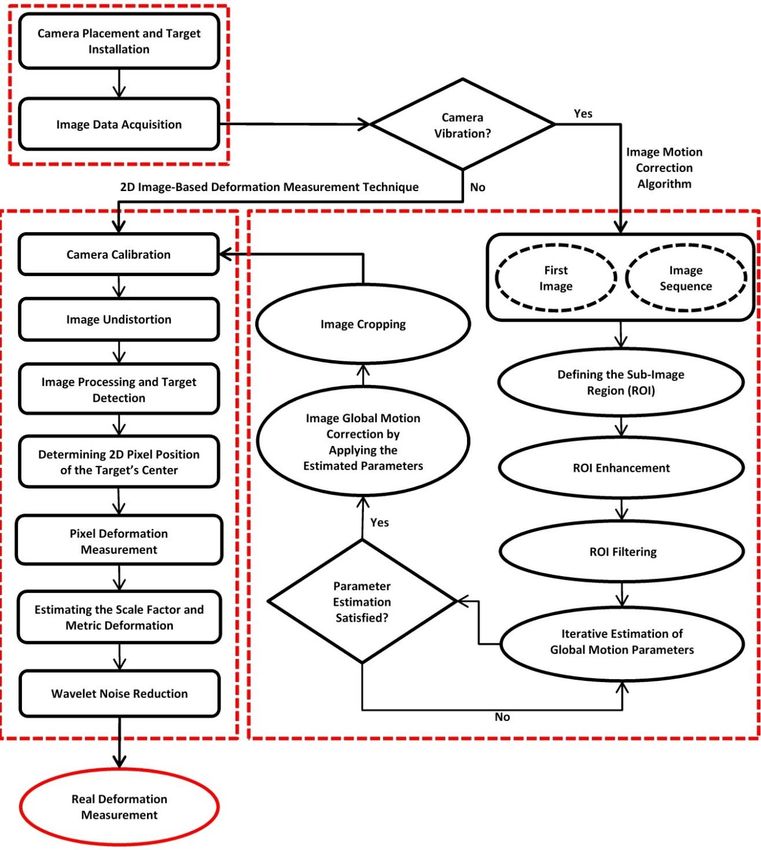
Sensors 2018, 18, 2754 3 of 19

movement may be somewhat decreased by installing windshield equipment on the camera at the
bridge site [26].
 It is also noted that some authors have reported the use of reference points for estimating
camera motion relative to a movable camera. For example, Olaszek [34] developed an optical
image-based method in which a reference system was defined through one separate target and
camera channel in order to estimate the probable movement of the camera and correct results
obtained by the vibrated camera in the real field bridge deformation measurement. However, using
this reference point requires additional equipment such as camera and targets. Moreover, using a
reference-point system limits the number of monitored points which depends on the number of
cameras and targets utilized. Consequently, the use of a reference-point is limited in scope and does
not efficiently address the issues associated with ambient camera motion. Wagner et al. [35] also
proposed a bridge monitoring method using a video-tacheometer or Image Assisted Total Station
(IATS) to determine the absolute bridge displacement. Through this system, photogrammetric
image measurement methods are utilized to detect the target points and total station methods such
as precise angle and distance measurement (to prisms or reflectorless) are employed to control the
stability of the monitoring station. In another study conducted in 2015 [36], the usage of IATS was
investigated to monitor the vibration and displacement of civil engineering structures. In this study,
the possible rotations of the camera (due to rotations of telescope or tilts of the IATS) were corrected
by using total station to achieve the accurate displacement values. In this case, additional sensors
and data acquisition system are required to estimate the possible movement of camera. Data fusion
techniques should also be adopted to integrate different data sources. These limitations, along with
the low camera frame rate make a challenging and costly procedure for measurement of bridge
deformation. Considering these facts, it is necessary to develop a methodology which is able to
address the issue of camera motion before extracting the real deformation of bridge structure, one
which is convenient, time-saving and cost effective.
 As such, the current study is devoted to the development, implementation and presentation of
a non-contact image-based method for the measurement of bridge deformation considering camera
motion. The proposed method deals with ambient camera motion without requiring any additional
optical equipment or extra time and cost for arranging the measurement procedure. By the proposed
method, the image global motion caused by the camera motion is estimated and the image is
corrected before calculation of real bridge deformation. Therefore, first the image motion correction
method is presented. Then the 2D image-based deformation measurement method is utilized to
measure the real bridge deformation by tracking artificial or natural targets. Thirdly, the proposed
methodology is validated through asphalt Uniaxial Compression (UC) test in the lab and finally the
validated methodology is tested and verified on a real bridge in the field.
 In the remainder of this work, the principles of the algorithm for image motion correction as
well as the 2D image-based deformation measurement technique are described. Then, the
experimental study in the lab and the field is conducted to verify the proposed methodology.
Finally, the future research challenges are presented.

2. Methodology of Deformation Measurement
 In this section, the methodology of deformation measurement under described conditions is
presented. The proposed approach addresses two main challenges, camera motion due to ambient
conditions such as wind in the field environment as well as accurate measurement of bridge
deformation through a non-contact image-based method. The proposed methodology is a
combination of image global motion correction algorithm and 2D image-based deformation
measurement technique. This combination is generally called “2D image-based motion correction
methodology” in this paper. Figure 1 illustrates the schematic diagram of 2D image-based motion
correction methodology. In the following, each part of the methodology is described.
Sensors 2018, 18, 2754 4 of 19

 Figure 1. Schematic diagram of 2D image-based motion correction methodology.

2.1. Image Global Motion Correction Algorithm
 In this section, an effective technique for the correction of the image global motion is described.
Several research works have been conducted for image global motion estimation and correction [37–41].
Generally, there are two types of pixel motion in an image, namely global and local motion. Global
motion includes the translation and/or rotation of the image due to camera motion. Local motion
generally is due to the object’s movement within the image area, such as real bridge deformation. In
order to measure accurate local motion, one should separate local motion from the image global
motion which occurs as a result of camera motion. First a square sub-image, including the fixed
natural distinctive features but not including the parts with local motion, is considered as the
reference region of interest (ROI) in the image sequence for the estimation of image global motion
parameters. This square sub-image is defined and selected from within the image so that it is only
globally affected by motion and distinctive fixed elements exist within the defined region. In this
study, the size of ROI is considered equal to 256 × 256 pixels. It should be noted that the natural
Sensors 2018, 18, 2754 5 of 19

background features (within the ROI) are assumed to be stationary. These features may be natural
such as buildings, rocks, trees, etc. or artificial. The image motion correction procedure is started by
applying image enhancement and filtering on the ROI using the Adaptive Wiener Filter (AWF) and
blurring filter [42]. Then, in order to estimate and correct the image global motion, the Iterative
Affine Motion Estimator (IAME) is utilized. Refer to Namazi et al. [39] provides an informative
explanation of the concept of IAME. Through this algorithm, the ROI intensity equations in two
successive images are:

 H1 (x) = I(x) + n1 (x) (1)

 H2 (x) = I (x − Pg (x)) + n2 (x); x ∈ Γg (2)

where x = (x1 , x2 )T is the vector of pixel coordinate, I(x) is the noise-free intensity of the previous
ROI, H1 (x) is the noisy intensity of the previous ROI and n1 (x) represents noise, Pg (x) specifies the
global motion vector at the location x, and n2 (x) denotes noise. In addition, the region Γg is the
respective partition of H2 (x) corresponding to globally displaced pixels [39].
 In this algorithm, the first image is considered as the reference image and the image sequence
are continuously (frame by frame) analyzed to estimate the global motion parameters and remove
the effect of camera motion. So, by following the IAME algorithm, the image global motion
parameters, including translation, rotation, expansion, zooming, skewing and scaling are estimated.
It means that the proposed image motion correction algorithm is capable of estimating and
removing the camera translation and rotation in different camera axes. The final estimated global
motion parameters obtained through analysis of ROI are then applied on the all image pixels;
subsequently each image is corrected considering the image global motion.
 With all the captured images globally corrected, they were cropped from a fixed reference point
at the bottom left of each image, thus preparing all the images for deformation measurement
analysis. This fixed reference point could be selected by determining a crop point from among the
existing elements in the image.

2.2. 2D Image-Based Deformation Measurement Technique
 After all the obtained image data were globally corrected, the 2D image-based deformation
measurement technique was applied to calculate the real bridge deformation. The proposed
image-based technique is a non-contact target-based method which is described below.
 First the intrinsic and extrinsic camera parameters are calculated through MATLAB Camera
Calibration Toolbox [43]. These parameters can be shown as the following Equation [44]:
 αu s u0
 K=[0 αv v0 ] (3)
 0 0 1
where αu and αv are the scale factor along the u and v coordinate axes, respectively; c indicates
the image coordinates of the principal point, [u0 , v0 ]T ; and s is the skew.
 In the next stage, the distorted image is converted into an undistorted image by applying the
camera calibration results [45]. With the radial and tangential distortion functions known, and using
the following equations, the distorted coordinates are calculated.
 Then an image processing and analysis algorithm is utilized to detect the target points
including artificial or natural targets and estimate the center position of targets. It should be noted
that in some situations, access to the monitored bridge and installation of artificial targets is difficult.
So, the natural targets are installed and tracked through the image processing and analysis
algorithm to reduce the required cost and time of bridge deformation measurement. The detailed
flowchart of image processing and analysis algorithm is shown in Figure 2.
Sensors 2018, 18, 2754 6 of 19

 Figure 2. Flowchart of the image processing and analysis algorithm.

 As shown in Figure 2, the undistorted image as the input image is being processed through an
image processing algorithm. First the canny edge detection algorithm is applied to detect the objects
boundaries [46]. Then the effective area around the target is defined by using the filtering algorithm.
The mentioned target can be artificial (for example, circular) or natural feature which is located
within the defined effective area or region of interest (ROI). In the next stage, by filling the holes in
the image and removing noises, the target is detected [47]. Finally, the 2D center position of each
target is determined by the image analysis algorithm of region descriptor [48].
 Accordingly, all the successive images are considered to be analyzed for estimation of
momentary metric position of target center at time . Having the center pixel position of each target
in the captured image at time ( + 1) and ( ) that correspond to (x +1 , y +1 ) and (x , y ) and the
image scale factor (p) , the metric position of each target center is calculated through the
following equation:

 Y +1 = Y + p(y +1 − y ) (4)
where Y is the metric vertical position of each target center at time ( ) and Y +1 is the metric
vertical position of each target center at time ( + 1). The initial value of Y is considered equal to
zero. The image scale factor can be calculated by comparing the object dimension in the real field
and in the image [49].
 Finally, the wavelet transform is utilized to reduce the unexpected noise or variations of the
obtained results [50]. By applying this de-noising procedure, more smooth results will be achieved.

3. Experimental Study
 In this section, the proposed 2D image-based motion correction methodology is tested in both
lab and field environments to verify the capability of this method for addressing the issue of camera
motion during image data gathering. First, asphalt Uniaxial Compression (UC) test is performed in
the lab to validate the proposed methodology. In this experiment, a cylindrical asphalt specimen is
loaded by the Universal Testing Machine (UTM) and deformation is measured and computed by
both traditional and 2D image-based motion correction methods. Then the proposed methodology is
applied on the real bridge in the field environment to show the reliability of the proposed
methodology.
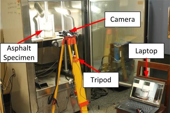
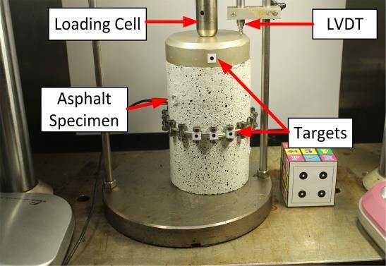
Sensors 2018, 18, 2754 7 of 19

3.1. Lab Experiment

3.1.1. Test Specifications and Data Preparation
 In order to validate the proposed methodology in the laboratory, a test was performed on the
asphalt specimen. This Uniaxial Compression (UC) test had been carried out by Sun et al. in 2016 [23]. In
this test, vertical deformation occurs by applying the compressive force on the cylindrical sample.
This deformation was measured through 2D image-based motion correction methodology and
validated by using conventional methods including LVDT. First, we briefly present the
configuration and specifications of the UC test as shown in Figure 3.

 (a) (b)
 Figure 3. Test configuration: (a) test set up; (b) asphalt specimen.

 In this experiment, a cylindrical asphalt specimen with a height of 15 cm and a diameter of 10
cm was loaded under the variable vertical load, which resulted in vertical deformation in the
specimen during the time of loading. This actual deformation of the specimen was measured using
the LVDT installed at the top of the specimen. The time and applied load were also measured by the
Universal Testing Machine (UTM) during the test. In addition, to estimate the vertical deformation
through the 2D image-based motion correction methodology, four circular black targets with a 4 mm
diameter (G1 , G2 , G3 , G4 ) were used and installed at specific points on the surface of the asphalt
specimen as shown in Figure 4b. That made it possible to estimate the deformations at these target
points using image data processing and analysis algorithm. The camera used in this test was a
webcam (Logitech C270 HD, Suzhou, China) with a resolution of 1280 × 960 pixels and a maximum
frame rate of 30 fps.
 The test image data and the real data from LVDT were gathered during the loading operation.
The calibration image data was also collected before starting the main test. Also all image data
captured by the camera is transferred to and stored on a hard drive.
 However, in the research work conducted by Sun et al. [23], it was assumed that the camera was
fixed and remained motionless throughout the entire test. In this situation, the vertical deformation
of asphalt specimen will be estimated directly by 2D image-based deformation measurement
technique. But, in the present study, the researchers aim to calculate vertical deformation taking into
consideration camera motion. Therefore, in order to take into account the effect of camera motion
during the image data collection, the images of asphalt specimen which were captured through a
fixed camera were synthetically translated (along X and Y axis of image) and rotated (about the
normal axis of image plane) up to a few pixels and degrees in each frame through a random
procedure to simulate the real camera motion. Figure 4 shows the main captured image of asphalt
specimen which was considered for testing the 2D image-based motion correction methodology. As
can be seen, the original image as well as the synthetically moved image is shown in this figure.
Sensors 2018, 18, 2754 8 of 19

 (a) (b)
 Figure 4. Image data preparation: (a) main captured image; (b) synthetically moved image.

3.1.2. Image Data Analysis
 Three types of image data were generated: original image data obtained through fixed camera
(Group 1), image data generated by synthetically image translation and rotation or before applying
the image motion correction algorithm (Group 2), and corrected image data after applying the image
motion correction algorithm (Group 3).
 As for the data in the first group, it is possible to directly use the 2D image-based deformation
measurement technique to calculate the asphalt vertical deformation. So, firstly, the original
captured image data were undistorted considering the camera calibration parameters as mentioned
in Table 1.

 Table 1. Camera calibration parameters.

 Parameter Value
 Camera Focal Length 1428
 Skew γ=0
 u0 = 604.66
 Camera Principle Point
 v0 = 520.04
 k1 = −0.034
 Radial Lens Distortion
 k2 = 0.053

 Then the images were processed and analyzed in order to detect the target and determine the
pixel position of each target center during the time. The circular target detected by applying the
image processing and analysis algorithm is shown in Figure 5.

 Figure 5. Target detection and positioning.

 Having the pixel locations of the target center in each image sequence, as well as the image scale
factor, the asphalt vertical deformations were computed. Subsequently the metric positions of each
Sensors 2018, 18, 2754 9 of 19

target center during the time were estimated using Equation (4). It should be noted that in this
experiment, it is assumed that the diameter of a circular target is considered as the known physical
length on the asphalt surface in order to estimate the scale factor. Finally, the wavelet transform was
used to reduce the existing noise of the results.
 For the analysis of the image data in Group 2, the same method as the first group was applied to
calculate the asphalt vertical deformation. Since the images were translated and rotated in this state;
thus the achieved deformation results were not be going to be reliable. If the camera vibrated due to
ambient conditions, direct use of the 2D image-based deformation measurement technique would
not be effective to achieve reliable results. Therefore, in order to solve the problem, first it is
necessary to correct the image data through the image global motion correction algorithm as
described in the previous section and then apply the 2D image-based deformation measurement
technique to estimate the vertical deformation.
 As such, the image motion correction parameters were first estimated by taking into account a
sub-image called ROI of the main image. Subsequently the obtained parameters were applied on all
pixels of the entire image, as shown in Figure 6a,b. In this way, the images were corrected with
occurred movements removed. Finally, the corrected images were cropped by selecting a natural
point located at the bottom left side of the image (Figure 6c). As such, the corrected images (Group 3)
were generated. Therefore, these images were considered as the final output for applying the 2D
image-based deformation measurement technique as described above.

 (a) (b)

 (c)
 Figure 6. Image motion correction procedure: (a) ROI definition on a synthetically moved image;
 (b) image correction and determining a crop point; (c) Cropped corrected image as the final output image.

 Finally, by applying the proposed methodology, three categories of results are achieved from
three groups of images, including original images, synthetically moved images (before image
motion correction) and corrected images (after image motion correction). Then, by comparing the
achieved deformation results from analysis of all image data groups to each other and with those
obtained through LVDT, the proposed methodology, including the image global motion correction
algorithm and the 2D image-based deformation measurement technique were validated. It should
Sensors 2018, 18, 2754 10 of 19

be noted that the deformation results of LVDT are only available at the location of target G1 . As can
be seen in Figure 7, since target G1 can not be detected and analyzed in the image, a natural point at
the top of the asphalt specimen near target G1 was considered to have been tracked. Detecting and
tracking the natural target is performed by using the proposed image processing and analysis
algorithm. It should be noted that all the stages of the proposed 2D image-based motion correction
methodology including the image motion correction algorithm and 2D image-based deformation
measurement technique is accomplished through MATLAB software.

 Figure 7. Natural point instead of target G1 .

3.1.3. Comparison of Results and Methodology Validation
 Based on the proposed methodology, the image data (Groups 1, 2 and 3) were analyzed and the
comparison was accomplished by comparing the deformation results of asphalt specimen through
analysis of the three groups of image data previously described. First, these results are compared at
target G1 or natural point, which is located at the top of the asphalt specimen. The comparison of
deformation results versus the time are illustrated in Figure 8.

 (a) (b)

 (c)
 Figure 8. Comparison of deformation results at target G1 (or natural point) by analysis of three
 image data groups.
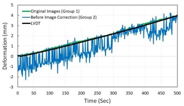
Sensors 2018, 18, 2754 11 of 19

 In Figure 8 above, the deformation results were compared considering three different states:
(a) deformation measurement using Group 2, Group 3, and LVDT,
(b) deformation measurement using Group 1, Group 2, and Group 3,
(c) deformation measurement using Group 1, Group 2, and LVDT.
 The comparison results showed that the deformation results obtained from the analysis of
corrected images (after image motion correction) agree with those obtained from the analysis of
original images or LVDT as the ground-truth value (Figure 8a,b). This could demonstrate the
reliability of the proposed methodology, including the image motion correction algorithm and 2D
image-based deformation measurement technique. In addition, the accuracy of 2D image-based
deformation measurement technique was approved by comparing the results of the original images
analysis and LVDT (Figure 8c). For better comparison, two measures of root mean square error
(RMSE) and normalized root mean square error (NRMSE) were used to quantify the accuracy of
both the image motion correction algorithm and the 2D image-based deformation measurement
technique. These measures are defined in the following:

 n
 1
 RMSE = √ ∑(E − O )2 (5)
 n
 =1

 RMSE √1 ∑n =1(E − O )2
 n (6)
 NRMSE = = × 100
 Omax − Omin Omax − Omin
where n is the number of measurement data; E is the estimated deformation at time (as
measured by 2D image-based deformation measurement technique); O is the true deformation
value at time (as measured by LVDT); and Omax = max (O ), Omin = min (O ).
 The existing errors were calculated and summarized in Table 2 based on Equations (5) and (6)
above. As can be seen in Table 2, the low measurement error (4.57%) shows the accuracy of the
proposed methodology. In addition, the obtained results showed that the natural target can be
effectively and accurately used instead of artificial target for deformation measurement.

 Table 2. Deformation measurement error

 Comparison State RMSE (mm) NRMSE (%)
 (a) Group 3-LVDT 0.12 3.06
 (b) Group 1–Group 3 0.18 4.57
 (c) Group 1-LVDT 0.91 2.31

 After validating the proposed methodology by deformation measurement analysis at target G1
(or natural point), the results comparison was done by applying the proposed methodology at the
remaining targets of G2 , G3 , and G4 . This comparison includes comparing the deformation results
obtained from the analysis of image data Groups 1, 2, and 3 which corresponds to original images,
synthetically moved images (before image motion correction), and corrected images (after image
motion correction), respectively. The results are shown in Figure 9.
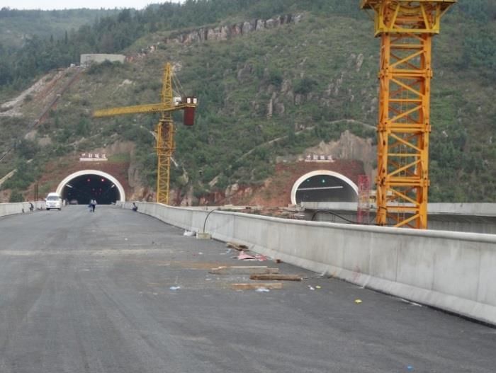
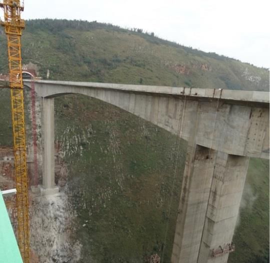
Sensors 2018, 18, 2754 12 of 19

 (a) (b)

 (c)
 Figure 9. Comparison of deformation results: (a) at Target G2 ; (b) at Target G3 ; (c) at Target G4 .

 According to Figure 9, the trend of deformation results obtained by the analysis of image Group 2
shows no agreement with those obtained through the analysis of original images (image Group 1).
Thus, by applying the image motion correction algorithm and correcting the images in Group 2, then
analyzing the corrected images (Group 3), accurate deformation results are obtained (according to
the Group 3 graph). More analysis was done to quantify the existing measurement error as shown in
Table 3. Based on measurement errors, it can be concluded that the proposed methodology is of
acceptable accuracy.
 After verification of the proposed methodology in the lab, the real bridge experiment in the
field environment under the vibration condition was conducted in order to measure the dynamic
deformation of bridge.

 Table 3. Deformation measurement error

 Comparison State RMSE (mm) NRMSE (%)
 Target G2 (Group 1–Group 3) 0.138 5.79
 Target G3 (Group 1–Group 3) 0.187 7.52
 Target G4 (Group 1–Group 3) 0.239 9.79

3.2. Bridge Experiment

3.2.1. Test Configuration and Data Analysis
 In this section, a real bridge experiment in the field environment was conducted to investigate
the reliability and efficiency of the proposed methodology. The test was performed at a new
highway concrete bridge located in a mountainous area in Yunnan Province, China, with a total
length of 336 m. It has three spans including one middle (length: 160 m) and two lateral spans
(length: 88 m). Two separate parallel congruent unidirectional bridges span the valley to manage
traffic flow coming from the opposing mountain. The bridge structure and its specifications are
shown in Figure 10.
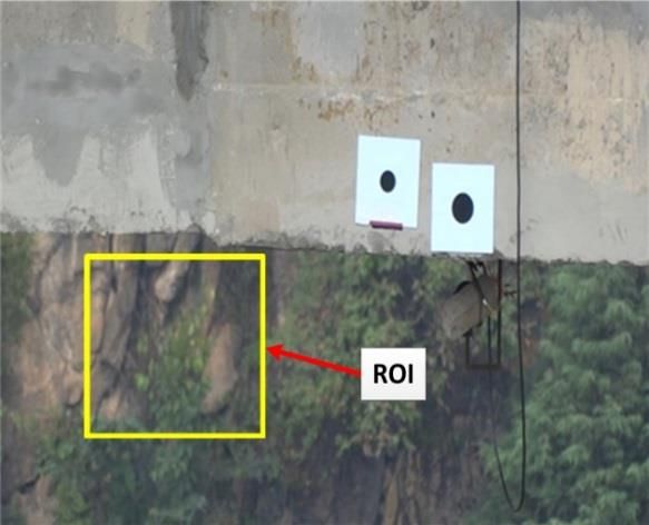
Sensors 2018, 18, 2754 13 of 19

 As can be seen in Figure 10, the two parallel bridges are too high and the deformation
measurement point is located at the middle point of the bridge. Considering the mentioned
condition, the circular target (with diameter of 70 mm) was installed on the lateral surface of the first
bridge and at the middle span and middle point. The camera (Sony DSC-HX300, Shenzhen,
Guangdong, China) with the image resolution of 1440 × 1080 pixels and frame rate of 30 fps) was also
placed on the second bridge (Figure 11). As such, the image data acquisition system was ready for
image data gathering under dynamic load.
 Since the camera was placed on the bridge deck, some ambient conditions such as bridge
vibration caused by traffic flow or wind may affect the fixed position of the camera and
subsequently, the camera may vibrate or move during image data gathering.

 (a) (b)

 (c)
 Figure 10. Bridge specifications (Measurement unit: m): (a) bridge structure; (b) bridge deck;
 (c) bridge dimensions.
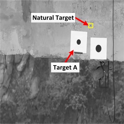
Sensors 2018, 18, 2754 14 of 19

 Figure 11. Configuration of image-based deformation measurement system.

 For bridge loading, a heavy cargo truck was passed over the bridge to apply the standard
dynamic load. At the same time, the image data gathering was also performed during the bridge
loading. Since the camera vibrated during the image collection procedure, the captured images were
subjected to motion. In this case, the proposed 2D image-based motion correction methodology
which was previously developed and verified was utilized to estimate and measure bridge vertical
dynamic deformation considering image global motion.
 Therefore, the global motion of images was corrected using the image global motion correction
algorithm described. The affine motion estimator was applied to the defined ROI in order to
estimate the motion correction parameters. Subsequently, the whole image was corrected by
applying these parameters to all pixels of the image as shown in Figure 12a. Then, the 2D
image-based deformation measurement technique was utilized to estimate the bridge vertical
dynamic deformation by tracking the circular target point A (see Figure 12b) in successive images.

 (a) (b)
 Figure 12. Image global motion correction: (a) specifying ROI for motion parameter estimation;
 (b) generated corrected image.

 In addition, a natural point near target A was defined to be detected and tracked as shown in
Figure 12b to investigate the reliability of the proposed methodology. As can be seen in Figure 12b,
an ROI was defined around the natural point and then the proposed 2D image-based deformation
measurement technique was applied to track the natural target and measure the vertical
deformation of bridge by analyzing the image data before and after image motion correction.
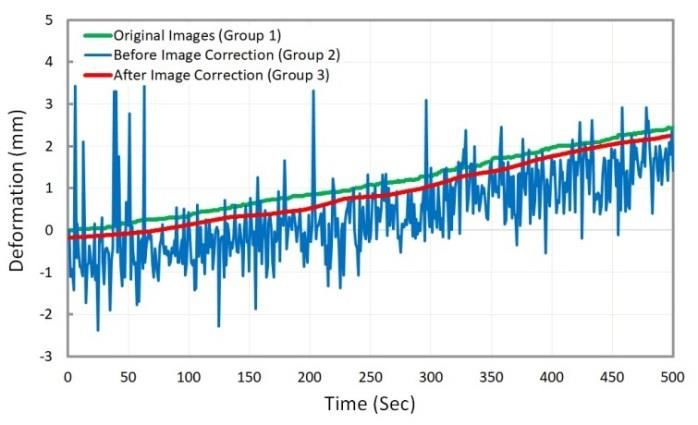
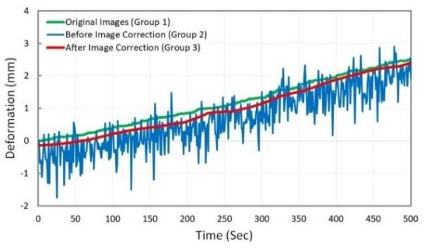
Sensors 2018, 18, 2754 15 of 19

3.2.2. Results and Discussion
 The captured images were corrected by analyzing the images obtained through the vibrated
camera. Subsequently, the bridge deformation was calculated under dynamic load. In this
experiment, two groups of images, those before and those after image global motion correction were
analyzed. Figure 13 compares the results of bridge dynamic vertical deformation for each scenario at
both target A and defined natural target. Comparison of the deformation results obtained by analysis
of these two groups of image data enabled verification of the efficiency of the proposed methodology.
 As indicated in Figure 13, the image global motion which occurred due to the camera motion
during the data gathering was corrected, and finally the real bridge deformation was extracted.
Based on the time-deformation diagrams in Figure 13, the obtained deformation results through
analyzing and tracking circular target A and defined natural target showed the reliability of the
proposed methodology.

 (a)

 (b)
 Figure 13. Comparison of bridge deformation measurement results before and after image motion
 correction: (a) at target A; (b) at natural target.

 Considering the experiments conducted in this study, it was proven that the real deformation of
a bridge can be accurately calculated in the presence of camera motion. Compared to previous
researches regarding bridge deformation measurement, it was found that the proposed
methodology is a convenient, efficient and cost effective method for estimating bridge deformation
in the presence of camera motion. The proposed methodology can be utilized as a primary step for
addressing the problem of deformation measurement considering the camera motion.
 While reliable results were achieved by the proposed method, some research issues can be
investigated in the future which are explained in the following:
- According to the proposed method in this study, fixed background features are required to be
 defined for estimation of camera motion parameters. But finding stationary background
 features is challenging in some situations, for example on the shoreline. So, this challenge can be
 addressed by using inertial measurement unit (IMU) sensors in the Unmanned Aerial Vehicle
 (UAV) for camera motion estimation that can be investigated in the future.
Sensors 2018, 18, 2754 16 of 19

- Different issues may affect the accuracy of bridge deformation measurement including: the
 distance between camera and bridge, using various types of cameras, and using different
 lenses. These issues can also be considered as the future researches.
- In this study, 2D image-based deformation measurement technique was developed to measure
 the in-plane vertical bridge deformation in presence of camera motion as described in Section 2.
 However, large out-of-plane deformation occurs in some of structures. For this case, the usage
 of multiple cameras such as stereo vision system would be an option to be investigated in
 the future.

4. Conclusions
 The camera motion due to ambient conditions such as wind is a problem for accurate bridge
deformation measurement, especially in the field environment. It is necessary, therefore, to find and
develop an efficient image-based methodology to use the moved images as input and compute the
real bridge deformation accurately and conveniently. This paper focused on the development and
implementation of an image-based technique by which the issue of camera motion is addressed in
less time with less cost. In addition, a combination of image motion correction algorithm and 2D
image-based deformation measurement technique was developed to measure and extract real bridge
deformation from the vibrated images in a continuous and convenient manner. Finally, two
experiments were conducted (one in the lab and the other in the field) to test and verify the proposed
methodology. The obtained images were categorized in different groups (original images, before
image motion correction and after image motion correction), analyzed based on the proposed
methodology through MATLAB. Then the real deformation was estimated for each image data
group and compared. In addition, the validity of the proposed methodology was investigated by
detecting and tracking artificial and natural targets.
 Comparing the deformation results obtained through analysis of image data before and after
motion correction with those obtained through original images and LVDT verified the accuracy and
efficiency of the proposed methodology. This methodology can be considered a suitable method for
addressing the issue of camera motion.
 Given the challenges addressed in this study through the proposed methodology including
detection of fixed natural background features within the image to calculate camera motion
parameters, removing camera motion (translation and rotation) by developed image motion
correction algorithm, estimating the bridge displacement using one camera and 2D image-based
deformation measurement technique, and measuring the vertical in-plane deformation of bridge
structure, a monitoring base was made toward measuring the bridge deformation in presence of
camera motion. In addition, the challenges which can be investigated in the future were presented,
including the usage of UAV for measuring bridge displacement, adopting IMU sensors to estimate
camera motion, and using multiple cameras for measuring out-of-plane motion of the structure.
Considering the contributions of this study regarding the bridge deformation measurement in
presence of camera motion, and the described possible future studies, it is expected that the
capabilities of the proposed methodology can be extended and improved in the near future.

Author Contributions: Conceptualization, V.A. and N.N.; Data curation, V.A.; Formal analysis, V.A. and N.N.;
Funding acquisition, X.H.; Investigation, V.A.; Methodology, V.A. and N.N.; Project administration, X.H.;
Resources, X.H.; Software, V.A. and N.N.; Supervision, X.H.; Validation, V.A. and N.N.; Visualization, V.A.;
Writing—original draft, V.A.; Writing—review & editing, V.A., X.H. and N.N.

Funding: This research was funded by China Scholarship Council (Award No. 2011DFH997).

Conflicts of Interest: The authors declare no conflict of interest.

References
1. Qi, X.; Lichti, D.; El-Badry, M.; Chow, J.; Ang, K. Vertical Dynamic Deflection Measurement in Concrete
 Beams with the Microsoft Kinect. Sensors 2014, 14, 3293–3307.
Sensors 2018, 18, 2754 17 of 19

2. Paultre, P.; Proulx, J.; Talbot, M. Dynamic testing procedures for highway bridges using traffic loads.
 J. Struct. Eng. 1995, 121, 362–376.
3. Park, K.T.; Kim, S.H.; Park, H.S.; Lee, K.W. The determination of bridge displacement using measured
 acceleration. Eng. Struct. 2005, 27, 371–378.
4. Park, J.W.; Sim, S.H.; Jung, H.J. Development of a wireless displacement measurement system using
 acceleration responses. Sensors 2013, 13, 8377–8392.
5. Nassif, H.H.; Gindy, M.; Davis, J. Comparison of laser Doppler vibrometer with contact sensors for
 monitoring bridge deflection and vibration. NDT E Int. 2005. 38, 213–218.
6. Helmi, K.; Taylor, T.; Zarafshan, A.; Ansari, F. Reference free method for real time monitoring of bridge
 deflections. Eng. Struct. 2015, 103, 116–124.
7. Meng, X.; Roberts, G.W.; Cosser, E.; Dodson, A.H.; Barnes, J.; Rizos, C. Real-time bridge deflection and
 vibration monitoring using an integrated GPS/Accelerometer/Pseudolite System. In Proceedings of 11th
 International Symposium on Deformation Measurements, Santorini, Greece, 25–28 May 2003; Volume 6,
 pp. 25–28.
8. Meng, X.; Dodson, A.H.; Roberts, G.W. Detecting bridge dynamics with GPS and triaxial accelerometers.
 Eng. Struct. 2007, 29, 3178–3184.
9. Moschas, F.; Stiros, S. Measurement of the dynamic displacements and of the modal frequencies of a
 short-span pedestrian bridge using GPS and an accelerometer. Eng. Struct. 2011, 33, 10–17.
10. Handayani, H.H.; Taufik, M. Preliminary study of bridge deformation monitoring using GPS and CRP
 (case study: Suramadu Bridge). Procedia Environ. Sci. 2015, 24, 266–276.
11. Han, H.; Wang, J.; Meng, X.; Liu, H. Analysis of the dynamic response of a long span bridge using
 GPS/accelerometer/anemometer under typhoon loading. Eng. Struct. 2016, 122, 238–250.
12. Lee, J.K.; Lee, J.O.; Kim, J.O. New Quality Control Algorithm Based on GNSS Sensing Data for a Bridge
 Health Monitoring System. Sensors 2016, 16, 774.
13. Fuchs, P.A.; Washer, G.A.; Chase, S.B.; Moore, M. Laser-based instrumentation for bridge load testing.
 J. Perform. Constr. Facil. 2004, 18, 213–219.
14. Park, H.S.; Lee, H.M.; Adeli, H.; Lee, I. A new approach for health monitoring of structures: Terrestrial
 laser scanning. Comput. Aided Civ. Infrastruct. Eng. 2007, 22, 19–30.
15. Gordon, S.J.; Lichti, D.D. Modeling terrestrial laser scanner data for precise structural deformation
 measurement. J. Surv. Eng. 2007, 133, 72–80.
16. Wang, T.T.; Jaw, J.J.; Chang, Y.H.; Jeng, F.S. Application and validation of profile–image method for
 measuring deformation of tunnel wall. Tunn. Undergr. Space Technol. 2009, 24, 136–147.
17. Detchev, I.; Habib, A.; El-Badry, M. Image-based deformation monitoring of statically and dynamically
 loaded beams. In Proceedings of the International Achieves of the Photogrammetry, Remote Sensing and
 Spatial Information Sciences, Melbourne, Australia, 25 August–1 September 2012.
18. Riveiro, B.; Jauregui, D.V.; Arias, P.; Armesto, J.; Jiang, R. An innovative method for remote measurement
 of minimum vertical underclearance in routine bridge inspection. Autom. Constr. 2012, 25, 34–40.
19. Tian, Y.-Q.; Zhang, L.; Guo, M.; Shan, L.-y. Investigation of the deformation properties of asphalt
 mixtures with DIC technique. Constr. Build. Mater. 2012, 37, 581–590.
20. Salvini, R.; Francioni, M.; Riccucci, S.; Bonciani, F.; Callegari, I. Photogrammetry and laser scanning for
 analyzing slope stability and rock fall runout along the Domodossola–Iselle railway, the Italian Alps.
 Geomorphology 2013, 185, 110–122.
21. Scaioni, M.; Barazzetti, L.; Giussani, A.; Previtali, M.; Roncoroni, F.; Alba, M.I. Photogrammetric
 techniques for monitoring tunnel deformation. Earth Sci. Inform. 2014, 7, 83–95.
22. Che, A.; Tang, Z.; Feng, S. An elastic-wave-based full-wave field imaging method for investigating
 defects in a high-speed railway under-track structure. Soil Dyn. Earthq. Eng. 2015, 77, 299–308.
23. Sun, L.; Abolhasannejad, V.; Gao, L.; Li, Y. Non-contact optical sensing of asphalt mixture deformation
 using 3D stereo vision. Measurement 2016, 85, 100–117.
24. Whiteman, T.; Lichti, D.; Chandler, I. Measurement of deflections in concrete beams by close-range
 photogrammetry. In Proceedings of the Symposium on Geospatial Theory, Processing and Applications,
 Ottawa, ON, Canada, 8–12 July 2002.
25. Fraser, C.; Riedel, B. Monitoring the thermal deformation of steel beams via vision metrology.
 J. Photogramm. Remote Sens. 2000, 55, 268–276.
Sensors 2018, 18, 2754 18 of 19

26. Lee, J.J.; Shinozuka, M. A vision-based system for remote sensing of bridge displacement. NDT E Int.
 2006, 39, 425–431.
27. Yoneyama, S.; Kitagawa, A.; Iwata, S.; Tani, K.; Kikuta, H. Bridge deflection measurement using digital
 image correlation. Exp. Tech. 2007, 31, 34–40.
28. Jiang, R.; Jáuregui, D.; White, K. Close-range photogrammetry applications in bridge measurement:
 Literature review. Measurement 2008, 41, 823–834.
29. Jiang, R.; Jauregui, D.V. Development of a digital close-range photogrammetric bridge deflection
 measurement system. Measurement 2010, 43, 1431–1438.
30. Valença, J.; Júlio, E.; Araújo, H. Applications of photogrammetry to structural assessment. Exp. Tech. 2012,
 36, 71–81.
31. Ribeiro, D.; Calçada, R.; Ferreira, J.; Martins, T. Non-contact measurement of the dynamic displacement
 of railway bridges using an advanced video-based system. Eng. Struct. 2014, 75, 164–180.
32. Zhao, X.; Liu, H.; Yu, Y.; Xu, X.; Hu, W.; Li, M.; Ou, J. Bridge displacement monitoring method based on
 laser projection-sensing technology. Sensors 2015, 15, 8444–8463.
33. Pan, B.; Tian, L.; Song, X. Real-time, non-contact and targetless measurement of vertical deflection of
 bridges using off-axis digital image correlation. NDT E Int. 2016, 79, 73–80.
34. Olaszek, P. Investigation of the dynamic characteristic of bridge structures using a computer vision
 method. Measurement 1999, 25, 227–236.
35. Wagner, A.; Wasmeier, P.; Reith, C.; Wunderlich, T. Bridge monitoring by means of
 video-tacheometer—A case study. Allgemeine Vermessungs-Nachrichten 2013, 120, 283–292.
36. Ehrhart, M.; Lienhart, W. Monitoring of civil engineering structures using a state-of-the-art image assisted
 total station. Appl. Geod. 2015, 9, 174–182.
37. Jenkinson, M.; Bannister, P.; Brady, M.; Smith, S. Improved optimization for the robust and accurate linear
 registration and motion correction of brain images. Neuro Image 2002, 17, 825–841.
38. Ertürk, S. Digital image stabilization with sub-image phase correlation based global motion estimation.
 IEEE Trans. Consum. Electron. 2003, 49, 1320–1325.
39. Namazi, N.M.; Scharpf, W.; Obermark, J.; Caron, J.N. Global registration and moving objects detection in
 noisy airborne image sequences. Opt. Eng. 2010, 49, 127005.
40. Feng, C.; Yang, J.; Zhao, D.; Liu, J. CUDA accelerated method for motion correction in MR PROPELLER
 imaging. Magn. Resonance Imaging 2013, 31, 1390–1398.
41. Hamy, V.; Dikaios, N.; Punwani, S.; Melbourne, A.; Latifoltojar, A.; Makanyanga, J.; Atkinson, D.
 Respiratory motion correction in dynamic MRI using robust data decomposition registration–Application
 to DCE-MRI. Med. Image Anal. 2014, 18, 301–313.
42. Hardie, R. A fast image super-resolution algorithm using an adaptive Wiener filter. IEEE Trans. Image
 Process. 2007, 16, 2953–2964.
43. Bouguet, J.Y. Camera Calibration Toolbox for Matlab. http://www.vision.caltech.edu/bouguetj/calib_doc/
 (accessed on 21 August 2018).
44. Lepetit, V.; Fua, P. Monocular model-based 3D tracking of rigid objects. Found. Trends® Comput. Graph.
 Vis. 2005, 1, 1–89.
45. Lee, C.B. Radial Undistortion and Calibration on an Image Array. Ph.D. Thesis, Massachusetts Institute of
 Technology, Cambridge, MA, USA, 2000.
46. Canny, J. A computational approach to edge detection. IEEE Trans. Pattern Anal. Mach. Intell. 1986,
 PAMI-8, 679–698.
47. Sharma, Y.; Meghrajani, Y.K. Brain tumor extraction from MRI image using mathematical morphological
 reconstruction. In Proceedings of the 2nd International Conference on Emerging Technology Trends in
 Electronics, Communication and Networking (ET2ECN), Surat, India, 26–27 December 2014; pp. 1–4.
48. Gonzalez, R.C.; Woods, R.E. Digital Image Processing, 3rd ed.; Prentice Hall: Upper Saddle River, NJ, USA,
 2002; ISBN 0-201-18075-8.
49. Feng, D.; Feng, M.Q.; Ozer, E.; Fukuda, Y. A vision-based sensor for noncontact structural displacement
 measurement. Sensors 2015, 15, 16557–16575.
Sensors 2018, 18, 2754 19 of 19

50. Zanchettin, C.; Ludermir, T.B. Wavelet filter for noise reduction and signal compression in an artificial
 nose. Appl. Soft Comput. 2007, 7, 246–256.

 © 2018 by the authors. Licensee MDPI, Basel, Switzerland. This article is an open access
 article distributed under the terms and conditions of the Creative Commons Attribution
 (CC BY) license (http://creativecommons.org/licenses/by/4.0/).
You can also read